CN211030293U - Non-woven fabrics pressure hole device - Google Patents
Non-woven fabrics pressure hole device Download PDFInfo
- Publication number
- CN211030293U CN211030293U CN201921369244.1U CN201921369244U CN211030293U CN 211030293 U CN211030293 U CN 211030293U CN 201921369244 U CN201921369244 U CN 201921369244U CN 211030293 U CN211030293 U CN 211030293U
- Authority
- CN
- China
- Prior art keywords
- hole
- plate
- sliding
- fixedly connected
- working plate
- Prior art date
- Legal status (The legal status is an assumption and is not a legal conclusion. Google has not performed a legal analysis and makes no representation as to the accuracy of the status listed.)
- Expired - Fee Related
Links
- 239000004745 nonwoven fabric Substances 0.000 title claims abstract description 26
- 238000003825 pressing Methods 0.000 claims abstract description 39
- 230000008878 coupling Effects 0.000 claims description 24
- 238000010168 coupling process Methods 0.000 claims description 24
- 238000005859 coupling reaction Methods 0.000 claims description 24
- 238000004804 winding Methods 0.000 claims description 6
- 239000000463 material Substances 0.000 claims description 4
- 238000005096 rolling process Methods 0.000 description 6
- 238000004080 punching Methods 0.000 description 5
- 238000000034 method Methods 0.000 description 4
- 230000005540 biological transmission Effects 0.000 description 2
- 239000004744 fabric Substances 0.000 description 2
- 239000000835 fiber Substances 0.000 description 2
- 230000004048 modification Effects 0.000 description 2
- 238000012986 modification Methods 0.000 description 2
- 230000008569 process Effects 0.000 description 2
- 229920000742 Cotton Polymers 0.000 description 1
- 239000004743 Polypropylene Substances 0.000 description 1
- 238000002485 combustion reaction Methods 0.000 description 1
- 230000006835 compression Effects 0.000 description 1
- 238000007906 compression Methods 0.000 description 1
- 238000000354 decomposition reaction Methods 0.000 description 1
- 238000010586 diagram Methods 0.000 description 1
- 239000008187 granular material Substances 0.000 description 1
- 238000007731 hot pressing Methods 0.000 description 1
- 238000005098 hot rolling Methods 0.000 description 1
- 230000001788 irregular Effects 0.000 description 1
- 230000007794 irritation Effects 0.000 description 1
- 238000004519 manufacturing process Methods 0.000 description 1
- 238000002844 melting Methods 0.000 description 1
- 230000008018 melting Effects 0.000 description 1
- 231100000956 nontoxicity Toxicity 0.000 description 1
- 230000035699 permeability Effects 0.000 description 1
- 229920000642 polymer Polymers 0.000 description 1
- -1 polypropylene Polymers 0.000 description 1
- 229920001155 polypropylene Polymers 0.000 description 1
- 239000002994 raw material Substances 0.000 description 1
- 238000004064 recycling Methods 0.000 description 1
- 230000002787 reinforcement Effects 0.000 description 1
- 239000012779 reinforcing material Substances 0.000 description 1
- 238000009987 spinning Methods 0.000 description 1
- 230000037303 wrinkles Effects 0.000 description 1
Images

Landscapes
- Treatment Of Fiber Materials (AREA)
Abstract
The utility model discloses a non-woven fabrics hole pressing device, which comprises a working plate, a lifting plate, a hole pressing piece and a top plate, wherein a first supporting leg is fixedly connected at the angular point of the lower side of the working plate, a plurality of hole groove groups are arranged on the working plate at equal intervals along the width direction of the working plate, and each hole groove group comprises a plurality of hole grooves which are arranged at equal intervals along the length direction of the working plate; the lifting plate is arranged right above the working plate, sliding holes are formed in the corners of the lifting plate, each sliding hole is in sliding fit with a second supporting leg, sliding grooves which correspond to the hole groove groups and penetrate through the upper surface and the lower surface of the lifting plate are formed in the lifting plate, sliding blocks are connected in the sliding grooves in a sliding mode, and the hole pressing piece is detachably connected to the lower side surface of each sliding block; the top plate is fixed on the top ends of the four second supporting legs, a hydraulic cylinder is fixedly connected to the lower side of the top plate, and the bottom end of a piston rod of the hydraulic cylinder is fixedly connected to the lifting plate.
Description
Technical Field
The utility model belongs to the technical field of the non-woven fabrics production, particularly, be a non-woven fabrics pressure hole device.
Background
Nonwoven fabrics, also known as non-woven fabrics, are composed of oriented or random fibers, are a new generation of environmentally friendly materials, and are called fabrics because of their appearance and certain properties. The non-woven fabric has the characteristics of moisture resistance, air permeability, flexibility, light weight, no combustion supporting, easy decomposition, no toxicity or irritation, rich color, low price, recycling and the like. For example, the polypropylene (pp material) granules are mostly adopted as raw materials and are produced by a continuous one-step method of high-temperature melting, spinning, laying a line and hot-pressing coiling. The non-woven fabric is a non-woven fabric which is formed by directly utilizing high polymer slices, short fibers or filaments to form a net through air flow or machinery, then carrying out spunlace, needling or hot rolling reinforcement, and finally carrying out after-treatment. A novel fabric product having a soft, air-permeable and planar structure, which is strong, durable, silky and soft without generating lint, is one of reinforcing materials, and has a cotton-like feeling, and a non-woven fabric bag which is easy to form and inexpensive as compared with cotton.
During the punching operation of the non-woven fabric punching equipment in the prior art, the punching position is extremely easy to wrinkle, the punching position is irregular, and the punching quality is greatly reduced.
SUMMERY OF THE UTILITY MODEL
The utility model aims at providing a solve not enough non-woven fabrics pressure hole device among the prior art.
In order to realize the technical purpose, the utility model discloses a technical scheme as follows:
a non-woven fabric hole pressing device comprises a working plate, a lifting plate, a hole pressing piece and a top plate, wherein a first supporting leg is fixedly connected to an angular point on the lower side of the working plate, a plurality of hole groove groups are arranged on the working plate at equal intervals along the width direction of the working plate, and each hole groove group comprises a plurality of hole grooves which are arranged at equal intervals along the length direction of the working plate; the lifting plate is arranged right above the working plate, sliding holes are formed in the corners of the lifting plate, each sliding hole is matched with a second supporting leg in a sliding mode, sliding grooves which correspond to the hole groove groups and penetrate through the upper surface and the lower surface of the lifting plate are formed in the lifting plate, sliding blocks are connected in the sliding grooves in a sliding mode, and the hole pressing piece is detachably connected to the lower side surface of each sliding block; the top plate is fixed on the top ends of the four second supporting legs, a hydraulic cylinder is fixedly connected to the lower side of the top plate, and the bottom end of a piston rod of the hydraulic cylinder is fixedly connected to the lifting plate.
Further inject, the hole pressing piece includes the pillar, the coaxial rigid coupling in top of pillar has the screw thread post, screw thread post threaded connection has annular blade in the screw hole of slider downside, the coaxial rigid coupling in pillar bottom, the diameter of annular blade is the same with the hole groove diameter, and the pillar bottom is still the rigid coupling has the outer loop that is located the annular blade outside, the bottom of outer loop is higher than the annular blade bottom, and the top in region is annular rigid coupling and has a plurality of pressure spring between outer loop and the annular blade, the common rigid coupling in pressure spring's bottom has the clamping ring.
Further inject, spout up end department symmetry rigid coupling has a pair of fixed strip, the side rigid coupling has the slipmat on the fixed strip, the side rigid coupling has the threaded rod on the slider, the diameter of threaded rod equals the distance between two fixed strips, the top of threaded rod is outstanding in the slipmat, and the cooperation has lock nut on the threaded rod.
Further limiting, and anti-skid grains are arranged on the end face of the lower port of the compression ring.
Further inject, still include the rolling cylinder, the symmetry rigid coupling has two supports around the working plate downside, the one end rigid coupling that the working plate was kept away from to the support has the fixed plate, the rolling cylinder both ends are passed through the dead axle and are rotated and connect between two fixed plates, and the side parallel and level is gone up with the working plate to the rolling cylinder up side, and the dead axle of rear side runs through fixed plate and rigid coupling has the handle.
Further limited, a miscellaneous trough is fixedly connected between the first supporting legs.
Has the advantages that:
1. laying non-woven fabrics on a working plate, selectively connecting hole pressing pieces to the lower side surfaces of sliding blocks, adjusting the distance between adjacent hole pressing pieces through the sliding blocks, enabling each annular blade to be located right above a corresponding hole groove, starting a hydraulic cylinder, driving a lifting plate and the hole pressing pieces to descend by a piston rod, enabling a pressing ring to contact the outer side surface of the upper end of the hole groove firstly in the descending process of the hole pressing pieces, enabling the pressing ring to ascend relative to an outer ring and compress a pressing spring along with the continuous descending of the hole pressing pieces, enabling the elastic force of the pressing spring to finally act on the non-woven fabrics, and finally enabling the annular blades to fall into the hole grooves to;
2. a plurality of holes can be cut simultaneously, so that the efficiency is improved;
3. the adjusted sliding block cannot move easily by screwing the locking bolt on the threaded rod.
Drawings
The present invention can be further illustrated by the non-limiting examples given in the accompanying drawings;
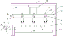
FIG. 1 is a front view of the present invention;
FIG. 2 is a structural diagram of the first transmission member and the second transmission member of the present invention;
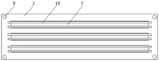
FIG. 3 is a schematic side sectional view of the barrel of the present invention;
the main element symbols are as follows:
the device comprises a working plate 1, a lifting plate 2, a hole pressing piece 3, a top plate 4, a first supporting leg 5, a hole groove 6, a sliding groove 7, a sliding block 8, a sliding hole 9, a second supporting leg 10, a hydraulic cylinder 11, a supporting column 12, a threaded column 13, an annular blade 14, an outer ring 15, a pressing spring 16, a pressing ring 17, a fixing strip 18, an anti-skidding pad 19, a threaded rod 20, a locking nut 21, a sundry material groove 22, a support 23, a fixing plate 24, an end shaft 25, a winding roller 26 and a handle 27.
Detailed Description
In order to make the present invention better understood by those skilled in the art, the technical solutions of the present invention are further described below with reference to the accompanying drawings and examples.
As shown in fig. 1-3, a non-woven fabric hole pressing device comprises a working plate 1, a lifting plate 2, a hole pressing member 3 and a top plate 4, wherein a first support leg 5 is fixedly connected to an angular point of the lower side of the working plate 1, a plurality of hole groove groups are arranged on the working plate 1 at equal intervals along the width direction of the working plate, and each hole groove group comprises a plurality of hole grooves 6 which are arranged at equal intervals along the length direction of the working plate 1; the lifting plate 2 is arranged right above the working plate 1, sliding holes 8 are formed in the angular points of the lifting plate 2, each sliding hole 8 is in sliding fit with a second supporting leg 10, sliding grooves 7 which correspond to the hole groove groups and penetrate through the upper surface and the lower surface of the lifting plate 2 are formed in the lifting plate 2, sliding blocks 8 are connected in the sliding grooves 7 in a sliding mode, and the hole pressing piece 3 is detachably connected to the lower side surface of each sliding block 8; the top plate 4 is fixed on the top ends of the four second supporting legs 10, a hydraulic cylinder 11 is fixedly connected to the lower side of the top plate 4, and the bottom end of a piston rod of the hydraulic cylinder 11 is fixedly connected to the lifting plate 2.
Specifically, hole pressing piece 3 includes pillar 12, the coaxial rigid coupling in top of pillar 12 has screw thread post 13, screw thread post 13 threaded connection is in the screw hole of 8 downside of slider, the coaxial rigid coupling in pillar 12 bottom has annular blade 14, annular blade 14's diameter is the same with 6 diameters in hole groove, pillar 12 bottom still rigid coupling has the outer loop 15 that is located the annular blade 14 outside, the bottom of outer loop 15 is higher than annular blade 14 bottom, the top in region is annular rigid coupling and has a plurality of pressure spring 16 between outer loop 15 and the annular blade 14, the common rigid coupling in bottom of pressure spring 16 has clamping ring 17.
Specifically, the upper end face of the sliding chute 7 is symmetrically and fixedly connected with a pair of fixing strips 18, the upper end faces of the fixing strips 18 are fixedly connected with anti-slip pads 19, the upper end faces of the sliding blocks 8 are fixedly connected with threaded rods 20, the diameter of each threaded rod 20 is equal to the distance between the two fixing strips 18, the top ends of the threaded rods 20 protrude out of the anti-slip pads 19, and locking nuts 21 are matched on the threaded rods 20.
Specifically, the end face of the lower port of the press ring 17 is provided with anti-skid grains.
Concretely, still include rolling drum 26, the symmetry rigid coupling has two supports 23 around the working plate 1 downside, and the one end rigid coupling that working plate 1 was kept away from to support 23 has fixed plate 24, and rolling drum 26 both ends are passed through the dead axle 25 and are rotated and connect between two fixed plates 24, and rolling drum 26 goes up the side and 1 side parallel and level of going up of working plate, and dead axle 25 of rear side runs through fixed plate 24 and rigid coupling has handle 27.
Specifically, a miscellaneous trough 22 is fixedly connected between the first support legs 5.
The working principle is as follows: one end of the non-woven fabric is wound on a winding roller after passing through a working plate, the hole pressing piece 3 is selectively connected to the lower side surface of the sliding block 8 according to requirements, the distance between the adjacent hole pressing pieces 3 is adjusted through the sliding block 8, each annular blade 14 is positioned right above the corresponding hole groove 6, the locking nut 21 on the threaded rod 20 is screwed, the locking nut 21 is tightly pressed on the anti-skid pad 19, the sliding block 8 is ensured not to easily move after being determined to be positioned, then the hydraulic cylinder 11 is started, the piston rod of the hydraulic cylinder 11 drives the lifting plate 2 and the hole pressing piece 3 to descend, in the descending process of the hole pressing piece 3, the pressing ring 17 firstly contacts the outer side surface at the upper end of the hole groove 6, along with the continuous descending of the hole pressing piece 3, the pressing ring 17 ascends relative to the outer ring 15 and compresses the pressing spring 16, the elastic force of the pressing spring 16 finally acts on the non-, the cut holes are flat and have no folds, and after the hydraulic cylinder 11 finishes one-time expansion, the winding roller 26 is rotated through the handle 27, and the subsequent parts of the non-woven fabric are pressed again.
It is right above the utility model provides a non-woven fabrics pressure hole device has carried out detailed introduction. The description of the specific embodiments is only intended to facilitate an understanding of the method of the invention and its core ideas. It should be noted that, for those skilled in the art, without departing from the principle of the present invention, the present invention can be further modified and modified, and such modifications and modifications also fall within the protection scope of the appended claims.
Claims (6)
1. A non-woven fabric hole pressing device comprises a working plate, a lifting plate, a hole pressing piece and a top plate, and is characterized in that,
the first supporting leg is fixedly connected to the angular point of the lower side of the working plate, a plurality of hole groove groups are arranged on the working plate at equal intervals along the width direction of the working plate, and each hole groove group comprises a plurality of hole grooves which are arranged at equal intervals along the length direction of the working plate;
the lifting plate is arranged right above the working plate, sliding holes are formed in the corners of the lifting plate, each sliding hole is matched with a second supporting leg in a sliding mode, sliding grooves which correspond to the hole groove groups and penetrate through the upper surface and the lower surface of the lifting plate are formed in the lifting plate, sliding blocks are connected in the sliding grooves in a sliding mode, and the hole pressing piece is detachably connected to the lower side surface of each sliding block;
the top plate is fixed on the top ends of the four second supporting legs, a hydraulic cylinder is fixedly connected to the lower side of the top plate, and the bottom end of a piston rod of the hydraulic cylinder is fixedly connected to the lifting plate.
2. The non-woven fabrics pressure hole device of claim 1, characterized in that, the pressure hole spare includes the pillar, the coaxial rigid coupling in top of pillar has the screw thread post, screw thread post threaded connection is in the screw hole of slider downside, and the coaxial rigid coupling in pillar bottom has annular blade, the diameter and the hole groove diameter of annular blade are the same, and the pillar bottom still rigid coupling has the outer loop that is located the annular blade outside, the bottom of outer loop is higher than the annular blade bottom, and regional top is annular rigid coupling and has a plurality of pressure spring between outer loop and the annular blade, the common rigid coupling in pressure spring's bottom has the clamping ring.
3. The non-woven fabric hole pressing device according to claim 1, wherein a pair of fixing strips is symmetrically and fixedly connected to the upper end face of the sliding groove, a non-slip mat is fixedly connected to the upper end face of each fixing strip, a threaded rod is fixedly connected to the upper end face of each sliding block, the diameter of each threaded rod is equal to the distance between the two fixing strips, the top end of each threaded rod protrudes out of the non-slip mat, and a locking nut is matched on each threaded rod.
4. The non-woven fabric hole pressing device according to claim 2, wherein the end face of the lower end opening of the pressing ring is provided with anti-skid grains.
5. The non-woven fabric hole pressing device according to claim 1, further comprising a winding roller, wherein two supports are symmetrically and fixedly connected to the front and the back of the lower side of the working plate, a fixing plate is fixedly connected to one end, away from the working plate, of each support, two ends of the winding roller are rotatably connected between the two fixing plates through end shafts, the upper side face of the winding roller is flush with the upper side face of the working plate, and the end shaft on the rear side penetrates through the fixing plates and is fixedly connected with a handle.
6. The non-woven fabric perforation device according to claim 1, wherein a miscellaneous material groove is fixedly connected between the first legs.
Priority Applications (1)
| Application Number | Priority Date | Filing Date | Title |
|---|---|---|---|
| CN201921369244.1U CN211030293U (en) | 2019-08-22 | 2019-08-22 | Non-woven fabrics pressure hole device |
Applications Claiming Priority (1)
| Application Number | Priority Date | Filing Date | Title |
|---|---|---|---|
| CN201921369244.1U CN211030293U (en) | 2019-08-22 | 2019-08-22 | Non-woven fabrics pressure hole device |
Publications (1)
| Publication Number | Publication Date |
|---|---|
| CN211030293U true CN211030293U (en) | 2020-07-17 |
Family
ID=71561965
Family Applications (1)
| Application Number | Title | Priority Date | Filing Date |
|---|---|---|---|
| CN201921369244.1U Expired - Fee Related CN211030293U (en) | 2019-08-22 | 2019-08-22 | Non-woven fabrics pressure hole device |
Country Status (1)
| Country | Link |
|---|---|
| CN (1) | CN211030293U (en) |
Cited By (1)
| Publication number | Priority date | Publication date | Assignee | Title |
|---|---|---|---|---|
| CN112809820A (en) * | 2021-01-21 | 2021-05-18 | 卢海勇 | Perforating device with collect waste material that corrugated paper processing used |
-
2019
- 2019-08-22 CN CN201921369244.1U patent/CN211030293U/en not_active Expired - Fee Related
Cited By (1)
| Publication number | Priority date | Publication date | Assignee | Title |
|---|---|---|---|---|
| CN112809820A (en) * | 2021-01-21 | 2021-05-18 | 卢海勇 | Perforating device with collect waste material that corrugated paper processing used |
Similar Documents
| Publication | Publication Date | Title |
|---|---|---|
| CN112160146B (en) | Cutting processing method of non-woven fabric clothing fabric | |
| CN104389107A (en) | Spunlaced hand rag for automobile industry and manufacturing method thereof | |
| CN101144226A (en) | Technique for preparing spunbonded water-jet bonding non-woven fabrics | |
| CN110983638B (en) | Production equipment and production method of elastic cotton cloth with four-side elasticity | |
| CN218372959U (en) | Device is tailor to non-woven fabrics with distance function | |
| CN203855781U (en) | Fiber net reinforcing device | |
| CN216765227U (en) | A many times compactor for geotechnique's cloth production | |
| CN202809186U (en) | High-temperature resistant carpet sleeve processing device for pleating machine | |
| CN207227696U (en) | A kind of novel energy-conserving carries effect needling device | |
| CN112877905A (en) | Manufacturing and forming process of spunlace non-woven fabric | |
| CN221441006U (en) | Composite needling machine | |
| CN211284926U (en) | Compression roller machine for producing home textile fabric | |
| CN214032987U (en) | Stretcher set for non-woven fabric production | |
| CN215976314U (en) | Needle plate clamping mechanism for single plate pre-needling reverse needling machine | |
| CN215625759U (en) | Collecting device capable of cutting non-woven fabric | |
| CN213267165U (en) | Composite embossed non-woven fabric processing device | |
| CN212608423U (en) | Winding device for spunlace non-woven fabric production line | |
| CN203699499U (en) | Feeding frame | |
| CN210454879U (en) | Weaving transport vechicle | |
| CN103771170A (en) | Feeding rack | |
| CN210711995U (en) | Single-shaft double-connecting-rod needling machine | |
| CN220639161U (en) | Water-guiding geotextile | |
| CN211733322U (en) | Coiling mechanism for cloth machine of compound cloth processing of polymer | |
| CN202410378U (en) | Polytetrafluoroethylene needling filtering material | |
| CN207003115U (en) | A kind of silk cutter device |
Legal Events
| Date | Code | Title | Description |
|---|---|---|---|
| GR01 | Patent grant | ||
| GR01 | Patent grant | ||
| CF01 | Termination of patent right due to non-payment of annual fee |
Granted publication date: 20200717 |
|
| CF01 | Termination of patent right due to non-payment of annual fee |