CN211027510U - Die steel hot rolling device with preheating mechanism - Google Patents
Die steel hot rolling device with preheating mechanism Download PDFInfo
- Publication number
- CN211027510U CN211027510U CN201921432604.8U CN201921432604U CN211027510U CN 211027510 U CN211027510 U CN 211027510U CN 201921432604 U CN201921432604 U CN 201921432604U CN 211027510 U CN211027510 U CN 211027510U
- Authority
- CN
- China
- Prior art keywords
- sides
- sliding
- driving motor
- base
- fixedly connected
- Prior art date
- Legal status (The legal status is an assumption and is not a legal conclusion. Google has not performed a legal analysis and makes no representation as to the accuracy of the status listed.)
- Expired - Fee Related
Links
- 229910000831 Steel Inorganic materials 0.000 title claims abstract description 46
- 239000010959 steel Substances 0.000 title claims abstract description 46
- 230000007246 mechanism Effects 0.000 title claims abstract description 16
- 238000005098 hot rolling Methods 0.000 title claims abstract description 13
- 239000007921 spray Substances 0.000 claims description 24
- 238000005096 rolling process Methods 0.000 claims description 21
- 238000000034 method Methods 0.000 abstract description 2
- 230000005012 migration Effects 0.000 abstract description 2
- 238000013508 migration Methods 0.000 abstract description 2
- 244000309464 bull Species 0.000 description 5
- 238000004519 manufacturing process Methods 0.000 description 3
- 238000000465 moulding Methods 0.000 description 2
- 230000004075 alteration Effects 0.000 description 1
- 230000009286 beneficial effect Effects 0.000 description 1
- 238000010586 diagram Methods 0.000 description 1
- 238000004512 die casting Methods 0.000 description 1
- 230000000694 effects Effects 0.000 description 1
- 238000005516 engineering process Methods 0.000 description 1
- 238000005242 forging Methods 0.000 description 1
- 230000003993 interaction Effects 0.000 description 1
- 238000012986 modification Methods 0.000 description 1
- 230000004048 modification Effects 0.000 description 1
- 238000007493 shaping process Methods 0.000 description 1
- 238000006467 substitution reaction Methods 0.000 description 1
Images
Landscapes
- Press Drives And Press Lines (AREA)
Abstract
The utility model discloses a mould steel hot rolling device with preheat mechanism, including the base, two first spouts have all been seted up to the both sides on base top, the both sides of four first spout inner walls respectively with the both sides sliding connection of four first sliders, the top of four first sliders respectively with the both sides fixed connection of two backup pad bottoms, the middle part of two backup pad one sides respectively with the one end threaded connection of two lead screws, the utility model relates to a mould steel hot rolling device with preheat mechanism, through setting up the lead screw, first driving motor drives the lead screw and rotates, the lead screw drives the backup pad through first slider horizontal migration, and the backup pad drives edger horizontal motion, can adjust the opening distance between the edger, makes the edger can carry out the roughing to the mould steel of different volumes, and the effective of the roughing process of being convenient for goes on.
Description
Technical Field
The utility model relates to a mould steel hot rolling, in particular to mould steel hot rolling device with preheat mechanism belongs to mould steel technical field.
Background
The die steel is used for manufacturing dies such as cold stamping dies, hot forging dies, die-casting dies and the like, and the dies are main processing tools for manufacturing parts in industrial departments such as mechanical manufacturing, radio instruments, motors, electric appliances and the like.
1. In the prior art, when die steel is subjected to hot rolling, the die steel needs to be subjected to rough rolling, the opening distance between the vertical rolls is mostly fixed during rough rolling, and the rough rolling cannot be fully performed due to the fact that the opening distance cannot be adjusted according to die steel with different volumes.
2. In the prior art, the rough rolling process of the die steel is mostly carried out once through a conveying device, and the rough rolling of the die steel can not be carried out for many times, so that the shape of the obtained die steel is incomplete, and the subsequent processing procedure is influenced.
3. Among the prior art, when carrying out rough rolling to the mould steel, directly go on usually, do not preheat the mould steel, reduce the shaping effect of mould steel, make the mould steel can not fully moulding.
SUMMERY OF THE UTILITY MODEL
An object of the utility model is to provide a mould steel hot rolling device with preheat mechanism to the problem that the opening distance that provides can not adjust and can not carry out the rough rolling many times in solving above-mentioned background art.
In order to achieve the above object, the utility model provides a following technical scheme: a die steel hot rolling device with a preheating mechanism comprises a base, wherein two sides of the top end of the base are respectively provided with two first sliding grooves, two sides of the inner wall of each first sliding groove are respectively connected with two sides of four first sliding blocks in a sliding manner, the top ends of the four first sliding blocks are respectively fixedly connected with two sides of the bottom ends of two supporting plates, the middle part of one side of each supporting plate is respectively in threaded connection with one ends of two lead screws, the other ends of the two lead screws are respectively fixedly connected with output shafts of two first driving motors, the two first driving motors are respectively fixedly arranged at the top ends of two motor bases, the two motor bases are respectively fixedly arranged at two sides of the top end of the base, the top ends of the two supporting plates are respectively fixedly connected with one side of the bottom ends of two top plates, the middle parts of the top ends of the two top plates are respectively and fixedly provided with second driving motors, the output shafts of the two second driving, the other ends of the two rotating shafts are respectively fixedly connected with the middle parts of the top ends of the two vertical rolls.
As a preferred technical scheme of the utility model, the both sides on base top are all fixed and are equipped with two first bracing pieces, four the top of first bracing piece one side respectively with the both sides fixed connection of two first dead levers, two the second spout has all been seted up on the top of first dead lever.
As a preferred technical scheme of the utility model, two the both sides of second spout inner wall respectively with the both sides sliding connection of four first slide bars, four the top of first slide bar one side respectively with the one end fixed connection of four second dead levers, four the other end of second dead lever respectively with the top fixed connection of two backup pad both sides.
As a preferred technical scheme of the utility model, the both sides on base top are all fixed and are equipped with two second bracing pieces, four the top of second bracing piece respectively with the both sides fixed connection of two second slide bar bottoms, two the both sides of second slide bar respectively with the both sides sliding connection of two third spout inner walls, and two third spouts set up respectively in the both sides of movable plate bottom.
As a preferred technical scheme of the utility model, the fixed third driving motor that is equipped with in middle part on base top, the output shaft of third driving motor and the middle part fixed connection of carousel bottom, the fixed bull stick that is equipped with in one side of carousel, the fourth spout has been seted up at the middle part on bull stick top, the both sides of fourth spout inner wall respectively with the both sides sliding connection of second slider, the middle part on second slider top is articulated with one side of connecting rod bottom, the opposite side on connecting rod bottom is articulated with one side on carousel top, the middle part of second slider one side and the bottom fixed connection of third slide bar one side, the top of third slide bar both sides and the both sides sliding connection of fifth spout inner wall, and the one side at the movable plate bottom is seted up to the fifth spout.
As a preferred technical scheme of the utility model, the fixed servo motor that is equipped with in one side on base top, servo motor's output shaft and one side fixed connection of semi-circular gear bottom, semi-circular gear is connected with the circular gear meshing, and the circular gear cover is established at the middle part of flame spray gun outer wall, the bottom and the circular slot of flame spray gun rotate to be connected, and the circular slot is seted up at the middle part on round bar top, the fixed one side that sets up on the base top of round bar, the model of flame spray gun is 516C.
As an optimal technical scheme of the utility model, the fixed flush mounting plate that is equipped with in one side of base, flush mounting plate's fixed first driving motor switch, second driving motor switch third driving motor switch, servo motor switch and the flame spray gun switch of being equipped with respectively in surface, first driving motor, second driving motor, third driving motor, servo motor and flame spray gun are respectively through corresponding first driving motor switch, second driving motor switch, third driving motor switch, servo motor switch and flame spray gun switch and external power supply electric connection.
Compared with the prior art, the beneficial effects of the utility model are that:
1. the utility model discloses set up the lead screw, first driving motor drives the lead screw and rotates, and the lead screw drives the backup pad and passes through first slider horizontal migration, and the backup pad drives edger roll horizontal motion, can adjust the opening distance between the edger roll, makes the edger roll carry out rough rolling to the mould steel of different volumes, and the effective of the rough rolling process of being convenient for goes on.
2. The utility model discloses set up the carousel, third driving motor drives the carousel and rotates, and the carousel drives the bull stick and rotates to drive the second slider and remove in the fourth spout, make the fourth slider be circular motion, thereby drive the third slide bar and be circular motion, the third slide bar can drive the movable plate and be horizontal reciprocating motion, makes the mould steel on the movable plate can obtain rough rolling many times, obtains comparatively complete mould steel.
3. The utility model discloses set up the semicircle gear, servo motor drives the semicircle gear revolve, and the semicircle gear drives the circle gear revolve to drive flame spray gun and rotate, make flame spray gun preheat each position of mould steel, make the mould steel soften, improved the plasticity of mould steel, make the mould steel fully moulding.
Drawings
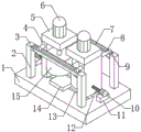
Fig. 1 is a schematic structural view of the present invention;
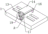
fig. 2 is a schematic structural view of the moving plate of the present invention;
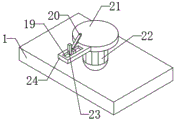
FIG. 3 is a schematic view of the reciprocating structure of the present invention;
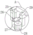
fig. 4 is a schematic diagram of the local enlarged structure at a.
In the figure: 1. a base; 2. a first support bar; 3. a first fixing lever; 4. a support plate; 5. a top plate; 6. a second drive motor; 7. a second chute; 8. a second fixing bar; 9. a first slide bar; 10. a first drive motor; 11. a motor base; 12. a lead screw; 13. a first chute; 14. moving the plate; 15. vertical rolls; 16. a second support bar; 17. a third chute; 18. a second slide bar; 19. a fourth chute; 20. a connecting rod; 21. a turntable; 22. a third drive motor; 23. a third slide bar; 24. a rotating rod; 25. a flame spray gun; 26. a circular gear; 27. a round bar; 28. a servo motor; 29. a semi-circular gear.
Detailed Description
The technology in the embodiment of the present invention will be described below with reference to the accompanying drawings in the embodiment of the present invention
The embodiments are described in detail, clearly, and not in their entirety, it is to be understood that the embodiments described are only some of the embodiments of the present invention and are not to be taken as a complete description. Based on the embodiments in the present invention, all other embodiments obtained by a person skilled in the art without creative work belong to the protection scope of the present invention.
Referring to fig. 1-3, the present invention provides a hot rolling device for mold steel with a preheating mechanism, comprising:
according to the figures 1 and 4, the device comprises a base 1, two first sliding grooves 13 are respectively arranged on two sides of the top end of the base 1, two sides of the inner wall of each first sliding groove 13 are respectively connected with two sides of each first sliding block in a sliding manner, the top ends of the four first sliding blocks are respectively fixedly connected with two sides of the bottom end of each support plate 4, the first sliding blocks slide to drive the support plates 4 to slide, so as to drive the vertical rolls 15 to slide, the distance between the two vertical rolls 15 can be changed, namely the opening distance of rough rolling can be adjusted, the middle parts of one sides of the two support plates 4 are respectively in threaded connection with one ends of two lead screws 12, the other ends of the two lead screws 12 are respectively fixedly connected with output shafts of two first driving motors 10, the two first driving motors 10 are respectively fixedly arranged on the top ends of two motor bases 11, the two motor bases 11 are respectively fixedly arranged on two sides of the top end, the surface of the switch panel is respectively fixedly provided with a first driving motor switch, a second driving motor switch, a third driving motor switch, a servo motor switch and a flame spray gun switch, the first driving motor 10, the second driving motor 6, the third driving motor 22, the servo motor 28 and the flame spray gun 25 are respectively electrically connected with an external power supply through the corresponding first driving motor switch, the second driving motor switch, the third driving motor switch, the servo motor switch and the flame spray gun switch to provide power for the first driving motor 10, so that the first driving motor 10 can normally rotate to drive the screw 12 to rotate, the screw 12 can drive the supporting plates 4 to horizontally move, the top ends of the two supporting plates 4 are respectively and fixedly connected with one side of the bottom ends of the two top plates 5, the middle parts of the top ends of the two top plates 5 are respectively and fixedly provided with the second driving motor 6, the output shafts of the two second driving motors 6 are respectively and fixedly connected with one end of the two rotating shafts, the other ends of the two rotating shafts are respectively fixedly connected with the middle parts of the top ends of the two vertical rolls 15, the second driving motor 6 works to drive the rotating shafts to rotate, the rotating shafts drive the vertical rolls 15 to rotate, the mold steel can be roughly rolled, a servo motor 28 is fixedly arranged on one side of the top end of the base 1, an output shaft of the servo motor 28 is fixedly connected with one side of the bottom end of a semicircular gear 29, the semicircular gear 29 is meshed with a circular gear 26, the circular gear 26 is sleeved on the middle part of the outer wall of the flame spray gun 25, the bottom end of the flame spray gun 25 is rotatably connected with the circular groove, the circular groove is formed in the middle part of the top end of a circular rod 27, the circular rod 27 is fixedly arranged on one side of the top end of the base 1, the model of the flame spray gun 25 is 516C, before rough rolling, a flame spray gun switch and a servo motor switch are opened, the servo motor 28 drives the, and preheating the surface of the die steel.
As shown in fig. 1, two first supporting rods 2 are fixedly arranged on two sides of the top end of a base 1, the tops of one side of each of the four first supporting rods 2 are fixedly connected with two sides of two first fixing rods 3 respectively, a second sliding groove 7 is formed in the top end of each of the two first fixing rods 3, two sides of the inner wall of each of the two second sliding grooves 7 are slidably connected with two sides of each of four first sliding rods 9 respectively, the tops of one sides of the four first sliding rods 9 are fixedly connected with one ends of the four second fixing rods 8 respectively, the other ends of the four second fixing rods 8 are fixedly connected with the tops of two sides of two supporting plates 4 respectively, when the supporting plates 4 move horizontally, the second fixing rods 8 are driven to move, the second fixing rods 8 drive the first sliding rods 9 to move, the first sliding rods 9 slide in the second sliding grooves 7, so that the supporting plates 4 are kept stable.
Referring to fig. 2 and 3, two second support rods 16 are fixedly disposed on two sides of the top end of the base 1, the top ends of the four second support rods 16 are respectively fixedly connected to two sides of the bottom ends of the two second slide rods 18, two sides of the two second slide rods 18 are respectively slidably connected to two sides of the inner walls of the two third slide grooves 17, the two third slide grooves 17 are respectively disposed on two sides of the bottom end of the moving plate 14, so that the moving plate 14 moves horizontally on the second slide rods 18, a third driving motor 22 is fixedly disposed in the middle of the top end of the base 1, the output shaft of the third driving motor 22 is fixedly connected to the middle of the bottom end of the rotary plate 21, a rotary rod 24 is fixedly disposed on one side of the rotary plate 21, a fourth slide groove 19 is disposed in the middle of the top end of the rotary rod 24, two sides of the inner wall of the fourth slide groove 19 are respectively slidably connected to two sides of the second slide block, the middle of the top end of, the middle part of one side of the second slide block is fixedly connected with the bottom of one side of the third slide bar 23, the tops of two sides of the third slide bar 23 are slidably connected with two sides of the inner wall of the fifth slide groove, the fifth slide groove is arranged at one side of the bottom end of the movable plate 14, the third driving motor 22 rotates to drive the rotary plate 21 to rotate, the rotary plate 21 drives the rotary rod 24 to rotate, the rotary rod 24 drives the second slide block to slide in the fourth slide groove 19, so that the second slide block performs circular motion, the second slide block drives the third slide bar 23 to perform circular motion, the movable plate 14 is driven to horizontally move, the die steel is placed at the top end of the movable plate 14, the die steel can be driven to perform reciprocating motion, and the vertical roller 15 can perform.
When the die steel hot rolling device is used, the utility model relates to a die steel hot rolling device with a preheating mechanism, firstly, a first driving motor switch is opened, a first driving motor 10 drives a screw rod 12 to rotate, the screw rod 12 drives a support plate 4 to move horizontally, the support plate 4 can drive a vertical roller 15 to move horizontally, thereby adjusting the opening distance during rough rolling, when the support plate 4 moves horizontally, a second fixing rod 8 is driven to move horizontally, the second fixing rod 8 drives a first slide rod 9 to move horizontally in a second chute 7, so that the support plate 4 keeps stable when moving without shaking, when the second driving motor switch is opened, a second driving motor 6 drives a rotating shaft to rotate, the rotating shaft drives the vertical roller 15 to rotate, the rough rolling is carried out on the die steel, the die steel is placed on a moving plate 14, the servo motor switch and a flame spray gun switch are opened, the servo motor 28 drives a semicircular gear 29 to rotate, the semicircular gear 29 drives a circular gear 26 to rotate, thereby drive flame spray gun 25 and rotate, heat the mould steel surface, open the third driving motor switch, third driving motor 22 drives carousel 21 and rotates, carousel 21 drives bull stick 24 and rotates, bull stick 24 drives the second slider and removes in fourth spout 19, makes the second slider do the circular motion, and the second slider drives third slide bar 23 and does the circular motion, and third slide bar 23 can drive movable plate 14 and do horizontal reciprocating motion, and vertical roll 15 can carry out the rough rolling many times to the mould steel on movable plate 14.
In the description of the present invention, it should be understood that the indicated orientation or positional relationship is based on the orientation or positional relationship shown in the drawings, and is only for convenience of description and simplification of description, and does not indicate or imply that the indicated device or element must have a particular orientation, be constructed and operated in a particular orientation, and thus should not be construed as limiting the present invention.
In the present invention, unless otherwise explicitly specified or limited, for example, it may be fixedly connected, detachably connected, or integrated; can be mechanically or electrically connected; they may be directly connected or indirectly connected through an intermediate medium, and may be connected through the inside of two elements or in an interaction relationship between two elements, unless otherwise specifically defined, and the specific meaning of the above terms in the present invention will be understood by those skilled in the art according to specific situations.
Although embodiments of the present invention have been shown and described, it will be appreciated by those skilled in the art that changes, modifications, substitutions and alterations can be made in these embodiments without departing from the principles and spirit of the invention, the scope of which is defined in the appended claims and their equivalents.
Claims (7)
1. A hot rolling device for die steel with a preheating mechanism comprises a base (1), and is characterized in that: two first sliding grooves (13) are respectively formed in two sides of the top end of the base (1), two sides of the inner wall of each first sliding groove (13) are respectively connected with two sides of four first sliding blocks in a sliding mode, the top ends of the four first sliding blocks are respectively fixedly connected with two sides of the bottom ends of two supporting plates (4), the middle portion of one side of each of the two supporting plates (4) is respectively connected with one end of each of two lead screws (12) in a threaded mode, the other ends of the two lead screws (12) are respectively fixedly connected with output shafts of two first driving motors (10), the two first driving motors (10) are respectively fixedly arranged at the top ends of two motor bases (11), the two motor bases (11) are respectively fixedly arranged on two sides of the top end of the base (1), the top ends of the two supporting plates (4) are respectively fixedly connected with one side of the bottom ends of the two top plates (5), and second driving motors (6) are respectively fixedly arranged in the middle portions of, the output shafts of the two second driving motors (6) are fixedly connected with one ends of the two rotating shafts respectively, and the other ends of the two rotating shafts are fixedly connected with the middle parts of the top ends of the two vertical rolls (15) respectively.
2. The hot mold steel rolling apparatus with a preheating mechanism according to claim 1, characterized in that: the two sides of the top end of the base (1) are fixedly provided with two first supporting rods (2), four the top of one side of each first supporting rod (2) is fixedly connected with the two sides of the two first fixing rods (3) respectively, and the top ends of the first fixing rods (3) are provided with second sliding grooves (7).
3. The hot mold steel rolling apparatus with a preheating mechanism according to claim 2, characterized in that: two the both sides of second spout (7) inner wall respectively with the both sides sliding connection of four first slide bars (9), four the top of first slide bar (9) one side respectively with the one end fixed connection of four second dead lever (8), four the other end of second dead lever (8) respectively with the top fixed connection of two backup pad (4) both sides.
4. The hot mold steel rolling apparatus with a preheating mechanism according to claim 1, characterized in that: the both sides on base (1) top all are fixed and are equipped with two second bracing pieces (16), four the top of second bracing piece (16) respectively with the both sides fixed connection of two second slide bar (18) bottoms, two the both sides of second slide bar (18) respectively with the both sides sliding connection of two third spout (17) inner walls, and two third spout (17) set up respectively in the both sides of movable plate (14) bottom.
5. The hot mold steel rolling apparatus with a preheating mechanism according to claim 1, characterized in that: a third driving motor (22) is fixedly arranged in the middle of the top end of the base (1), an output shaft of the third driving motor (22) is fixedly connected with the middle of the bottom end of the rotary table (21), a rotating rod (24) is fixedly arranged on one side of the rotating disk (21), a fourth sliding groove (19) is arranged in the middle of the top end of the rotating rod (24), two sides of the inner wall of the fourth sliding chute (19) are respectively connected with two sides of the second sliding block in a sliding way, the middle part of the top end of the second sliding block is hinged with one side of the bottom end of the connecting rod (20), the other side of the bottom end of the connecting rod (20) is hinged with one side of the top end of the rotating disc (21), the middle part of one side of the second sliding block is fixedly connected with the bottom of one side of the third sliding rod (23), the tops of the two sides of the third sliding rod (23) are in sliding connection with the two sides of the inner wall of the fifth sliding groove, and the fifth sliding groove is formed in one side of the bottom end of the moving plate (14).
6. The hot mold steel rolling apparatus with a preheating mechanism according to claim 1, characterized in that: the fixed servo motor (28) that is equipped with in one side on base (1) top, one side fixed connection in output shaft and semicircle gear (29) bottom of servo motor (28), semicircle gear (29) are connected with round gear (26) meshing, and round gear (26) cover establishes the middle part at flame spray gun (25) outer wall, the bottom and the circular slot of flame spray gun (25) rotate to be connected, and the circular slot is seted up at the middle part on round bar (27) top, round bar (27) are fixed to be set up in one side on base (1) top, the model of flame spray gun (25) is 516C.
7. The hot mold steel rolling apparatus with a preheating mechanism according to claim 1, characterized in that: the fixed flush mounting plate that is equipped with in one side of base (1), flush mounting plate's surface is fixed respectively and is equipped with first driving motor switch, second driving motor switch, third driving motor switch, fourth driving switch and flame spray gun switch, first driving motor (10), second driving motor (6), third driving motor (22), servo motor (28) and flame spray gun (25) are respectively through corresponding first driving motor switch, second driving motor switch, third driving motor switch, servo motor switch and flame spray gun switch and external power supply electric connection.
Priority Applications (1)
| Application Number | Priority Date | Filing Date | Title |
|---|---|---|---|
| CN201921432604.8U CN211027510U (en) | 2019-08-30 | 2019-08-30 | Die steel hot rolling device with preheating mechanism |
Applications Claiming Priority (1)
| Application Number | Priority Date | Filing Date | Title |
|---|---|---|---|
| CN201921432604.8U CN211027510U (en) | 2019-08-30 | 2019-08-30 | Die steel hot rolling device with preheating mechanism |
Publications (1)
| Publication Number | Publication Date |
|---|---|
| CN211027510U true CN211027510U (en) | 2020-07-17 |
Family
ID=71530819
Family Applications (1)
| Application Number | Title | Priority Date | Filing Date |
|---|---|---|---|
| CN201921432604.8U Expired - Fee Related CN211027510U (en) | 2019-08-30 | 2019-08-30 | Die steel hot rolling device with preheating mechanism |
Country Status (1)
| Country | Link |
|---|---|
| CN (1) | CN211027510U (en) |
Cited By (1)
| Publication number | Priority date | Publication date | Assignee | Title |
|---|---|---|---|---|
| CN112934954A (en) * | 2021-01-25 | 2021-06-11 | 句容建荣汽配有限公司 | Can reduce workman intensity of labour's flat line one shot forming device of no bone |
-
2019
- 2019-08-30 CN CN201921432604.8U patent/CN211027510U/en not_active Expired - Fee Related
Cited By (1)
| Publication number | Priority date | Publication date | Assignee | Title |
|---|---|---|---|---|
| CN112934954A (en) * | 2021-01-25 | 2021-06-11 | 句容建荣汽配有限公司 | Can reduce workman intensity of labour's flat line one shot forming device of no bone |
Similar Documents
| Publication | Publication Date | Title |
|---|---|---|
| CN118372155A (en) | A polishing machine for mold manufacturing | |
| CN216881782U (en) | Die hole groove machining device | |
| CN211220090U (en) | Mould grinding device | |
| CN220999751U (en) | Annealing furnace for bearing production | |
| CN210256881U (en) | Automobile parts mould pitch positioner | |
| CN117111655B (en) | Temperature control system for mold production | |
| CN215745743U (en) | Positioning device for hot stamping machine | |
| CN221110913U (en) | Feeding device for processing die steel materials | |
| CN209920613U (en) | Mechanical material preparation mould | |
| CN112705710A (en) | Shaping mechanism of powder metallurgy product | |
| CN220682036U (en) | Mobile phone rear cover texture processing die | |
| CN215700535U (en) | Machining mold surface processing device | |
| CN220887617U (en) | Rotary heat treatment device for die steel surface | |
| CN213004424U (en) | Mechanical die surfacing processing device | |
| CN220261392U (en) | Curing device for inorganic artificial stone | |
| CN223313638U (en) | A ductile iron pipe mold repairing and grinding machine with telescopic function | |
| CN222021310U (en) | Composite modified high-performance natural rubber processing equipment | |
| CN212494743U (en) | Knitting needle track die of single-side circular knitting machine for quantum energy wave heating knitted underwear | |
| CN215103416U (en) | Vertical extrusion quenching furnace for die steel production | |
| CN224238023U (en) | Integrated kitchen casing blanking mould | |
| CN218660055U (en) | Die device with turnover mechanism | |
| CN218798953U (en) | Quick die changing equipment of automatic molding machine | |
| CN218803608U (en) | Mold Support Frame for Injection Molding | |
| CN218518346U (en) | Casting primary finished product grinding device | |
| CN219581514U (en) | Furniture mould apparatus for producing convenient to dismouting |
Legal Events
| Date | Code | Title | Description |
|---|---|---|---|
| GR01 | Patent grant | ||
| GR01 | Patent grant | ||
| CF01 | Termination of patent right due to non-payment of annual fee | ||
| CF01 | Termination of patent right due to non-payment of annual fee |
Granted publication date: 20200717 Termination date: 20210830 |