CN211015296U - A computer host dust cleaning device - Google Patents
A computer host dust cleaning device Download PDFInfo
- Publication number
- CN211015296U CN211015296U CN202020052747.2U CN202020052747U CN211015296U CN 211015296 U CN211015296 U CN 211015296U CN 202020052747 U CN202020052747 U CN 202020052747U CN 211015296 U CN211015296 U CN 211015296U
- Authority
- CN
- China
- Prior art keywords
- fixed
- wall
- suction
- box
- dust
- Prior art date
- Legal status (The legal status is an assumption and is not a legal conclusion. Google has not performed a legal analysis and makes no representation as to the accuracy of the status listed.)
- Expired - Fee Related
Links
Images


Landscapes
- Cleaning In General (AREA)
Abstract
本实用新型公开了一种计算机主机灰尘清理装置,包括清理箱,所述清理箱铰接有箱门,且清理箱开设有通口,所述清理箱底部内壁中部固定有电动滑轨,且电动滑轨的滑动件顶部外壁固定有放置板,所述放置板顶部外一侧固定有固定罩,所述固定罩内壁中部固定有隔板,所述隔板顶部外壁固定有微型气泵,且微型气泵的出气端固定有出气管,所述出气管固定连接有吹气部件。本实用新型将主机放在放置板上,主机抵住固定罩,微信气泵运行配合吹气部件并通过主机后盖上的孔洞向主机内部吹气,将主机内部灰尘吹起,然后微型吸气泵运行配合吸气部件将主机内部漂浮的灰尘吸进吸气箱内,一吹一吸可将主机内部灰尘清理干净。

The utility model discloses a computer host dust cleaning device, comprising a cleaning box, a box door is hingedly connected with the cleaning box, and a through opening is opened in the cleaning box, an electric sliding rail is fixed in the middle of the inner wall of the bottom of the cleaning box, and the electric sliding A placing plate is fixed on the outer wall of the top of the sliding part of the rail, a fixing cover is fixed on the outer side of the top of the placing plate, a partition is fixed in the middle of the inner wall of the fixing cover, and a micro air pump is fixed on the outer wall of the top of the partition, and the micro air pump is fixed. The air outlet end is fixed with an air outlet pipe, and the air outlet pipe is fixedly connected with an air blowing component. In the utility model, the host is placed on the placing plate, the host is against the fixed cover, the micro-channel air pump operates and cooperates with the blowing parts and blows air into the host through the holes on the back cover of the host to blow up the dust inside the host, and then the micro air suction pump The operation cooperates with the suction part to suck the floating dust inside the host into the suction box, and the dust inside the host can be cleaned by blowing and sucking.
Description
技术领域technical field
本实用新型涉及计算机技术领域,尤其涉及一种计算机主机灰尘清理装置。The utility model relates to the technical field of computers, in particular to a computer host dust cleaning device.
背景技术Background technique
电子计算机通称电脑,是现代一种用于高速计算的电子计算机器,可以进行数值计算、逻辑计算,具有存储记忆功能,能够按照程序运行,自动、高速处理海量数据,因有些组成工厂环境较差,所以计算机组装好后,一般会通过人工用气枪将机箱内的灰尘进行清除,需要一直用手拿着气枪,长时间的拿着气枪手易酸痛,且只是简单的清理主机表面灰尘,无法对主机内部灰尘进行清理。Electronic computer, commonly known as computer, is a modern electronic computing machine used for high-speed calculation. It can perform numerical calculation and logical calculation, has storage and memory function, can run according to the program, and process massive data automatically and at high speed. Due to the poor environment of some factories , so after the computer is assembled, the dust in the chassis is generally removed by manual air gun. Clean the dust inside the host.
实用新型内容Utility model content
本实用新型的目的是为了解决现有技术中存在的缺点,而提出的一种计算机主机灰尘清理装置。The purpose of the utility model is to propose a computer host dust cleaning device in order to solve the shortcomings existing in the prior art.
为了实现上述目的,本实用新型采用了如下技术方案:In order to achieve the above-mentioned purpose, the utility model adopts the following technical solutions:
一种计算机主机灰尘清理装置,包括清理箱,所述清理箱铰接有箱门,且清理箱开设有通口,所述清理箱底部内壁中部固定有电动滑轨,且电动滑轨的滑动件顶部外壁固定有放置板,所述放置板顶部外一侧固定有固定罩,所述固定罩内壁中部固定有隔板,所述隔板顶部外壁固定有微型气泵,且微型气泵的出气端固定有出气管,所述出气管固定连接有吹气部件,所述固定罩底部内壁固定有微型吸气泵,且微型吸气泵吸气端固定有吸气管,所述吸气管螺接有吸气部件,所述放置板顶部外壁放置有主机,且主机背面与固定罩相接触,所述清理箱内部中部固定有C字状集气管,且C字状集气管顶部外壁开设有两个对称分布的第一出气口,两个所述第一出气口的内壁均通过管道连接有第一排气管,且C字状集气管两侧外壁均开设有两个对称分布的第二出气口,两个所述第二出气口的内壁均通过管道连接有第二排气管,所述主机和放置板均位于C字状集气管之间,且第一排气管和第二排气管靠近主机的一侧外壁均开设有等距离分布的排气孔,所述清理箱一边外壁中部固定有气泵,且气泵的出气端套接有输气管,所述输气管与C字状集气管相连通,所述清理箱顶部外壁固定有吸尘机构。A computer host dust cleaning device, comprising a cleaning box, the cleaning box is hinged with a box door, and the cleaning box is provided with a through opening, an electric sliding rail is fixed in the middle of the inner wall of the bottom of the cleaning box, and the top of the sliding part of the electric sliding rail is fixed. A placing plate is fixed on the outer wall, a fixed cover is fixed on the outer side of the top of the placing plate, a partition is fixed in the middle of the inner wall of the fixed cover, a micro air pump is fixed on the outer wall of the top of the partition, and an outlet of the micro air pump is fixed at the gas outlet end. The air pipe, the air outlet pipe is fixedly connected with an air blowing part, the inner wall of the bottom of the fixed cover is fixed with a micro suction pump, and the suction end of the micro suction pump is fixed with a suction pipe, and the suction pipe is screwed with a suction pipe Parts, the top outer wall of the placement plate is placed with the main machine, and the back of the main machine is in contact with the fixed cover, the middle part of the cleaning box is fixed with a C-shaped gas collecting pipe, and the outer wall of the top of the C-shaped gas collecting pipe is provided with two symmetrically distributed The first air outlet, the inner walls of the two first air outlets are connected with a first exhaust pipe through pipes, and the outer walls on both sides of the C-shaped air collecting pipe are provided with two symmetrically distributed second air outlets, two The inner wall of the second air outlet is connected with a second exhaust pipe through a pipeline, the main engine and the placing plate are located between the C-shaped air collecting pipes, and the first exhaust pipe and the second exhaust pipe are close to the main engine. The outer wall of one side is provided with exhaust holes distributed at equal distances, an air pump is fixed in the middle of the outer wall of one side of the cleaning box, and the air outlet end of the air pump is sleeved with an air delivery pipe, and the air delivery pipe is communicated with the C-shaped gas collecting pipe, so A dust suction mechanism is fixed on the outer wall of the top of the cleaning box.
优选的,所述吹气部件包括出气箱,且出气箱固定于隔板的顶部外壁上,所述出气箱靠近主机的一侧外壁开设有等距离分布的出气孔,且出气孔的内壁固定有喷嘴,所述出气箱靠近出气管的一侧外壁开设有进气口与出气管固定连接。Preferably, the air blowing component includes an air outlet box, and the air outlet box is fixed on the top outer wall of the partition, the outer wall of one side of the air outlet box close to the main machine is provided with air outlet holes distributed at equal distances, and the inner wall of the air outlet holes is fixed with A nozzle, the outer wall of one side of the air outlet box close to the air outlet pipe is provided with an air inlet and is fixedly connected with the air outlet pipe.
优选的,所述吸气部件包括吸气箱和吸气罩,且吸气箱固定于固定罩的底部内壁上,所述吸气箱靠近主机的一侧外壁开设有吸气口,且吸气罩固定于吸气口的内壁上,所述吸气箱一边外壁开设有开口,且开口的内壁卡接有密封板,所述密封板靠近开口的一侧外壁固定过滤网,且密封板通过螺栓与吸气箱固定连接,所述吸气箱靠近吸气管的一侧外壁设置有连接管,且连接管与吸气管相螺接。Preferably, the suction component includes a suction box and a suction hood, and the suction box is fixed on the bottom inner wall of the fixed cover, and an outer wall of one side of the suction box close to the main machine is provided with a suction port, and the suction box is The cover is fixed on the inner wall of the suction port, the outer wall of one side of the suction box is provided with an opening, and the inner wall of the opening is clamped with a sealing plate, the outer wall of the sealing plate close to the opening is fixed with a filter screen, and the sealing plate is bolted through. It is fixedly connected with the suction box, the outer wall of one side of the suction box close to the suction pipe is provided with a connecting pipe, and the connecting pipe is screwed with the suction pipe.
优选的,所述吸尘机构包括吸尘箱、吸尘管和吸尘罩,且吸尘箱固定于清理箱顶部外壁上,所述吸尘箱靠近箱门的一侧外壁开设有吸尘口,且吸尘管固定于吸尘口的内壁上,所述吸尘罩固定于清理箱靠近通口的顶部内壁上,且吸尘管与吸尘罩相连通,所述吸尘箱远离吸尘管的底部内壁一侧固定有吸尘泵,且吸尘箱靠近吸尘泵的底部内壁固定有防尘网罩,所述吸尘泵位于防尘网罩内部,且吸尘泵的排气管延伸至吸尘箱外。Preferably, the vacuuming mechanism includes a vacuuming box, a vacuuming pipe and a vacuuming cover, and the vacuuming box is fixed on the outer wall of the top of the cleaning box, and a vacuuming port is opened on the outer wall of one side of the vacuuming box close to the box door. , and the suction pipe is fixed on the inner wall of the suction port, the suction hood is fixed on the top inner wall of the cleaning box close to the opening, and the suction pipe is connected with the suction hood, and the suction box is far away from the suction box. A suction pump is fixed on one side of the inner wall of the bottom of the pipe, and a dust-proof net cover is fixed on the bottom inner wall of the suction box close to the suction pump. The suction pump is located inside the dust-proof net cover, and the exhaust pipe of the suction pump is Extends out of the vacuum box.
优选的,所述放置板远离固定罩的底部外壁固定有两个对称分布的支撑滚轮,且电动滑轨位于支撑滚轮之间。Preferably, two symmetrically distributed support rollers are fixed to the bottom outer wall of the placing plate away from the fixing cover, and the electric sliding rail is located between the support rollers.
优选的,所述吸尘箱外壁开设有清理口,且吸尘箱铰接有与清理口相适配的盖板。Preferably, the outer wall of the vacuum box is provided with a cleaning port, and the vacuum box is hinged with a cover plate adapted to the cleaning port.
优选的,所述电动滑轨、微型气泵、微型吸气泵、气泵和吸尘泵均通过导线连接有开关,且开关通过导线连接有PLC控制器。Preferably, the electric slide rail, the micro air pump, the micro air suction pump, the air pump and the dust suction pump are all connected with switches through wires, and the switches are connected with a PLC controller through wires.
本实用新型的有益效果为:The beneficial effects of the present utility model are:
1、本计算机主机灰尘清理装置,将主机放在放置板上,主机抵住固定罩,微信气泵运行配合吹气部件并通过主机后盖上的孔洞向主机内部吹气,将主机内部灰尘吹起,然后微型吸气泵运行配合吸气部件将主机内部漂浮的灰尘吸进吸气箱内,一吹一吸可将主机内部灰尘清理干净。1. This computer host dust cleaning device, put the host on the placement board, the host is against the fixed cover, the WeChat air pump runs with the blowing parts and blows air into the host through the holes on the back cover of the host to blow up the dust inside the host , and then the micro-aspirator works with the suction components to suck the floating dust inside the host into the suction box, and the dust inside the host can be cleaned up by blowing and sucking.
2、本计算机主机灰尘清理装置,C字状集气管靠近主机的三边外壁分别设置了一个第一排气管和两个第二排气管,可通过气泵在安置板配合电动滑轨在C字状集气管之间来回运行时,将主机表面灰尘吹气,且吹走的灰尘可被吸尘部件吸收,结合一吸一吹可实现全面清理灰尘的效果。2. The computer host dust cleaning device, the C-shaped gas collecting pipe is close to the three-sided outer wall of the host, and a first exhaust pipe and two second exhaust pipes are respectively set. When the character-shaped air collecting pipes are running back and forth, the dust on the surface of the main machine is blown, and the dust blown away can be absorbed by the dust-absorbing parts. Combined with one suction and one blow, the effect of comprehensive cleaning of dust can be achieved.
附图说明Description of drawings
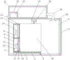
图1为本实用新型提出的一种计算机主机灰尘清理装置的竖截面结构示意图;Fig. 1 is the vertical sectional structure schematic diagram of a kind of computer host dust cleaning device proposed by the utility model;
图2为本实用新型提出的一种计算机主机灰尘清理装置的吸尘箱侧视竖截面结构示意图;Fig. 2 is a side view vertical cross-sectional structural schematic diagram of a dust collector of a computer host dust cleaning device proposed by the utility model;
图3为本实用新型提出的一种计算机主机灰尘清理装置的固定罩侧视结构示意图;3 is a schematic structural diagram of a side view of a fixed cover of a computer host dust cleaning device proposed by the utility model;
图4为本实用新型提出的一种计算机主机灰尘清理装置的主视结构示意图;4 is a schematic front view of the structure of a computer host dust cleaning device proposed by the utility model;
图5为本实用新型提出的一种计算机主机灰尘清理装置的C字状集气管侧视竖截面结构示意图。5 is a schematic side view of a vertical cross-sectional structure diagram of a C-shaped gas collecting pipe of a computer host dust cleaning device proposed by the utility model.
图中:1清理箱、2箱门、3通口、4电动滑轨、5放置板、6支撑滚轮、7固定罩、8隔板、9微型气泵、10出气管、11出气箱、12喷嘴、13微型吸气泵、14吸气管、15吸气箱、16吸气罩、17过滤网、18主机、19 C字状集气管、20第一排气管、21吸尘箱、22吸尘泵、23吸尘管、24吸尘罩、25防尘网罩、26密封板、27气泵、28输气管、29盖板、30第二排气管、31排气孔。In the picture: 1 cleaning box, 2 box doors, 3 ports, 4 electric slide rails, 5 placing plates, 6 supporting rollers, 7 fixing covers, 8 partitions, 9 micro air pumps, 10 air outlet pipes, 11 air outlet boxes, 12 nozzles , 13 micro suction pump, 14 suction pipe, 15 suction box, 16 suction hood, 17 filter screen, 18 main engine, 19 C-shaped gas collecting pipe, 20 first exhaust pipe, 21 suction box, 22 suction Dust pump, 23 dust pipe, 24 dust cover, 25 dust net cover, 26 sealing plate, 27 air pump, 28 air pipe, 29 cover plate, 30 second exhaust pipe, 31 exhaust hole.
具体实施方式Detailed ways
下面将结合本实用新型实施例中的附图,对本实用新型实施例中的技术方案进行清楚、完整地描述,显然,所描述的实施例仅仅是本实用新型一部分实施例,而不是全部的实施例。The technical solutions in the embodiments of the present utility model will be clearly and completely described below with reference to the accompanying drawings in the embodiments of the present utility model. Obviously, the described embodiments are only a part of the embodiments of the present utility model, rather than all the implementations. example.
参照图1-5,一种计算机主机灰尘清理装置,包括清理箱1,清理箱1铰接有箱门2,且清理箱1开设有通口3,清理箱1底部内壁中部固定有电动滑轨4,且电动滑轨4的滑动件顶部外壁固定有放置板5,放置板5顶部外一侧固定有固定罩7,固定罩7内壁中部固定有隔板8,隔板8顶部外壁固定有微型气泵9,且微型气泵9的出气端固定有出气管10,出气管10固定连接有吹气部件,固定罩7底部内壁固定有微型吸气泵13,且微型吸气泵13吸气端固定有吸气管14,吸气管14螺接有吸气部件,放置板5顶部外壁放置有主机18,且主机18背面与固定罩7相接触,清理箱1内部中部固定有C字状集气管19,且C字状集气管19顶部外壁开设有两个对称分布的第一出气口,两个第一出气口的内壁均通过管道连接有第一排气管20,且C字状集气管19两侧外壁均开设有两个对称分布的第二出气口,两个第二出气口的内壁均通过管道连接有第二排气管30,主机18和放置板5均位于C字状集气管19之间,且第一排气管20和第二排气管30靠近主机18的一侧外壁均开设有等距离分布的排气孔31,清理箱1一边外壁中部固定有气泵27,且气泵27的出气端套接有输气管28,输气管28与C字状集气管19相连通,清理箱1顶部外壁固定有吸尘机构,吹气部件包括出气箱11,且出气箱11固定于隔板8的顶部外壁上,出气箱11靠近主机18的一侧外壁开设有等距离分布的出气孔,且出气孔的内壁固定有喷嘴12,出气箱11靠近出气管10的一侧外壁开设有进气口与出气管10固定连接,吸气部件包括吸气箱15和吸气罩16,且吸气箱15固定于固定罩7的底部内壁上,吸气箱15靠近主机18的一侧外壁开设有吸气口,且吸气罩16固定于吸气口的内壁上,吸气箱15一边外壁开设有开口,且开口的内壁卡接有密封板26,密封板26靠近开口的一侧外壁固定过滤网17,且密封板26通过螺栓与吸气箱15固定连接,吸气箱15靠近吸气管14的一侧外壁设置有连接管,且连接管与吸气管14相螺接,吸尘机构包括吸尘箱21、吸尘管23和吸尘罩24,且吸尘箱21固定于清理箱1顶部外壁上,吸尘箱21靠近箱门2的一侧外壁开设有吸尘口,且吸尘管23固定于吸尘口的内壁上,吸尘罩24固定于清理箱1靠近通口3的顶部内壁上,且吸尘管23与吸尘罩24相连通,吸尘箱21远离吸尘管23的底部内壁一侧固定有吸尘泵22,且吸尘箱21靠近吸尘泵22的底部内壁固定有防尘网罩25,吸尘泵22位于防尘网罩25内部,且吸尘泵22的排气管延伸至吸尘箱21外,放置板5远离固定罩7的底部外壁固定有两个对称分布的支撑滚轮6,且电动滑轨4位于支撑滚轮6之间,吸尘箱21外壁开设有清理口,且吸尘箱21铰接有与清理口相适配的盖板29,电动滑轨4、微型气泵9、微型吸气泵13、气泵27和吸尘泵22均通过导线连接有开关,且开关通过导线连接有PLC控制器。1-5, a computer host dust cleaning device includes a
工作原理:使用时,打开箱门2将主机18后盖朝着固定罩7放置于放置板5上,然后推动主机18,使主机18的后盖贴住固定罩7,然后关闭箱门2,微型气泵9运行通过出气管10将吸入的空气排入出气箱11内并最终通过多个喷嘴12喷向主机后盖,喷出的空气会经过主机18后盖上的孔洞进入主机18内部,将主机18内部的灰尘吹起,然后微型吸气泵13运行通过吸气管14和吸气罩16将主机18内部的飘起的灰尘吸入吸气箱15内,吸入的灰尘会被过滤网17所拦截留在吸气箱15内部,一吹一吸可将主机18内部的灰尘清理掉,在对主机18内部灰尘清理的期间,电动滑轨4会带动安置板5上的主机18不断地C字形集气管19之间运行,与此同时,气泵27运行通过输气管28向C字状集气管19内输送空气并最终通过两个第二排气管30的排气孔31和第一排气管20上的排气孔31排出,即将不断的在C字形集气管19之间运行主机18表面灰尘吹起,这时,吸尘泵22运行通过吸尘管23和吸尘罩24将清理箱1内部飘起的灰尘吸入吸尘箱21内,一段时间后,即可完成对主机18的清理,打开箱门2拿出主机18即可,使用完毕后,打开盖板29对吸尘箱21内部灰尘进行清理,将吸气箱15取出并拧出螺栓,即可对密封板26上的过滤网17和吸气箱15内部灰尘进行清理。Working principle: When in use, open the
以上所述,仅为本实用新型较佳的具体实施方式,但本实用新型的保护范围并不局限于此,任何熟悉本技术领域的技术人员在本实用新型揭露的技术范围内,根据本实用新型的技术方案及其实用新型构思加以等同替换或改变,都应涵盖在本实用新型的保护范围之内。The above description is only a preferred embodiment of the present invention, but the protection scope of the present invention is not limited to this. Equivalent replacement or modification of the new technical solution and its utility model concept shall be included within the protection scope of the present utility model.
Claims (7)
Priority Applications (1)
| Application Number | Priority Date | Filing Date | Title |
|---|---|---|---|
| CN202020052747.2U CN211015296U (en) | 2020-01-10 | 2020-01-10 | A computer host dust cleaning device |
Applications Claiming Priority (1)
| Application Number | Priority Date | Filing Date | Title |
|---|---|---|---|
| CN202020052747.2U CN211015296U (en) | 2020-01-10 | 2020-01-10 | A computer host dust cleaning device |
Publications (1)
| Publication Number | Publication Date |
|---|---|
| CN211015296U true CN211015296U (en) | 2020-07-14 |
Family
ID=71476209
Family Applications (1)
| Application Number | Title | Priority Date | Filing Date |
|---|---|---|---|
| CN202020052747.2U Expired - Fee Related CN211015296U (en) | 2020-01-10 | 2020-01-10 | A computer host dust cleaning device |
Country Status (1)
| Country | Link |
|---|---|
| CN (1) | CN211015296U (en) |
Cited By (1)
| Publication number | Priority date | Publication date | Assignee | Title |
|---|---|---|---|---|
| CN113731951A (en) * | 2021-09-08 | 2021-12-03 | 博众精工科技股份有限公司 | Dust cleaning device |
-
2020
- 2020-01-10 CN CN202020052747.2U patent/CN211015296U/en not_active Expired - Fee Related
Cited By (1)
| Publication number | Priority date | Publication date | Assignee | Title |
|---|---|---|---|---|
| CN113731951A (en) * | 2021-09-08 | 2021-12-03 | 博众精工科技股份有限公司 | Dust cleaning device |
Similar Documents
| Publication | Publication Date | Title |
|---|---|---|
| CN113207267B (en) | A lift-type integrated computer server cabinet | |
| CN203725433U (en) | Blowing-suction cleaning device for glass production line | |
| CN209139347U (en) | One kind passing through formula ultrasonic cleaning, drying equipment | |
| CN107716186A (en) | A vertical spray booth system | |
| CN208495225U (en) | A kind of computer host dust-extraction unit | |
| CN211687359U (en) | Conveying device for cutting ultra-white toughened glass | |
| CN211073201U (en) | Dust collection box capable of removing chips quickly | |
| CN108406603A (en) | A kind of dust elimination noise abatement Sanding Room | |
| CN208180513U (en) | A kind of printing processing dust-extraction unit | |
| CN116117986B (en) | Dust removal equipment for a concrete block production line | |
| CN112024508A (en) | Dedusting and blowing equipment for drawer cabinets | |
| CN219276478U (en) | Material sucking device with dust removing mechanism | |
| CN216776867U (en) | Vacuum cleaner | |
| CN211639208U (en) | Ash handling equipment for milling machine | |
| CN209952506U (en) | A low-cost and high-efficiency dust removal device | |
| CN217833992U (en) | Anti-pollution numerical control cutting machine for furniture production | |
| CN216320663U (en) | Dust collector of aerospace equipment spare part processing usefulness | |
| CN221713871U (en) | A dry explosion-proof industrial dust collection cabinet | |
| CN219359675U (en) | Sliding table saw with wood chip recycling function | |
| CN218358266U (en) | A dust-proof device for metallurgical equipment | |
| CN218167523U (en) | Static powder spraying equipment with branch type air duct | |
| CN217857761U (en) | A dust collector for electric control cabinet | |
| CN219094809U (en) | A kind of dust removal device for wood board polishing | |
| CN220860912U (en) | Air filtering cleaner | |
| CN222817574U (en) | An operating room with dust removal and ash suction functions |
Legal Events
| Date | Code | Title | Description |
|---|---|---|---|
| GR01 | Patent grant | ||
| GR01 | Patent grant | ||
| CF01 | Termination of patent right due to non-payment of annual fee | ||
| CF01 | Termination of patent right due to non-payment of annual fee |
Granted publication date: 20200714 |