CN211011240U - Mounting structure of L ED corner lamp - Google Patents
Mounting structure of L ED corner lamp Download PDFInfo
- Publication number
- CN211011240U CN211011240U CN202020040613.9U CN202020040613U CN211011240U CN 211011240 U CN211011240 U CN 211011240U CN 202020040613 U CN202020040613 U CN 202020040613U CN 211011240 U CN211011240 U CN 211011240U
- Authority
- CN
- China
- Prior art keywords
- lamp body
- plate
- fixed connection
- mounting structure
- set casing
- Prior art date
- Legal status (The legal status is an assumption and is not a legal conclusion. Google has not performed a legal analysis and makes no representation as to the accuracy of the status listed.)
- Expired - Fee Related
Links
- 230000000694 effects Effects 0.000 claims abstract description 6
- 238000001125 extrusion Methods 0.000 abstract description 5
- 230000009471 action Effects 0.000 abstract description 3
- 238000009434 installation Methods 0.000 description 5
- 230000004075 alteration Effects 0.000 description 1
- 230000009286 beneficial effect Effects 0.000 description 1
- 230000006835 compression Effects 0.000 description 1
- 238000007906 compression Methods 0.000 description 1
- 238000012423 maintenance Methods 0.000 description 1
- 230000007246 mechanism Effects 0.000 description 1
- 230000004048 modification Effects 0.000 description 1
- 238000012986 modification Methods 0.000 description 1
- 238000006467 substitution reaction Methods 0.000 description 1
- 239000002699 waste material Substances 0.000 description 1
Images


Landscapes
- Fastening Of Light Sources Or Lamp Holders (AREA)
Abstract
The utility model relates to an L ED lamp technical field, and a L ED corner lamp's mounting structure is disclosed, including set casing, lamp body and mounting panel, the side surface of lamp body and the inside swing joint of set casing, the left side of mounting panel and the right side fixed connection of lamp body, the cavity has all been seted up to the interior roof and the interior diapire on set casing right side, the inside of cavity is including diaphragm, movable rod, fly leaf and cardboard this L ED corner lamp's mounting structure inserts the inside of set casing with the left side of lamp body, and the lamp body drives the triangle fixture block and removes to the left side when removing to set casing inside, and the inclined plane of triangle fixture block can promote the cardboard and remove to the inside of cavity, and when the lamp body removed the leftmost side of set casing, the elastic action through extrusion spring can promote fly leaf and cardboard and move down for the inside of triangle fixture block pegging graft the triangle draw-in groove, thereby make the position of whole device obtain fixedly, make the device reach the effect of being convenient to install when using.
Description
Technical Field
The utility model relates to an L ED lamp technical field specifically is a mounting structure of L ED corner lamp.
Background
The wall lamp is called as a wall lamp in the field of lighting, the wall lamp is preferably installed at an indoor distance of 0.3M, the commonly adopted light source is an energy-saving lamp, and an incandescent lamp, and with the technological progress, L ED lamps are adopted as the lighting source in a large quantity.
Some current L ED corner lamp mainly fix in the corner through installation mechanism, the fastener of some screw thread structure of rethread is installed, need go into the wall when the installation owing to L ED corner lamp, therefore can lead to the lamp body to install more troublesome, and after the installation, also be convenient for when the inside of device appears damaging the dismantlement maintenance, it is more troublesome when making the device dismouting, waste time and energy, consequently need a L ED corner lamp's mounting structure can be convenient for carry out the dismouting to the lamp body urgently.
SUMMERY OF THE UTILITY MODEL
Technical problem to be solved
The utility model provides a not enough to prior art, the utility model provides a mounting structure of L ED corner lamp possesses and is convenient for carry out the dismouting to the lamp body, and advantages such as labour saving and time saving have solved the problem that proposes among the above-mentioned background art.
(II) technical scheme
The utility model provides a L ED corner lamp's mounting structure, including set casing, lamp body and mounting panel, the side surface of lamp body and the inside swing joint of set casing, the left side of mounting panel and the right side fixed connection of lamp body, the cavity has all been seted up to the interior roof and the interior diapire on set casing right side, the inside of cavity is including diaphragm, movable rod, fly leaf and cardboard, the left and right sides of diaphragm respectively with the inner wall fixed connection on cavity left side and right side, the side surface of movable rod pegs graft with the inside activity of diaphragm, the side surface of fly leaf and the inside swing joint of cavity, and the top of fly leaf and the bottom fixed connection of movable rod, the top of cardboard and the bottom fixed connection of fly leaf, the equal fixedly connected with triangle fixture block in top and the bottom of mounting panel, the equal fixedly connected with extrusion spring in the left and right sides of diaphragm bottom, two the bottom of extrusion spring respectively with the left side and the right side fixed connection of fly leaf top, the top fixedly connected with pulling handle of movable rod.
Preferably, a triangular clamping groove is formed in the bottom of the clamping plate, and one side, far away from the mounting plate, of the triangular clamping block is connected with the inside of the triangular clamping groove in an inserting mode.
Preferably, the top end of the movable rod penetrates through the bottom of the transverse plate and extends to the top of the transverse plate, and the bottom of the pulling handle is in lap joint with the top of the transverse plate.
Preferably, the left and right sides of cavity has all seted up the spout, the equal swing joint in left and right sides of fly leaf has the pulley, the pulley is kept away from the inside sliding connection of one side of fly leaf and spout.
Preferably, the spacing groove has all been seted up to the top and the bottom on the right side of set casing, the equal fixedly connected with stopper in the left top of mounting panel and bottom, two the left side of stopper is pegged graft with the inside of two spacing grooves respectively.
Preferably, the top wall and the inner bottom wall of the fixed shell are both fixedly connected with a limiting tooth block.
Preferably, the inside of set casing is including buffer plate, buffer board and two curb plates, the left side of buffer plate and the left inner wall fixed connection of set casing, the left side of buffer board and the right side fixed connection of buffer plate, the right side of buffer board and the left side overlap joint of lamp body, two the curb plate respectively with the top and the bottom fixed connection of buffer board, two one side that the curb plate is relative respectively with the left side fixed connection of lamp body side surface.
Compared with the prior art, the utility model provides a mounting structure of L ED corner lamp possesses following beneficial effect:
1. this mounting structure of L ED corner lamp, when the installation, insert the inside of set casing with the left side of lamp body, and promote the lamp body and remove to the left side, the lamp body drives the triangle fixture block and removes to the left side when removing to set casing inside, the inclined plane of triangle fixture block can promote the inside removal of cardboard to the cavity, when the lamp body removes the leftmost side of set casing, the elastic action through extrusion spring can promote fly leaf and cardboard downstream, make the triangle fixture block peg graft the inside of triangle draw-in groove, thereby make the position of whole device obtain fixedly, make the device reach the effect of the installation of being convenient for when using.
2. This mounting structure of L ED corner lamp, through being provided with buffer chip and buffer board, after the lamp body entered into the inside of set casing, can cushion the left side of lamp body, then the effect through two curb plates is spacing to the position of lamp body, the rethread is provided with spacing tooth piece, the side surface of lamp body is equipped with same spacing tooth piece, can further carry on spacingly to the position of lamp body, make the lamp body can tentatively fix in the inside of set casing through the effect of spacing tooth piece.
Drawings
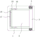
FIG. 1 is a sectional view of the present invention;
fig. 2 is a schematic view of the structure of the lamp body of the present invention;
fig. 3 is an enlarged view of a structure shown in fig. 1 according to the present invention.
Wherein: 1. a stationary case; 2. a lamp body; 3. mounting a plate; 4. a cavity; 5. a transverse plate; 6. a movable rod; 7. a movable plate; 8. clamping a plate; 9. a triangular clamping block; 10. a compression spring; 11. pulling the handle; 12. a chute; 13. a pulley; 14. a limiting groove; 15. a limiting block; 16. a limit tooth block; 17. a buffer sheet; 18. a buffer plate; 19. side plates.
Detailed Description
The technical solutions in the embodiments of the present invention will be described clearly and completely with reference to the accompanying drawings in the embodiments of the present invention, and it is obvious that the described embodiments are only some embodiments of the present invention, not all embodiments. Based on the embodiments in the present invention, all other embodiments obtained by a person skilled in the art without creative work belong to the protection scope of the present invention.
Please refer to fig. 1-3, a mounting structure of L ED corner lamp, including set casing 1, lamp body 2 and mounting panel 3, the inside swing joint of the side surface of lamp body 2 and set casing 1, the left side of mounting panel 3 and the right side fixed connection of lamp body 2, cavity 4 has all been seted up to inside roof and interior diapire on the right side of set casing 1, cavity 4's inside is including diaphragm 5, movable rod 6, movable plate 7 and cardboard 8, the left and right sides of diaphragm 5 respectively with the inner wall fixed connection on the left side of cavity 4 and right side, the side surface of movable rod 6 and the inside movable grafting of diaphragm 5, the side surface of movable plate 7 and the inside swing joint of cavity 4, and the top of movable plate 7 and the bottom fixed connection of movable rod 6, the top of movable rod 6 runs through the bottom of diaphragm 5 and extends to the top of diaphragm 5, the bottom of pulling handle 11 and the top overlap joint of diaphragm 5, the top of cardboard 8 and the bottom fixed connection of light body 7, the top of mounting plate 8 and the bottom fixed connection of mounting panel 7 have triangle 9, the bottom of fixed clamp block 9 and the bottom of fixed clamp plate 8 are all connected with the bottom of fixed slide groove 10, the fixed slide groove 10 and the fixed slide groove 2 and the fixed slide groove 10 are connected with the bottom of the fixed slide plate 2 and the fixed slide plate 2, the fixed slide groove 2 and the fixed slide groove 4, the bottom of the fixed slide groove 4 and the fixed slide groove 7, the fixed slide groove 10, the bottom of the fixed slide groove 7, the fixed slide groove 2 and the fixed slide groove 4 and the fixed slide groove 10, the bottom of the fixed slide groove 4 have the fixed slide groove 4, the bottom of the fixed slide groove 10, the bottom of the fixed slide groove 4 and the bottom of the fixed slide groove 10, the fixed slide groove 4 and the bottom of the fixed slide groove 2 and the fixed slide groove 4 respectively, the bottom of the fixed slide groove 10, the fixed slide groove 4, the bottom of the fixed slide groove 4 and the fixed slide groove 4 are connected with the bottom of the fixed slide groove 4, the bottom of the fixed slide groove 14, the fixed slide groove 2 and the fixed slide groove 4, the fixed slide groove 10, the bottom of the fixed slide groove 4.
When the lamp body 2 is moved to the leftmost side of the fixed shell 1, the movable plate 7 and the clamping plate 8 are pushed to move downwards through the elastic action of the extrusion spring 10, so that the triangular clamping block 9 is inserted into the triangular clamping groove, the position of the whole device is fixed, when the inside of the device is damaged, the pulling handles 11 are pulled towards two sides, the movable rod 6 drives the movable plate 7 and the clamping plate 8 to move towards two sides, the triangular clamping block 9 is separated from the inside of the triangular clamping groove, and the mounting plate 3 is pulled towards the right side to take out the lamp body 2 from the inside of the fixed shell 1, and then the inside of the lamp body 2 is convenient to overhaul and maintain.
Although embodiments of the present invention have been shown and described, it will be appreciated by those skilled in the art that changes, modifications, substitutions and alterations can be made in these embodiments without departing from the principles and spirit of the invention, the scope of which is defined in the appended claims and their equivalents.
Claims (7)
1. The utility model provides an L ED corner lamp's mounting structure, includes set casing (1), lamp body (2) and mounting panel (3), its characterized in that the inside swing joint of the side surface of lamp body (2) and set casing (1), the left side of mounting panel (3) and the right side fixed connection of lamp body (2), cavity (4) have all been seted up to interior roof and interior diapire on set casing (1) right side, the inside of cavity (4) is including diaphragm (5), movable rod (6), fly leaf (7) and cardboard (8), the left and right sides of diaphragm (5) respectively with the inner wall fixed connection on cavity (4) left side and right side, the inside activity grafting of the side surface and diaphragm (5) of movable rod (6), the inside swing joint of the side surface and cavity (4) of fly leaf (7), and the bottom fixed connection of the top and the movable rod (6) of fly leaf (7), the top and the bottom fixed connection of fly leaf (7) of cardboard (8), the top and the bottom fixed connection of the bottom of the pull spring (10) of the inside spring (10) of the left and right sides of the fixed connection of the slide leaf (7), the fixed connection of the triangle (10) of the fixed connection of the pulling spring (10), the inside push the both sides of the fixed connection of the board (5), the triangle (10).
2. The L ED corner lamp mounting structure according to claim 1, wherein a triangular clamping groove is formed in the bottom of the clamping plate (8), and one side of the triangular clamping block (9) far away from the mounting plate (3) is inserted into the triangular clamping groove.
3. An L ED corner lamp mounting structure, according to claim 1, wherein the top end of the movable rod (6) extends through the bottom of the cross plate (5) to the top of the cross plate (5), and the bottom of the pull handle (11) overlaps the top of the cross plate (5).
4. The L ED corner lamp mounting structure according to claim 1, wherein the cavity (4) has sliding grooves (12) on both sides, the movable plate (7) has pulleys (13) movably connected to both sides, and one side of the pulley (13) away from the movable plate (7) is slidably connected to the inside of the sliding groove (12).
5. The L ED corner lamp mounting structure according to claim 1, wherein the top and bottom of the right side of the fixing shell (1) are both provided with a limiting groove (14), the top and bottom of the left side of the mounting plate (3) are both fixedly connected with limiting blocks (15), and the left sides of the two limiting blocks (15) are respectively inserted into the two limiting grooves (14).
6. An L ED corner lamp mounting structure as claimed in claim 1, wherein the top and bottom walls of the fixed casing (1) are fixedly connected with limit tooth blocks (16).
7. An L ED corner lamp mounting structure as claimed in claim 1, wherein the fixed housing (1) includes a buffer plate (17), a buffer plate (18) and two side plates (19), the left side of the buffer plate (17) is fixedly connected with the inner wall of the left side of the fixed housing (1), the left side of the buffer plate (18) is fixedly connected with the right side of the buffer plate (17), the right side of the buffer plate (18) is overlapped with the left side of the lamp body (2), the two side plates (19) are respectively fixedly connected with the top and the bottom of the buffer plate (18), and the opposite sides of the two side plates (19) are respectively fixedly connected with the left side of the side surface of the lamp body (2).
Priority Applications (1)
| Application Number | Priority Date | Filing Date | Title |
|---|---|---|---|
| CN202020040613.9U CN211011240U (en) | 2020-01-09 | 2020-01-09 | Mounting structure of L ED corner lamp |
Applications Claiming Priority (1)
| Application Number | Priority Date | Filing Date | Title |
|---|---|---|---|
| CN202020040613.9U CN211011240U (en) | 2020-01-09 | 2020-01-09 | Mounting structure of L ED corner lamp |
Publications (1)
| Publication Number | Publication Date |
|---|---|
| CN211011240U true CN211011240U (en) | 2020-07-14 |
Family
ID=71474503
Family Applications (1)
| Application Number | Title | Priority Date | Filing Date |
|---|---|---|---|
| CN202020040613.9U Expired - Fee Related CN211011240U (en) | 2020-01-09 | 2020-01-09 | Mounting structure of L ED corner lamp |
Country Status (1)
| Country | Link |
|---|---|
| CN (1) | CN211011240U (en) |
-
2020
- 2020-01-09 CN CN202020040613.9U patent/CN211011240U/en not_active Expired - Fee Related
Similar Documents
| Publication | Publication Date | Title |
|---|---|---|
| CN218954752U (en) | A LED light that is easy to install and disassemble | |
| CN212661377U (en) | Auxiliary device that architectural design drawing was used | |
| CN201802284U (en) | Fixed screen window provided with magnetic connecting mechanism | |
| CN210050689U (en) | Clamping type lamp bracket ceiling lamp | |
| CN211083762U (en) | Double-sided light-emitting ultrathin L ED lamp box | |
| CN223718748U (en) | Processing platform for manufacturing illumination lamp | |
| CN219587029U (en) | Backlight lamp area furred ceiling structure | |
| CN211573851U (en) | Fan lamp remote controller | |
| CN220338168U (en) | LED lighting lamp box convenient to installation | |
| CN210860838U (en) | Down lamp convenient to installation | |
| CN219773930U (en) | Sliding door assembled guide rail | |
| CN219902772U (en) | Drilling equipment of intelligent lamps and lanterns installation | |
| CN218820070U (en) | Metal down lamp | |
| CN216307582U (en) | LED ultra-thin down lamp | |
| CN218267983U (en) | Protective cover structure for mechanical equipment | |
| CN219160223U (en) | High-light-efficiency LED module | |
| CN223470138U (en) | Regulation structure and spotlight thereof | |
| CN214745229U (en) | Handrail lamp free of tool installation | |
| CN221483498U (en) | Make things convenient for frame device of LED panel light installation | |
| CN211083712U (en) | A flexible LED lamp device that does not break off and is easy to install a circuit board | |
| CN219411591U (en) | Grille aluminum alloy panel | |
| CN213810493U (en) | Energy-conserving lighting apparatus of using of bridge | |
| CN216844582U (en) | Embedded lamp tube power supply driver mounting structure and lamp | |
| CN217195188U (en) | A workstation for assembling new forms of energy equipment | |
| CN219775920U (en) | Air outlet plate of fresh air system |
Legal Events
| Date | Code | Title | Description |
|---|---|---|---|
| GR01 | Patent grant | ||
| GR01 | Patent grant | ||
| CF01 | Termination of patent right due to non-payment of annual fee | ||
| CF01 | Termination of patent right due to non-payment of annual fee |
Granted publication date: 20200714 |