CN210996578U - Double-end boring machine - Google Patents
Double-end boring machine Download PDFInfo
- Publication number
- CN210996578U CN210996578U CN201922020906.0U CN201922020906U CN210996578U CN 210996578 U CN210996578 U CN 210996578U CN 201922020906 U CN201922020906 U CN 201922020906U CN 210996578 U CN210996578 U CN 210996578U
- Authority
- CN
- China
- Prior art keywords
- boring machine
- threaded rod
- fixing frame
- fixedly connected
- double
- Prior art date
- Legal status (The legal status is an assumption and is not a legal conclusion. Google has not performed a legal analysis and makes no representation as to the accuracy of the status listed.)
- Expired - Fee Related
Links
Images


Landscapes
- Drilling And Boring (AREA)
Abstract
本实用新型公开了一种双头镗床,包括镗床基座,所述镗床基座的两端设有水平放置的第一伺服气缸,镗床基座中部开设有两个滑动槽,每个滑动槽的顶端滑动安装有距离调节底座,距离调节底座与对应第一伺服气缸的输出轴固定连接;所述调节底座向上依次设置有4个导向杆、第一螺纹杆、主轴安装架、固定板、固定架以及高度调节伺服电机,4个导向杆、第一螺纹杆以及主轴安装架位于调节底座和固定板之间,4个导向杆和第一螺纹杆穿过主轴安装架与固定板连接。本实用新型结构巧妙,使用方便,能够顶侧和靠近工作人员的一侧挡住飞溅的铁屑,使得加工更加安全,放置高温铁屑飞到工作人员的身上造成安全隐患,且调节方便,能够加工各种不同加工要求的工件。
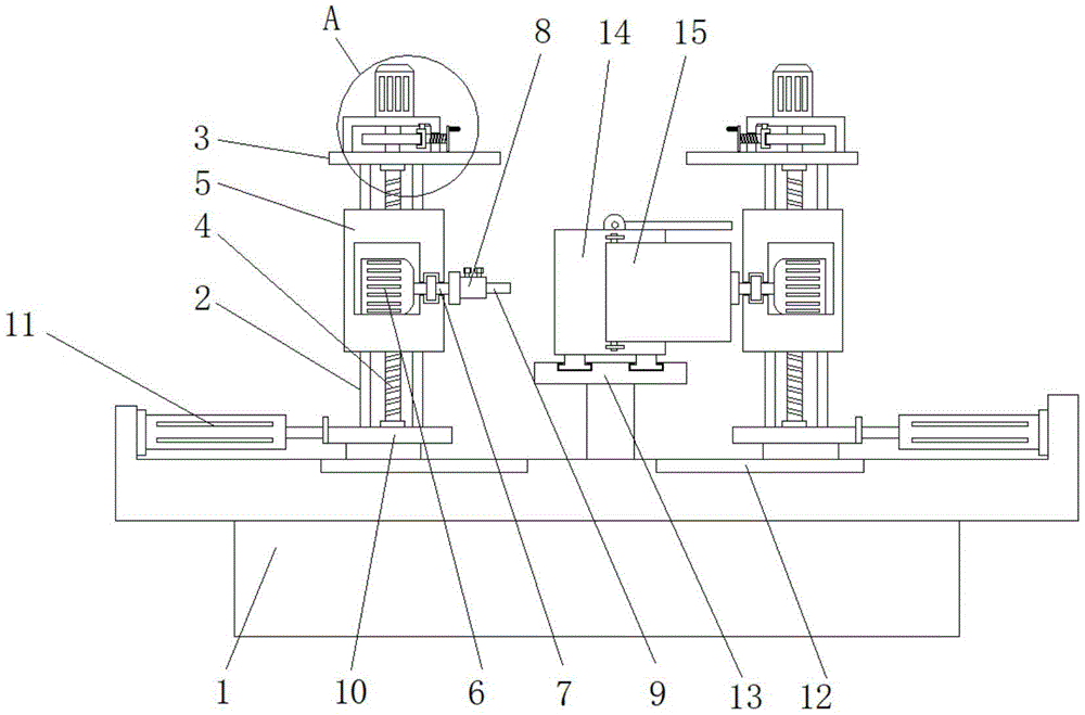
The utility model discloses a double-headed boring machine, which comprises a boring machine base, two ends of the boring machine base are provided with first servo cylinders placed horizontally, and two sliding grooves are arranged in the middle of the boring machine base. A distance adjustment base is slidably installed at the top, and the distance adjustment base is fixedly connected with the output shaft corresponding to the first servo cylinder; the adjustment base is provided with 4 guide rods, a first threaded rod, a spindle mounting frame, a fixing plate, and a fixing frame in order upwards. And the height adjustment servo motor, the 4 guide rods, the first threaded rod and the spindle mounting bracket are located between the adjustment base and the fixing plate, and the 4 guiding rods and the first threaded rod are connected to the fixing plate through the spindle mounting bracket. The utility model is ingenious in structure and convenient to use, and can block the splashing iron filings on the top side and the side close to the staff, so that the processing is safer. Various workpieces with different processing requirements.
Description
技术领域technical field
本实用新型属于双头镗床技术领域,具体涉及一种双头镗床。The utility model belongs to the technical field of double-end boring machines, in particular to a double-end boring machine.
背景技术Background technique
镗床主要用镗刀对工件已有的预制孔进行镗削的机床。通常,镗刀旋转为主运动,镗刀或工件的移动为进给运动。它主要用于加工高精度孔或一次定位完成多个孔的精加工,此外还可以从事与孔精加工有关的其他加工面的加工。使用不同的刀具和附件还可进行钻削、铣削、切它的加工精度和表面质量要高于钻床。镗床是大型箱体零件加工的主要设备。螺纹及加工外圆和端面等。双头镗床即为具有两个主轴的镗床,能够从工件的两侧分别对工件进行加工。The boring machine mainly uses the boring tool to boring the existing prefabricated holes of the workpiece. Usually, the rotation of the boring tool is the main motion, and the movement of the boring tool or the workpiece is the feed motion. It is mainly used to process high-precision holes or finish machining of multiple holes at one time, and it can also be engaged in the machining of other machining surfaces related to hole finishing. Using different tools and accessories can also be used for drilling, milling, and cutting. Its machining accuracy and surface quality are higher than those of a drilling machine. The boring machine is the main equipment for processing large box parts. Thread and processing external circle and end face, etc. A double-head boring machine is a boring machine with two spindles, which can process the workpiece from both sides of the workpiece.
双头镗床在对工件加工时会产生飞溅的高温铁屑,现有的双头镗床大多不具备防止铁屑飞溅的机构,高温铁屑很容易飞溅到工作人员身上,从而对工作人员的安全造成隐患。The double-head boring machine will produce high-temperature iron scraps that splash when machining the workpiece. Most of the existing double-head boring machines do not have a mechanism to prevent the iron scraps from splashing. hidden danger.
实用新型内容Utility model content
本实用新型的目的在于提供一种双头镗床,以解决上述背景技术中提出的问题。The purpose of the present invention is to provide a double-head boring machine to solve the problems raised in the above background technology.
为实现上述目的,本实用新型提供如下技术方案:一种双头镗床,包括镗床基座,所述镗床基座的两端设有水平放置的第一伺服气缸,镗床基座中部开设有两个滑动槽,每个滑动槽的顶端滑动安装有距离调节底座,距离调节底座与对应第一伺服气缸的输出轴固定连接;所述调节底座向上依次设置有4个导向杆、第一螺纹杆、主轴安装架、固定板、固定架以及高度调节伺服电机,4个导向杆、第一螺纹杆以及主轴安装架位于调节底座和固定板之间,4个导向杆和第一螺纹杆穿过主轴安装架与固定板连接,其中第一螺纹杆位于4个导向杆中间;所述主轴安装架上横向固定安装有主轴驱动电机;所述高度调节伺服电机的输出轴与第一螺纹杆固定连接,两个所述主轴安装架相互靠近的一侧转动安装有主轴,主轴驱动电机的输出轴与主轴固定连接,两根主轴相互靠近的一侧焊接有夹具,夹具上固定安装有刀具;镗床基座的中间位置固定安装有滑轨,滑轨上滑动安装有工件固定框,工件固定框与所述刀具配合工作;所述滑轨的顶端还固定连接有水平设置的第二伺服气缸,第二伺服气缸的输出轴与工件固定框固定连接,工件固定框的顶侧和远离第二伺服气缸的一侧均铰接安装有挡板。In order to achieve the above purpose, the utility model provides the following technical solutions: a double-head boring machine, comprising a boring machine base, two ends of the boring machine base are provided with first servo cylinders placed horizontally, and two horizontally placed first servo cylinders are arranged in the middle of the boring machine base. A sliding groove, the top of each sliding groove is slidably installed with a distance adjustment base, and the distance adjustment base is fixedly connected with the output shaft of the corresponding first servo cylinder; the adjustment base is provided with 4 guide rods, a first threaded rod, and a main shaft in sequence upward. The mounting bracket, the fixing plate, the fixing bracket and the height adjustment servo motor, the 4 guide rods, the first threaded rod and the spindle mounting bracket are located between the adjustment base and the fixing plate, and the 4 guiding rods and the first threaded rod pass through the spindle mounting bracket Connected with the fixing plate, wherein the first threaded rod is located in the middle of the four guide rods; the spindle drive motor is fixedly installed horizontally on the spindle mounting frame; the output shaft of the height adjustment servo motor is fixedly connected with the first threaded rod, and the two A main shaft is rotatably installed on the mutually close side of the main shaft mounting frame, the output shaft of the main shaft drive motor is fixedly connected with the main shaft, a clamp is welded on the side of the two main shafts close to each other, and a tool is fixedly installed on the clamp; the middle of the boring machine base A slide rail is fixedly installed on the slide rail, a workpiece fixing frame is slidably installed on the slide rail, and the workpiece fixing frame cooperates with the tool; the top of the slide rail is also fixedly connected with a horizontally arranged second servo cylinder. The output shaft is fixedly connected with the workpiece fixing frame, and baffle plates are hingedly installed on the top side of the workpiece fixing frame and the side away from the second servo cylinder.
优选的,所述固定架上开设有第二螺纹孔,第二螺纹孔内螺纹安装有水平设置的第二螺纹杆,第二螺纹杆的一端延伸至固定架的内部且转动连接有锁紧件,固定架上开设有水平设置的导向槽,锁紧件的顶端延伸至导向槽内,第一螺纹杆的外侧位于固定架内部滚动连接有锁紧圆盘。Preferably, the fixing frame is provided with a second threaded hole, the second threaded hole is threadedly mounted with a second threaded rod arranged horizontally, and one end of the second threaded rod extends into the interior of the fixing frame and is rotatably connected with a locking member The fixing frame is provided with a horizontally arranged guide groove, the top end of the locking piece extends into the guide groove, and the outer side of the first threaded rod is located inside the fixing frame and is connected with a locking disc in rolling connection.
优选的,所述锁紧件靠近锁紧圆盘的一侧开设有锁紧槽,锁紧圆盘的周边延伸至锁紧槽内。Preferably, a locking groove is provided on a side of the locking member close to the locking disc, and the periphery of the locking disc extends into the locking groove.
优选的,所述第二螺纹杆远离锁紧件的一端固定连接有转动把手。Preferably, a rotating handle is fixedly connected to one end of the second threaded rod away from the locking member.
优选的,所述工件固定框的顶端内壁上固定安装有竖直设置的夹紧气缸,夹紧气缸的输出轴固定连接有夹紧件。Preferably, a vertically arranged clamping cylinder is fixedly installed on the inner wall of the top end of the workpiece fixing frame, and a clamping member is fixedly connected to the output shaft of the clamping cylinder.
优选的,所述夹紧件的底端与工件固定框的底端内壁上均固定连接有橡胶垫。Preferably, rubber pads are fixedly connected to the bottom end of the clamping piece and the inner wall of the bottom end of the workpiece fixing frame.
与现有技术相比,本实用新型的有益效果是:Compared with the prior art, the beneficial effects of the present utility model are:
1.加工时,挡板能够手动转动至准备加工的一侧,然后从顶侧和靠近工作人员的一侧挡住飞溅的铁屑,使得加工更加安全,放置高温铁屑飞到工作人员的身上造成安全隐患;1. During processing, the baffle can be manually rotated to the side to be processed, and then the splashed iron filings are blocked from the top side and the side close to the worker, making the machining safer. Security risks;
2.通过高度调节伺服电机能够驱动主轴安装架升降,转动转动把手能够将主轴安装架的高度固定住,从而在竖直方向上调节刀具与加工工件的相对位置,通过第二伺服气缸能够推动工件水平移动,从而从水平方向上调节刀具与加工工件的相对位置,使得镗床能够加工各种不同加工要求的工件;2. The servo motor can drive the spindle mounting frame to rise and fall through the height adjustment, and the height of the spindle mounting frame can be fixed by turning the handle, so as to adjust the relative position of the tool and the workpiece in the vertical direction, and the workpiece can be pushed by the second servo cylinder Horizontal movement, so as to adjust the relative position of the tool and the workpiece from the horizontal direction, so that the boring machine can process various workpieces with different processing requirements;
本实用新型结构巧妙,使用方便,能够顶侧和靠近工作人员的一侧挡住飞溅的铁屑,使得加工更加安全,放置高温铁屑飞到工作人员的身上造成安全隐患,且调节方便,能够加工各种不同加工要求的工件。The utility model is ingenious in structure and convenient to use, and can block the splashing iron filings on the top side and the side close to the staff, so that the processing is more secure. Various workpieces with different processing requirements.
附图说明Description of drawings
图1为本实用新型的主视图;Fig. 1 is the front view of the utility model;
图2为本实用新型的工件固定框右视图;Fig. 2 is the right side view of the workpiece fixing frame of the present invention;
图3为本实用新型的A位置放大示意图。FIG. 3 is an enlarged schematic diagram of position A of the present invention.
图中:1、镗床基座;2、导向杆;3、固定板;4、第一螺纹杆;5、主轴安装架;6、主轴驱动电机;7、主轴;8、夹具;9、刀具;10、距离调节底座;11、第一伺服气缸;12、滑动槽;13、滑轨;14、工件固定框;15、挡板;16、夹紧气缸;17、夹紧件;18、橡胶垫;19、第二伺服气缸;20、固定架;21、高度调节伺服电机;22、锁紧圆盘;23、第二螺纹杆;24、导向槽;25、锁紧件;26、转动把手。In the figure: 1. Boring machine base; 2. Guide rod; 3. Fixed plate; 4. First threaded rod; 5. Spindle mounting frame; 6. Spindle drive motor; 7. Spindle; 8. Fixture; 9. Tool; 10. Distance adjustment base; 11. First servo cylinder; 12. Sliding groove; 13. Slide rail; 14. Workpiece fixing frame; 15. Baffle plate; 16. Clamping cylinder; 17. Clamping piece; 18. Rubber pad ; 19, the second servo cylinder; 20, the fixed frame; 21, the height adjustment servo motor; 22, the locking disc; 23, the second threaded rod; 24, the guide groove;
具体实施方式Detailed ways
下面结合实施例对本实用新型做进一步的描述。The present utility model will be further described below in conjunction with the embodiments.
以下实施例用于说明本实用新型,但不能用来限制本实用新型的保护范围。实施例中的条件可以根据具体条件做进一步的调整,在本实用新型的构思前提下对本实用新型的方法简单改进都属于本实用新型要求保护的范围。The following examples are used to illustrate the present utility model, but cannot be used to limit the protection scope of the present utility model. Conditions in the examples can be further adjusted according to specific conditions, and simple improvements to the method of the present invention under the concept of the present invention all belong to the scope of protection of the present invention.
请参阅图1-3,本实用新型提供一种双头镗床技术方案:包括镗床基座1,镗床基座1的顶端两侧均设有固定连接有水平设置的第一伺服气缸11,镗床基座1的顶端位于两个第一伺服气缸11之间开设有两个滑动槽12,滑动槽12的顶端滑动安装有距离调节底座10,两块距离调节底座10相互远离的一侧分别对应与两个第一伺服气缸11的输出轴固定连接,距离调节底座10的顶端四个拐角均固定连接有竖直设置的导向杆2,四根导向杆2的顶端之间固定连接有固定板3,固定板3与距离调节底座10之间还设有主轴安装架5,主轴安装架5上开设有四个导向孔,四根导向杆2分别对应通过四个导向孔贯穿主轴安装架5,固定板3与距离调节底座10之间还转动安装有竖直设置的第一螺纹杆4,主轴安装架5上开设有第一螺纹孔,第一螺纹杆4通过第一螺纹孔贯穿主轴安装架5,主轴安装架5上固定安装有主轴驱动电机6,两个主轴安装架5相互靠近的一侧转动安装有主轴7,主轴驱动电机6的输出轴与主轴7固定连接,两根主轴7相互靠近的一侧焊接有夹具8,夹具8上固定安装有刀具9,固定板3的顶端固定连接有固定架20,固定架20的顶端固定安装有高度调节伺服电机21,高度调节伺服电机21的输出轴与第一螺纹杆4固定连接,镗床基座1的顶端中间位置固定安装有滑轨13,滑轨13的顶端滑动安装有工件固定框14,滑轨13的顶端还固定连接有水平设置的第二伺服气缸19,第二伺服气缸19的输出轴与工件固定框14固定连接,工件固定框14的顶侧和远离第二伺服气缸19的一侧均铰接安装有挡板15。Please refer to FIGS. 1-3 , the present utility model provides a technical scheme of a double-head boring machine: it includes a
其中,固定架20上开设有第二螺纹孔,第二螺纹孔内螺纹安装有水平设置的第二螺纹杆23,第二螺纹杆23的一端延伸至固定架20的内部且转动连接有锁紧件25,固定架20上开设有水平设置的导向槽24,锁紧件25的顶端延伸至导向槽24内,第一螺纹杆4的外侧位于固定架20内部滚动连接有锁紧圆盘22,转动第一螺纹杆4能够向左推动锁紧件25,使得锁紧件25与锁紧圆盘22紧紧的压在一起,从而达到锁紧第一螺纹杆4的效果,从而使得主轴安装架5的位置被锁紧。The fixing
其中,锁紧件25靠近锁紧圆盘22的一侧开设有锁紧槽,锁紧圆盘22的周边延伸至锁紧槽内,锁紧件25向左移动可将锁紧圆盘22卡在锁紧槽内,锁紧件25和锁紧圆盘22采用表面凹凸不平的摩擦材料。A locking groove is formed on the side of the locking
其中,第二螺纹杆23远离锁紧件25的一端固定连接有转动把手26,通过转动把手26能够省力的转动第二螺纹杆23。A
其中,工件固定框14的顶端内壁上固定安装有竖直设置的夹紧气缸16,夹紧气缸16的输出轴固定连接有夹紧件17,夹紧气缸16伸长能够推动夹紧件17向下移动压紧工件。Among them, a vertically arranged clamping
其中,夹紧件17的底端与工件固定框14的底端内壁上均固定连接有橡胶垫18,橡胶垫18起到缓冲和增加摩擦的效果。A
本实用新型的工作原理及使用流程:将工件放在工件固定框14内,通过夹紧件17夹紧固定,两个刀具9能够分别从两侧对工件进行加工,通过第一伺服气缸11能够推动主轴安装架5水平移动,从而推动刀具9靠近工件上的加工位置,通过高度调节伺服电机21驱动第一螺纹杆4转动能够带动主轴安装架5升降,从而能够根据工件上的待加工位置调节刀具9的高度,通过第二伺服气缸19能够推动工件固定框14水平移动,从而能调节工件上的待加工位置相对于刀具9的水平位置,主轴驱动电机6能够带动刀具9转动对工件加工,挡板15能够手动转动至准备加工的一侧,然后从顶侧和靠近工作人员的一侧挡住飞溅的铁屑,使得加工更加安全。The working principle and use process of the utility model: the workpiece is placed in the
尽管已经示出和描述了本实用新型的实施例,对于本领域的普通技术人员而言,可以理解在不脱离本实用新型的原理和精神的情况下可以对这些实施例进行多种变化、修改、替换和变型,本实用新型的范围由所附权利要求及其等同物限定。Although the embodiments of the present invention have been shown and described, it will be understood by those skilled in the art that various changes and modifications can be made to these embodiments without departing from the principles and spirit of the present invention , alternatives and modifications, the scope of the present invention is defined by the appended claims and their equivalents.
Claims (6)
Priority Applications (1)
| Application Number | Priority Date | Filing Date | Title |
|---|---|---|---|
| CN201922020906.0U CN210996578U (en) | 2019-11-20 | 2019-11-20 | Double-end boring machine |
Applications Claiming Priority (1)
| Application Number | Priority Date | Filing Date | Title |
|---|---|---|---|
| CN201922020906.0U CN210996578U (en) | 2019-11-20 | 2019-11-20 | Double-end boring machine |
Publications (1)
| Publication Number | Publication Date |
|---|---|
| CN210996578U true CN210996578U (en) | 2020-07-14 |
Family
ID=71502345
Family Applications (1)
| Application Number | Title | Priority Date | Filing Date |
|---|---|---|---|
| CN201922020906.0U Expired - Fee Related CN210996578U (en) | 2019-11-20 | 2019-11-20 | Double-end boring machine |
Country Status (1)
| Country | Link |
|---|---|
| CN (1) | CN210996578U (en) |
Cited By (6)
| Publication number | Priority date | Publication date | Assignee | Title |
|---|---|---|---|---|
| CN112496382A (en) * | 2020-11-13 | 2021-03-16 | 江苏华阳重工股份有限公司 | Rudder blade machining device convenient to mount and dismount |
| CN112692331A (en) * | 2021-01-07 | 2021-04-23 | 六安市龙兴汽车零部件有限公司 | New forms of energy gearbox casing bore hole device |
| CN112756647A (en) * | 2020-12-30 | 2021-05-07 | 萍乡市长峻特种材料铸造有限公司 | Tapping equipment is used in metal casting processing |
| CN113290271A (en) * | 2021-06-01 | 2021-08-24 | 安徽震祥精工科技有限公司 | A portable bore hole device for accessories site operation |
| CN114178937A (en) * | 2021-11-11 | 2022-03-15 | 安徽亚珠金刚石股份有限公司 | Artificial diamond composite sheet lathe tool grinding device |
| CN114227362A (en) * | 2021-12-30 | 2022-03-25 | 杭州临安雄风机械有限公司 | Boring machine for blind hole machining |
-
2019
- 2019-11-20 CN CN201922020906.0U patent/CN210996578U/en not_active Expired - Fee Related
Cited By (6)
| Publication number | Priority date | Publication date | Assignee | Title |
|---|---|---|---|---|
| CN112496382A (en) * | 2020-11-13 | 2021-03-16 | 江苏华阳重工股份有限公司 | Rudder blade machining device convenient to mount and dismount |
| CN112756647A (en) * | 2020-12-30 | 2021-05-07 | 萍乡市长峻特种材料铸造有限公司 | Tapping equipment is used in metal casting processing |
| CN112692331A (en) * | 2021-01-07 | 2021-04-23 | 六安市龙兴汽车零部件有限公司 | New forms of energy gearbox casing bore hole device |
| CN113290271A (en) * | 2021-06-01 | 2021-08-24 | 安徽震祥精工科技有限公司 | A portable bore hole device for accessories site operation |
| CN114178937A (en) * | 2021-11-11 | 2022-03-15 | 安徽亚珠金刚石股份有限公司 | Artificial diamond composite sheet lathe tool grinding device |
| CN114227362A (en) * | 2021-12-30 | 2022-03-25 | 杭州临安雄风机械有限公司 | Boring machine for blind hole machining |
Similar Documents
| Publication | Publication Date | Title |
|---|---|---|
| CN106078361B (en) | The vertical compound multi-panel processing center machine tool that crouches of one kind | |
| CN213917462U (en) | Aluminum veneer polishing equipment | |
| CN205950413U (en) | Found compound multiaspect machining center lathe that crouches | |
| CN105328230B (en) | A kind of cylinder reboring machine and its method of double cutter heads | |
| CN209754598U (en) | clamping device for machine tool machining | |
| CN105500008A (en) | Milling and grinding combined machine tool | |
| CN211249228U (en) | A high positioning milling machine | |
| CN216098172U (en) | Simple polishing and cutting integrated machine | |
| CN211101755U (en) | Special machine tool for butt milling | |
| CN103551861B (en) | Numerical control machining center machine tool | |
| CN107282961A (en) | A kind of miniature workpiece composite processing machine tool | |
| CN218639116U (en) | Chamfering tool of vertical milling machine | |
| CN212470547U (en) | A drilling and milling machine table structure and a drilling and milling machine | |
| CN218696374U (en) | A positioning fixture for CNC gantry milling machine processing | |
| CN214603036U (en) | Milling and tapping machine for metal products | |
| CN215035248U (en) | A vertical and horizontal composite machining center | |
| CN205020914U (en) | Large -scale integral key shaft processingequipment | |
| CN206326698U (en) | A kind of timber horizontal Machining centers | |
| CN111618610A (en) | A drilling and milling machine table structure and a drilling and milling machine | |
| CN212071258U (en) | Drilling workbench for machining | |
| CN211565111U (en) | Diversified adjustable blade disc | |
| CN217192801U (en) | A high-automation dual-spindle CNC machine tool | |
| CN217254557U (en) | Ring type part adding type special clamp for numerical control vertical lathe | |
| CN215788547U (en) | Gantry machine tool with operation protection structure | |
| CN221817379U (en) | A cylinder head machining boring machine |
Legal Events
| Date | Code | Title | Description |
|---|---|---|---|
| GR01 | Patent grant | ||
| GR01 | Patent grant | ||
| TR01 | Transfer of patent right | ||
| TR01 | Transfer of patent right |
Effective date of registration: 20230714 Address after: 311800 Jiangzao Village, Yaojiang Town, Zhuji City, Shaoxing, Zhejiang Province (next to the gas station) Patentee after: Zhejiang Wanke Machinery Co.,Ltd. Address before: No. 127, Wanda Middle Road, Wenyan Town, Xiaoshan District, Hangzhou, Zhejiang 311258 Patentee before: Hangzhou Litong Machinery Co.,Ltd. |
|
| CF01 | Termination of patent right due to non-payment of annual fee | ||
| CF01 | Termination of patent right due to non-payment of annual fee |
Granted publication date: 20200714 |