CN210992085U - Neurosurgery nursing drainage frame - Google Patents
Neurosurgery nursing drainage frame Download PDFInfo
- Publication number
- CN210992085U CN210992085U CN201921435591.XU CN201921435591U CN210992085U CN 210992085 U CN210992085 U CN 210992085U CN 201921435591 U CN201921435591 U CN 201921435591U CN 210992085 U CN210992085 U CN 210992085U
- Authority
- CN
- China
- Prior art keywords
- block
- drainage
- placement
- rack
- fixing
- Prior art date
- Legal status (The legal status is an assumption and is not a legal conclusion. Google has not performed a legal analysis and makes no representation as to the accuracy of the status listed.)
- Expired - Fee Related
Links
Images


Landscapes
- Infusion, Injection, And Reservoir Apparatuses (AREA)
Abstract
本实用新型提供一种神经外科护理引流架。所述神经外科护理引流架,包括:底座、放置组件和放置架;安装管,所述安装管固定于所述底座的顶部;调节组件,所述调节组件设置于所述安装管的内部。本实用新型提供的神经外科护理引流架具有通过在内螺纹管的表面设置刻度线,并配合电机驱动丝杆,带动内螺纹管向上移动,进行调节其高度,调节精度高,通过设置放置组件和放置架可以对引流袋或者引流瓶进行放置限位,使引流袋或者引流瓶不会晃动固定稳定,且通过限位环对输液管进行限位,防止输液管折起,和晃动,影响病人输液治疗,保证病人引流的稳定性,且放置架和放置盒与顶部固定板安装和拆卸操作简单方便,可以适用引流瓶和引流袋,适用性强。
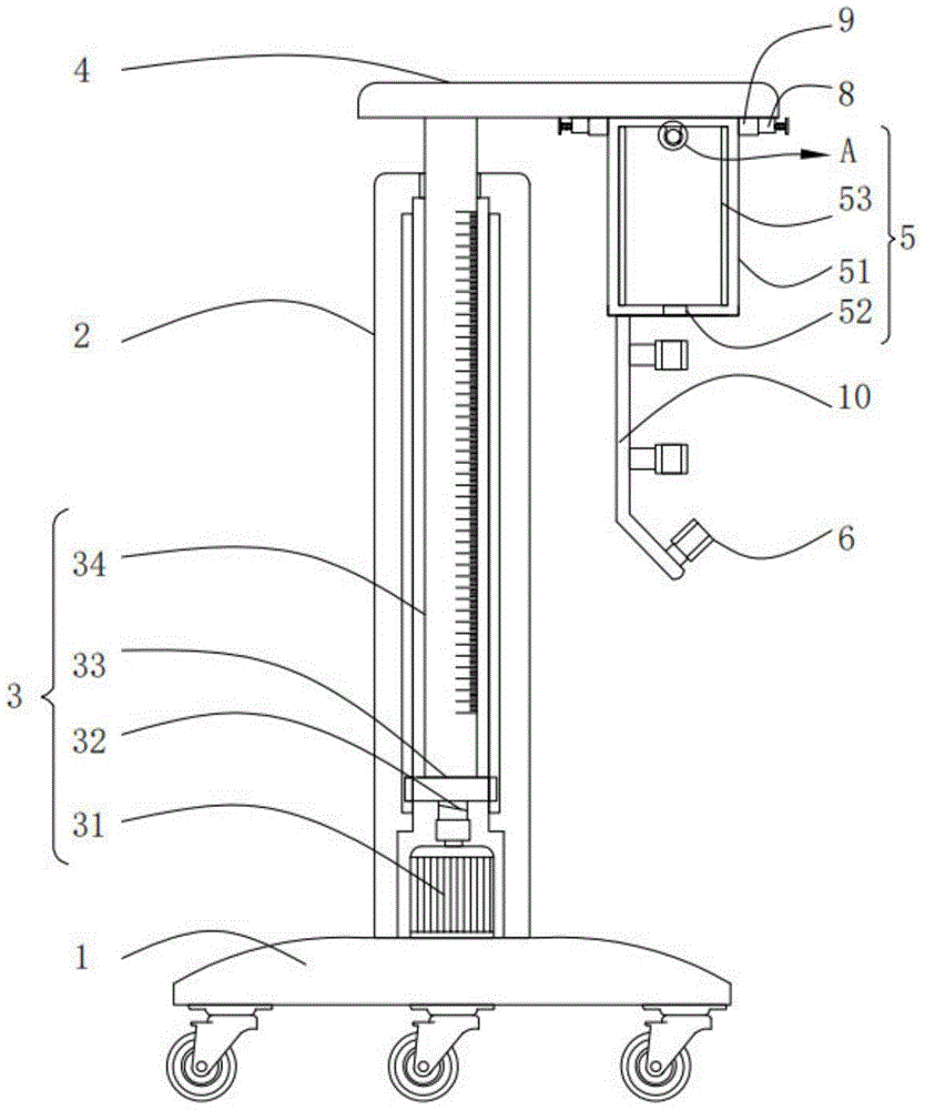
The utility model provides a neurosurgery nursing drainage rack. The neurosurgery nursing drainage rack includes: a base, a placement component and a placement rack; an installation tube, which is fixed on the top of the base; and an adjustment component, which is arranged inside the installation tube. The neurosurgery nursing and drainage rack provided by the utility model has a scale line arranged on the surface of the inner threaded pipe, and cooperates with a motor to drive a screw rod to drive the inner threaded pipe to move upward to adjust its height, and the adjustment accuracy is high. The placement rack can limit the drainage bag or drainage bottle, so that the drainage bag or drainage bottle will not be shaken and fixed and stable, and the infusion tube is limited by the limit ring to prevent the infusion tube from folding and shaking, which will affect the patient's infusion. Treatment, to ensure the stability of patient drainage, and the installation and removal of the placement rack and the placement box and the top fixing plate are simple and convenient, and can be applied to drainage bottles and drainage bags, with strong applicability.
Description
技术领域technical field
本实用新型涉及医疗器械的领域,尤其涉及一种神经外科护理引流架。The utility model relates to the field of medical instruments, in particular to a neurosurgery nursing drainage rack.
背景技术Background technique
神经外科是外科学中的一个分支,是在外科学以手术为主要治疗手段的基础上,应用独特的神经外科学研究方法,研究人体神经系统,如脑、脊髓和周围神经系统,以及与之相关的附属机构,如颅骨、头皮、脑血管脑膜等结构的损伤、炎症、肿瘤、畸形和某些遗传代谢障碍或功能紊乱疾病。Neurosurgery is a branch of surgery that applies unique neurosurgery research methods on the basis of surgery as the main treatment method to study the human nervous system, such as the brain, spinal cord and peripheral nervous system, and related Affiliated organs, such as skull, scalp, cerebrovascular meninges and other structural damage, inflammation, tumors, deformities and certain genetic metabolic disorders or functional disorders.
神经外科临床上在给病人进行神经外科手术引流时,需要使用到引流架,引流管的最高点要位于病人外耳道上方的15厘米处,确保引流时一定的脑室内压力,且引流液一般装于引流袋或者引流瓶,现有引流袋或者引流瓶放置在引流架在上时,通常是挂在引流架上的,并不稳定,引流袋或者引流瓶容易晃动,引流袋晃动会带动引流管动,影响病人的正常治疗,让病人感到不适。Neurosurgery clinically needs to use a drainage rack when performing neurosurgical drainage for patients. The highest point of the drainage tube should be located 15 cm above the patient's external auditory canal to ensure a certain intraventricular pressure during drainage. Drainage bag or drainage bottle. When the existing drainage bag or drainage bottle is placed on the drainage rack, it is usually hung on the drainage rack and is unstable. The drainage bag or drainage bottle is easy to shake, and the shaking of the drainage bag will drive the drainage tube to move. , affecting the normal treatment of the patient and making the patient feel uncomfortable.
因此,有必要提供一种神经外科护理引流架解决上述技术问题。Therefore, it is necessary to provide a neurosurgery nursing drainage rack to solve the above technical problems.
实用新型内容Utility model content
本实用新型提供一种神经外科护理引流架,解决了现有引流袋或者引流瓶放置在引流架在上时,不能稳定放置的问题。The utility model provides a neurosurgery nursing drainage rack, which solves the problem that the existing drainage bag or drainage bottle cannot be placed stably when the drainage rack is placed on the drainage rack.
为解决上述技术问题,本实用新型提供的神经外科护理引流架,包括:底座、放置组件和放置架;In order to solve the above technical problems, the neurosurgery nursing drainage rack provided by the present invention includes: a base, a placement component and a placement rack;
安装管,所述安装管固定于所述底座的顶部;an installation pipe, which is fixed on the top of the base;
调节组件,所述调节组件设置于所述安装管的内部,所述调节组件包括电机,所述电机输出轴的一端通过联轴器固定连接有丝杆,所述丝杆的表面螺纹连接有内螺纹管,所述内螺纹管的顶端贯穿所述安装管且延伸至安装管的外部;Adjustment assembly, the adjustment assembly is arranged inside the installation pipe, the adjustment assembly includes a motor, one end of the output shaft of the motor is fixedly connected with a screw rod through a coupling, and the surface of the screw rod is threadedly connected with an inner screw a threaded pipe, the top end of the internally threaded pipe penetrates the installation pipe and extends to the outside of the installation pipe;
顶部固定板,所述顶部固定板固定于所述内螺纹管的顶端且位于所述安装管的外部;a top fixing plate, the top fixing plate is fixed on the top end of the internally threaded pipe and is located outside the installation pipe;
两个固定组件,两个所述固定组件分别固定于所述顶部固定板的底部的两侧;two fixing assemblies, the two fixing assemblies are respectively fixed on both sides of the bottom of the top fixing plate;
所述放置组件包括放置盒,所述放置盒和所述放置架两侧的顶部均固定连接有卡接组件;The placement assembly includes a placement box, and the tops of both sides of the placement box and the placement rack are fixedly connected with snap-fit assemblies;
两个折形板,两个所述折形板分别固定于放置盒和放置架的底部的一侧;two folded plates, the two folded plates are respectively fixed on one side of the bottom of the placing box and the placing rack;
多个限位环,多个所述限位环通过固定件固定于所述折形板上。A plurality of limit rings, the plurality of limit rings are fixed on the folded plate by fixing pieces.
优选的,所述内螺纹管表面的底部套设有滑块,所述滑块的两侧分别与所述安装管内壁的两侧滑动连接,所述内螺纹管的表面设置有刻度线。Preferably, a sliding block is sleeved on the bottom of the surface of the inner threaded pipe, two sides of the sliding block are respectively slidably connected with both sides of the inner wall of the installation pipe, and a scale line is provided on the surface of the inner threaded pipe.
优选的,所述放置盒内壁的左右两侧均粘接有海绵块,所述放置盒内壁的顶部固定连接有卡环,所述卡环的右上侧设置有活动扣,所述放置盒底部的中间开设有通孔。Preferably, sponge blocks are adhered to the left and right sides of the inner wall of the placement box, a snap ring is fixedly connected to the top of the inner wall of the placement box, a movable buckle is arranged on the upper right side of the snap ring, and the bottom of the placement box is provided with a snap ring. A through hole is opened in the middle.
优选的,所述限位环的一侧设置有开口,所述限位环的内表面粘接有海绵垫。Preferably, one side of the limiting ring is provided with an opening, and a sponge pad is adhered to the inner surface of the limiting ring.
优选的,所述固定组件包括固定块,所述固定块的一侧开设有卡槽,所述卡槽内表面的顶部和底部之间滑动连接有推动块,所述推动块的一侧固定连接有连接杆,所述连接杆的一端贯穿所述固定块且延伸至所述固定块的外部。Preferably, the fixing assembly includes a fixing block, one side of the fixing block is provided with a slot, a push block is slidably connected between the top and the bottom of the inner surface of the slot, and one side of the push block is fixedly connected There is a connecting rod, and one end of the connecting rod penetrates the fixing block and extends to the outside of the fixing block.
优选的,所述连接杆的一端且位于所述固定块的外部固定连接有按压块,所述按压块的一侧与固定块之间且位于所述连接杆的表面固定连接有第一弹性件。Preferably, a pressing block is fixedly connected to one end of the connecting rod and is located outside the fixing block, and a first elastic member is fixedly connected between one side of the pressing block and the fixing block and located on the surface of the connecting rod .
优选的,所述卡接组件包括卡接块,所述卡接块的内壁的顶部和底部之间滑动连接有卡块,所述卡块的一侧通过第二弹性件与所述卡接块内壁的一侧固定连接,所述卡块的顶部设置为弧形面。Preferably, the clamping assembly includes a clamping block, a clamping block is slidably connected between the top and bottom of the inner wall of the clamping block, and one side of the clamping block is connected to the clamping block through a second elastic member One side of the inner wall is fixedly connected, and the top of the clamping block is set as an arc surface.
与相关技术相比较,本实用新型提供的神经外科护理引流架具有如下有益效果:Compared with the related art, the neurosurgery nursing drainage rack provided by the present utility model has the following beneficial effects:
本实用新型提供一种神经外科护理引流架,通过在内螺纹管的表面设置刻度线,并配合电机驱动丝杆,带动内螺纹管向上移动,进行调节其高度,调节精度高,通过设置放置组件和放置架可以对引流袋或者引流瓶进行放置限位,使引流袋或者引流瓶不会晃动固定稳定,且通过限位环对输液管进行限位,防止输液管折起,和晃动,影响病人输液治疗,保证病人引流的稳定性,且放置架和放置盒与顶部固定板安装和拆卸操作简单方便,可以适用引流瓶和引流袋,适用性强。The utility model provides a neurosurgery nursing and drainage rack. A scale line is arranged on the surface of an inner threaded pipe, and a screw rod is driven by a motor to drive the inner threaded pipe to move upward, so as to adjust its height, and the adjustment precision is high. The drainage bag or drainage bottle can be placed in the limit, so that the drainage bag or drainage bottle will not be shaken and fixed and stable, and the infusion tube can be limited by the limit ring to prevent the infusion tube from folding and shaking, which affects the patient. Infusion therapy ensures the stability of patient drainage, and the installation and disassembly of the placement rack, placement box and top fixing plate are simple and convenient, and can be applied to drainage bottles and drainage bags, with strong applicability.
附图说明Description of drawings
图1为本实用新型提供的神经外科护理引流架的一种较佳实施例的结构示意图;1 is a schematic structural diagram of a preferred embodiment of a neurosurgery nursing drainage rack provided by the present invention;
图2为图1所示的整体的外部结构示意图;Fig. 2 is the overall external structure schematic diagram shown in Fig. 1;
图3为图1所示的放置架的结构图;Fig. 3 is the structure diagram of the placement rack shown in Fig. 1;
图4为图1所示的放置架的仰视图;Fig. 4 is the bottom view of the placement rack shown in Fig. 1;
图5为图1所示的固定组件的剖视图;FIG. 5 is a cross-sectional view of the fixing assembly shown in FIG. 1;
图6为图1所示的卡接组件的剖视图;FIG. 6 is a cross-sectional view of the clip assembly shown in FIG. 1;
图7为图1所示的限位环的侧视图;Fig. 7 is the side view of the limit ring shown in Fig. 1;
图8为图1所示的A部放大示意图。FIG. 8 is an enlarged schematic view of part A shown in FIG. 1 .
图中标号:1、底座,2、安装管,3、调节组件,31、电机,32、丝杆,33、滑块,34、内螺纹管,4、顶部固定板,5、放置组件,51、放置盒,52、通孔,53、海绵块,54、卡环,55、活动扣,6、限位环,7、放置架,8、固定组件,81、固定块,82、卡槽,83、推动块,84、连接杆,85、按压块,86、第一弹性件,9、卡接组件,91、卡接块,92、第二弹性件,93、卡块,10、折形板,11、海绵垫。Labels in the figure: 1, base, 2, installation pipe, 3, adjustment assembly, 31, motor, 32, screw rod, 33, slider, 34, female threaded pipe, 4, top fixing plate, 5, placement assembly, 51 , Placement box, 52, Through hole, 53, Sponge block, 54, Snap ring, 55, Active buckle, 6, Limit ring, 7, Placement frame, 8, Fixing component, 81, Fixing block, 82, Card slot, 83, push block, 84, connecting rod, 85, pressing block, 86, first elastic piece, 9, snap-on assembly, 91, snap-on block, 92, second elastic piece, 93, snap block, 10, folded board, 11, sponge pad.
具体实施方式Detailed ways
下面结合附图和实施方式对本实用新型作进一步说明。The present utility model will be further described below with reference to the accompanying drawings and embodiments.
请结合参阅图1、图2、图3、图4、图5、图6、图7和图8,其中,图1为本实用新型提供的神经外科护理引流架的一种较佳实施例的结构示意图;图2为图1所示的整体的外部结构示意图;图3为图1所示的放置架的结构图;图4为图1所示的放置架的仰视图;图5为图1所示的固定组件的剖视图;图6为图1所示的卡接组件的剖视图;图7为图1所示的限位环的侧视图;Please refer to Fig. 1, Fig. 2, Fig. 3, Fig. 4, Fig. 5, Fig. 6, Fig. 7 and Fig. 8, wherein Fig. 1 is a preferred embodiment of the neurosurgery nursing drainage rack provided by the present invention. Schematic diagram of the structure; Figure 2 is a schematic diagram of the overall external structure shown in Figure 1; Figure 3 is a structural diagram of the placement rack shown in Figure 1; Figure 4 is a bottom view of the placement rack shown in Figure 1; Figure 5 is Figure 1 Figure 6 is a cross-sectional view of the clip assembly shown in Figure 1; Figure 7 is a side view of the limit ring shown in Figure 1;
图8为图1所示的A部放大示意图。神经外科护理引流架,包括:底座1、放置组件5和放置架7;FIG. 8 is an enlarged schematic view of part A shown in FIG. 1 . Neurosurgery nursing drainage rack, including:
安装管2,所述安装管2固定于所述底座1的顶部;Mounting
调节组件3,所述调节组件3设置于所述安装管2的内部,所述调节组件3包括电机31,所述电机31输出轴的一端通过联轴器固定连接有丝杆32,所述丝杆32的表面螺纹连接有内螺纹管34,所述内螺纹管34的顶端贯穿所述安装管2且延伸至安装管2的外部;
顶部固定板4,所述顶部固定板固定于所述内螺纹管34的顶端且位于所述安装管2的外部;a
两个固定组件8,两个所述固定组件8分别固定于所述顶部固定板4的底部的两侧;Two
所述放置组件5包括放置盒51,所述放置盒51和所述放置架7两侧的顶部均固定连接有卡接组件9;The placing
两个折形板10,两个所述折形板10分别固定于放置盒51和放置架7的底部的一侧;Two
多个限位环6,多个所述限位环通过固定件固定于所述折形板10上。A plurality of
所述内螺纹管34表面的底部套设有滑块33,滑块33与内螺纹管34的表面固定连接,所述滑块33的两侧分别与所述安装管2内壁的两侧滑动连接,所述内螺纹管34的表面设置有刻度线。A
所述放置盒51内壁的左右两侧均粘接有海绵块53,所述放置盒51内壁的顶部固定连接有卡环54,所述卡环54的右上侧设置有活动扣55,所述放置盒51底部的中间开设有通孔52,通孔52内表面的正侧连通有放置孔,放置孔与外部连通。The left and right sides of the inner wall of the
卡环54上转动连接有转动轴,活动扣55套设于转动轴上,且转动轴上设置有扭力弹簧,扭力弹簧的一端与转动轴固定连接,另一端与活动扣55固定连接。A rotating shaft is rotatably connected to the
所述限位环6的一侧设置有开口,开口方便放置输液管进入限位环6内部,所述限位环6的内表面粘接有海绵垫11。One side of the limiting
所述固定组件8包括固定块81,所述固定块81的一侧开设有卡槽82,所述卡槽82内表面的顶部和底部之间滑动连接有推动块83,所述推动块83的一侧固定连接有连接杆84,所述连接杆84的一端贯穿所述固定块81且延伸至所述固定块81的外部。The
所述连接杆84的一端且位于所述固定块81的外部固定连接有按压块85,所述按压块85的一侧与固定块81之间且位于所述连接杆84的表面固定连接有第一弹性件86。A
所述卡接组件9包括卡接块91,所述卡接块91的内壁的顶部和底部之间滑动连接有卡块93,所述卡块93的一侧通过第二弹性件92与所述卡接块91内壁的一侧固定连接,所述卡块93的顶部设置为弧形面。The clamping
本实用新型提供的神经外科护理引流架的工作原理如下:The working principle of the neurosurgery nursing drainage rack provided by the utility model is as follows:
使用时,通过电机31带动丝杆32转动,丝杆32带动内螺纹管34向上移动,内螺纹管34向上推动顶部固定板4,固定板带动放置组件5向上移动,内螺纹管34的表面设置有刻度线,通过丝杆32配合刻度线可以准确的进行调节;When in use, the
使用引流袋进行输液时,将引流袋顶部的固定环带放置于放置盒51内壁顶部的卡环54,卡环54上设置有活动扣55,便于固定固定环带,通过放置盒51内壁的两侧的海绵块对引流袋进行限位,然后将输液管依次穿过通孔52,和限位环6,限位环6的内壁的设置有海绵垫11对输液管进行限位,通过放置盒51和限位环6可以对引流袋进行限位,放置引流袋晃动;When using a drainage bag for infusion, place the fixed ring on the top of the drainage bag on the
使用引流瓶时,通过将引流瓶放置到放置架7内部,放置架7为硬质材料制成,输液管同理通过限位环6进行限位,使引流瓶固定稳定;When using the drainage bottle, the drainage bottle is placed inside the
放置架7和放置盒51更换简单,更换时,通过按压顶部固定板4底部两侧的按压块85,按压块85通过连接杆84推动推动块83,推动块83推动卡块93移出卡槽82内部,此时可以之间将放置盒51取下,安装放置架7和放置盒51时,将放置架7或者放置盒51两侧顶部的卡接组件对应两个固定组件8进行卡接,卡接时,向上推动放置架7或者放置盒51,固定块81挤压卡块93的弧形面,使卡块93压缩第二弹性件92进入到卡接块91的内部,当卡块93移动至与卡槽82位置对应时,通过第二弹性件92的作用将卡块93弹入至卡槽82进行限位,操作简单。The
与相关技术相比较,本实用新型提供的神经外科护理引流架具有如下有益效果:Compared with the related art, the neurosurgery nursing drainage rack provided by the present utility model has the following beneficial effects:
通过在内螺纹管34的表面设置刻度线,并配合电机31驱动丝杆32,带动内螺纹管34向上移动,进行调节其高度,调节精度高,通过设置放置组件5和放置架7可以对引流袋或者引流瓶进行放置限位,使引流袋或者引流瓶不会晃动固定稳定,且通过限位环6对输液管进行限位,防止输液管折起,和晃动,影响病人输液治疗,保证病人引流的稳定性,且放置架7和放置盒51与顶部固定板4安装和拆卸操作简单方便,可以适用引流瓶和引流袋,适用性强。By setting a scale line on the surface of the inner threaded
以上所述仅为本实用新型的实施例,并非因此限制本实用新型的专利范围,凡是利用本实用新型说明书及附图内容所作的等效结构或等效流程变换,或直接或间接运用在其它相关的技术领域,均同理包括在本实用新型的专利保护范围内。The above are only the embodiments of the present invention, and are not intended to limit the patent scope of the present invention. Any equivalent structure or equivalent process transformation made by using the contents of the description and accompanying drawings of the present invention, or directly or indirectly applied to other Relevant technical fields are similarly included in the scope of patent protection of the present invention.
Claims (7)
Priority Applications (1)
| Application Number | Priority Date | Filing Date | Title |
|---|---|---|---|
| CN201921435591.XU CN210992085U (en) | 2019-08-31 | 2019-08-31 | Neurosurgery nursing drainage frame |
Applications Claiming Priority (1)
| Application Number | Priority Date | Filing Date | Title |
|---|---|---|---|
| CN201921435591.XU CN210992085U (en) | 2019-08-31 | 2019-08-31 | Neurosurgery nursing drainage frame |
Publications (1)
| Publication Number | Publication Date |
|---|---|
| CN210992085U true CN210992085U (en) | 2020-07-14 |
Family
ID=71503226
Family Applications (1)
| Application Number | Title | Priority Date | Filing Date |
|---|---|---|---|
| CN201921435591.XU Expired - Fee Related CN210992085U (en) | 2019-08-31 | 2019-08-31 | Neurosurgery nursing drainage frame |
Country Status (1)
| Country | Link |
|---|---|
| CN (1) | CN210992085U (en) |
-
2019
- 2019-08-31 CN CN201921435591.XU patent/CN210992085U/en not_active Expired - Fee Related
Similar Documents
| Publication | Publication Date | Title |
|---|---|---|
| CN211584061U (en) | A neurosurgery clinical operation support device | |
| CN209091714U (en) | A kind of laboratory mice spinal cord observation locking anti-disengaging device | |
| CN206295391U (en) | A kind of adjustable rabbit fixator | |
| CN108553074B (en) | Operation on oral cavity Special retractor | |
| CN211326533U (en) | A neurosurgery head clamp | |
| CN208838740U (en) | A kind of infusion support facilitating immobilized patients hand | |
| CN209059845U (en) | Replacement knee in arthroplasty multi-angle controllable body position frame | |
| CN219557757U (en) | Blood vessel postoperative care area | |
| CN216535543U (en) | A neurosurgery head surgical positioning device | |
| CN214909615U (en) | Medical orthopedics nursing device | |
| CN112022483A (en) | Limb restraint device for neurosurgical nursing | |
| CN207970169U (en) | A kind of portable fixer for magnetotherapeutic neck traction | |
| CN211512513U (en) | A kind of auxiliary support device for head and neck surgery | |
| CN205359733U (en) | Spine correction device | |
| CN210843232U (en) | Retractor fixer for neurosurgery | |
| CN211884443U (en) | Restraint fixing device among neurosurgery clinical operation | |
| CN210749936U (en) | A kind of nursing rack for neurosurgery | |
| CN217772534U (en) | Head support frame of laminating head structure | |
| CN113143662B (en) | Neurosurgery posterior skull distraction drainage device | |
| CN206391138U (en) | A kind of telescopic neurosurgical nursing bracket | |
| CN220917854U (en) | External ventricular drainage tube fixing bracket | |
| CN206630938U (en) | A kind of hanger of drainage system | |
| CN221932291U (en) | Traction frame for bone setting | |
| CN219147955U (en) | A neurosurgery head immobilization device | |
| CN216719283U (en) | Acupuncture training module equipment convenient to it is fixed |
Legal Events
| Date | Code | Title | Description |
|---|---|---|---|
| GR01 | Patent grant | ||
| GR01 | Patent grant | ||
| CF01 | Termination of patent right due to non-payment of annual fee |
Granted publication date: 20200714 Termination date: 20210831 |
|
| CF01 | Termination of patent right due to non-payment of annual fee |