CN210987053U - Vertical automatic obstacle-avoiding weeding machine - Google Patents
Vertical automatic obstacle-avoiding weeding machine Download PDFInfo
- Publication number
- CN210987053U CN210987053U CN201922021936.3U CN201922021936U CN210987053U CN 210987053 U CN210987053 U CN 210987053U CN 201922021936 U CN201922021936 U CN 201922021936U CN 210987053 U CN210987053 U CN 210987053U
- Authority
- CN
- China
- Prior art keywords
- mowing
- obstacle avoidance
- pulley
- belt
- protective cover
- Prior art date
- Legal status (The legal status is an assumption and is not a legal conclusion. Google has not performed a legal analysis and makes no representation as to the accuracy of the status listed.)
- Withdrawn - After Issue
Links
Images




Landscapes
- Harvester Elements (AREA)
Abstract
本实用新型公开了一种立式自动避障除草机,包括扶草装置、连接拖拉机加固杆、变速箱支撑架、液压缸、第一安装轴杆、第二安装轴杆和拖拉机机架,所述扶草装置的后端与主割草保护罩相连接,且主割草保护罩的上方安装有变速箱支撑架,并且变速箱支撑架的上方安装有变速箱本体,所述变速箱本体的左右两端焊接有连接拖拉机加固杆,且变速箱本体的底端连接有输出皮带轮,并且输出皮带轮的外侧连接有第一皮带主体和第二皮带主体,所述第一皮带主体的下方设置有第二皮带主体。该立式自动避障除草机,由于避障刀片、第一刀片和第二刀片是一直处于旋转工作状态,因此在避障的过程中整个除草机可一直对障碍物周边的杂草进行除杂草工作。

The utility model discloses a vertical automatic obstacle avoidance weeding machine, which comprises a weeding device, a reinforcing rod connecting the tractor, a gearbox support frame, a hydraulic cylinder, a first installation shaft, a second installation shaft and a tractor frame. The rear end of the grass-supporting device is connected with the main mowing protective cover, and a gearbox support frame is installed above the main mowing protective cover, and a gearbox body is installed above the gearbox support frame. The left and right ends are welded with reinforcing rods connecting the tractor, and the bottom end of the gearbox body is connected with an output pulley, and the outer side of the output pulley is connected with a first belt body and a second belt body, and a second belt body is arranged below the first belt body. Second belt body. In the vertical automatic obstacle avoidance weeder, since the obstacle avoidance blade, the first blade and the second blade are always in rotating working state, the entire weeder can always remove weeds around the obstacle during the obstacle avoidance process. grass work.
Description
技术领域technical field
本实用新型涉及除草机技术领域,具体为一种立式自动避障除草机。The utility model relates to the technical field of weeding machines, in particular to a vertical automatic obstacle avoidance weeding machine.
背景技术Background technique
在天然橡胶种植与管理的过程中,杂草与橡胶竞争养分、阳光、水和生长空间,这样杂草阻碍橡胶生长,直接导致胶水减产,为了维护胶农的经济效益,去除杂草是十分必要的,目前市场上有的采用农药对杂草进行去除,但是农药的大量使用,会造成许多不良后果如化学药物残留,杂草的变异(抗药性)等等,因此需要使用机械除草机,但是市场上的机械除草机还是存在一些不足之处,比如:In the process of natural rubber planting and management, weeds compete with rubber for nutrients, sunlight, water and growth space, so weeds hinder the growth of rubber and directly lead to the reduction of glue production. In order to maintain the economic benefits of rubber farmers, it is very necessary to remove weeds Yes, some pesticides are currently used in the market to remove weeds, but the extensive use of pesticides will cause many adverse consequences such as chemical residues, weed variation (drug resistance), etc., so it is necessary to use a mechanical weeder, but There are still some shortcomings in the mechanical weeders on the market, such as:
传统的除草机在行驶工作的过程中前方遇到障碍物时,会自动避开障碍物,导致对较为接近胶树部分的杂草无法进行机械作业,还需要后期工作人员手动对接近胶树部分的杂草进行除草工作,增加工作人员的工作量;When a traditional weeder encounters an obstacle in the process of driving, it will automatically avoid the obstacle, which makes it impossible to perform mechanical operations on the weeds that are closer to the gum tree. Weeding of weeds will increase the workload of staff;
所以我们提出了一种立式自动避障除草机,以便于解决上述中提出的问题。So we propose a vertical automatic obstacle avoidance weeder to solve the problems mentioned above.
实用新型内容Utility model content
本实用新型的目的在于提供一种立式自动避障除草机,以解决上述背景技术提出的目前市场上传统的除草机在自动避开障碍物时导致对较为接近胶树部分的杂草无法进行除草工作的问题。The purpose of the present utility model is to provide a vertical automatic obstacle avoidance weeding machine, so as to solve the problem that the traditional weeding machine on the market, which is proposed by the above-mentioned background technology, cannot carry out the weeds that are relatively close to the gum tree when it automatically avoids obstacles. The problem of weeding work.
为实现上述目的,本实用新型提供如下技术方案:一种立式自动避障除草机,包括扶草装置、连接拖拉机加固杆、变速箱支撑架、液压缸、第一安装轴杆、第二安装轴杆和拖拉机机架,所述扶草装置的后端与主割草保护罩相连接,且主割草保护罩的上方安装有变速箱支撑架,并且变速箱支撑架的上方安装有变速箱本体,所述变速箱本体的左右两端焊接有连接拖拉机加固杆,且变速箱本体的底端连接有输出皮带轮,并且输出皮带轮的外侧连接有第一皮带主体和第二皮带主体,所述第一皮带主体的下方设置有第二皮带主体,且第一皮带主体的左端内部安装有第一割草皮带轮,并且第一皮带主体的内部连接有第一皮带张紧装置,所述第二皮带主体的右端内部连接有第三割草皮带轮,且第三割草皮带轮的外侧连接有第三皮带,并且第三皮带的左端内部连接有第二割草皮带轮,所述第二皮带主体的内部安装有第二皮带张紧装置,且第二皮带张紧装置的底端与主割草保护罩相连接,所述第二割草皮带轮的底端与避障连接装置相连接,且避障连接装置的左端底端通过法兰盘与避障安全罩相连接,并且第二割草皮带轮的上方安装有压力传输及支撑杆,所述压力传输及支撑杆的左端固定有受力挡杆,且压力传输及支撑杆的右端上方安装有压力传感装置,所述受力挡杆的底端通过活动销与弹力伸缩杆相连接,且弹力伸缩杆的底端固定有主割草保护罩,所述避障连接装置的后侧面通过活动销与液压缸相连接,且液压缸的右端下方固定有主割草保护罩,所述避障安全罩的下方安装有避障刀片,所述第二安装轴杆的底端贯穿主割草保护罩与第二刀片相连接,所述第一安装轴杆的底端贯穿主割草保护罩与第一刀片相连接,且主割草保护罩的前侧面连接有压草滚轮,所述连接拖拉机加固杆与拖拉机机架相连接。In order to achieve the above purpose, the utility model provides the following technical solutions: a vertical automatic obstacle avoidance weeder, including a grass-supporting device, a reinforcing rod for connecting the tractor, a gearbox support frame, a hydraulic cylinder, a first installation shaft, a second installation A shaft rod and a tractor frame, the rear end of the grass support device is connected with the main mowing protective cover, and a gearbox support frame is installed above the main mowing protective cover, and a gearbox is installed above the gearbox support frame body, the left and right ends of the gearbox body are welded with reinforcing rods connecting the tractor, the bottom end of the gearbox body is connected with an output pulley, and the outside of the output pulley is connected with a first belt body and a second belt body, the first belt body A second belt main body is arranged below a belt main body, a first mowing pulley is installed inside the left end of the first belt main body, and a first belt tensioning device is connected inside the first belt main body, and the second belt main body A third mowing pulley is internally connected to the right end of the third mowing pulley, and a third belt is connected to the outside of the third mowing pulley, and a second mowing pulley is internally connected to the left end of the third belt. A second belt tensioning device, the bottom end of the second belt tensioning device is connected with the main mowing protective cover, the bottom end of the second mowing pulley is connected with the obstacle avoidance connection device, and the obstacle avoidance connection device The bottom end of the left end is connected with the obstacle avoidance safety cover through a flange plate, and a pressure transmission and a support rod are installed above the second mowing pulley. The left end of the pressure transmission and support rod is fixed with a force blocking rod, and the pressure transmission A pressure sensing device is installed above the right end of the support rod, the bottom end of the force blocking rod is connected with the elastic telescopic rod through a movable pin, and the bottom end of the elastic telescopic rod is fixed with a main mowing protective cover. The rear side of the obstacle connecting device is connected with the hydraulic cylinder through a movable pin, and a main mowing protective cover is fixed under the right end of the hydraulic cylinder, an obstacle avoidance blade is installed under the obstacle avoidance safety cover, and the second installation shaft rod The bottom end of the main mowing protective cover is connected to the second blade, the bottom end of the first installation shaft is connected to the first blade through the main mowing protective cover, and the front side of the main mowing protective cover is connected with a The grass pressing roller, the connecting tractor reinforcing rod is connected with the tractor frame.
优选的,所述变速箱本体的内部底端轴承连接有传动轴杆,且传动轴杆的底端外侧键连接有输出皮带轮,并且传动轴杆的竖向中心线与变速箱本体的竖向中心线重合。Preferably, the inner bottom end bearing of the gearbox body is connected with a transmission shaft, and the outer key of the bottom end of the transmission shaft is connected with an output pulley, and the vertical center line of the transmission shaft is connected with the vertical center of the gearbox body. Lines overlap.
优选的,所述第一割草皮带轮的横向中心线与第三割草皮带轮的横向中心线相互平行,且第一割草皮带轮、第三割草皮带轮和输出皮带轮三者的中心连接线构成三角形结构,并且第一割草皮带轮的最高点高于第三割草皮带轮的最高点。Preferably, the lateral centerline of the first mowing pulley and the lateral centerline of the third mowing pulley are parallel to each other, and the central connecting lines of the first mowing pulley, the third mowing pulley and the output pulley form a triangle structure, and the highest point of the first mowing pulley is higher than the highest point of the third mowing pulley.
优选的,所述第一皮带张紧装置与输出皮带轮平齐,且第一皮带张紧装置与第二皮带主体之间存在间距。Preferably, the first belt tensioning device is flush with the output pulley, and there is a gap between the first belt tensioning device and the second belt body.
优选的,所述避障连接装置通过第二安装轴杆和液压缸与主割草保护罩构成旋转结构,且避障连接装置的旋转角度范围为0-45°。Preferably, the obstacle avoidance connecting device forms a rotating structure with the main mowing protective cover through the second installation shaft and the hydraulic cylinder, and the rotation angle of the obstacle avoidance connecting device ranges from 0 to 45°.
优选的,所述受力挡杆呈弧形状结构,且受力挡杆的弧长大于避障安全罩周长的二分之一,并且受力挡杆与压力传输及支撑杆为一体化结构。Preferably, the force blocking rod has an arc-shaped structure, and the arc length of the force blocking rod is greater than half of the circumference of the obstacle avoidance safety cover, and the force blocking rod, the pressure transmission and the support rod are an integrated structure .
优选的,所述压草滚轮的最高点高于主割草保护罩,且主割草保护罩的最前端与拖拉机连接方向向前有2-3m的悬空,并且压草滚轮的长度与主割草保护罩前端水平长度相当。Preferably, the highest point of the grass pressing roller is higher than the main grass mowing protective cover, and the front end of the main grass mowing protective cover is 2-3m suspended forward in the connection direction of the tractor, and the length of the grass pressing roller is the same as that of the main mowing protection cover. The front end of the grass guard has a similar horizontal length.
优选的,所述第一刀片的横向中心线与第二刀片的横向中心线不在同一直线上,且第一刀片和第二刀片的材质相同。Preferably, the transverse centerline of the first blade and the transverse centerline of the second blade are not on the same straight line, and the materials of the first blade and the second blade are the same.
优选的,所述避障安全罩呈圆形状结构,且避障安全罩通过避障连接装置与主割草保护罩构成旋转结构。Preferably, the obstacle avoidance safety cover has a circular structure, and the obstacle avoidance safety cover forms a rotating structure with the main mowing protection cover through the obstacle avoidance connecting device.
与现有技术相比,本实用新型的有益效果是:该立式自动避障除草机;Compared with the prior art, the beneficial effects of the utility model are: the vertical automatic obstacle avoidance weeder;
(1)设置有受力挡杆,受力挡杆呈弧形状结构,受力挡杆通过压力传输及支撑杆与避障连接装置进行连接固定,受力挡杆通过活动销与弹力伸缩杆相连接,避障连接装置通过液压缸可绕第三割草皮带轮中的第二安装轴杆进行圆周旋转,因此可通过避障连接装置带动避障安全罩与避障刀片进行旋转避障,同时,由于避障刀片、第一刀片和第二刀片是一直处于旋转工作状态,因此在避障的过程中整个除草机可一直对障碍物周边的杂草进行除杂草工作;(1) A force blocking rod is provided. The force blocking rod has an arc-shaped structure. The force blocking rod is connected and fixed with the obstacle avoidance connecting device through pressure transmission and the support rod. The force blocking rod is connected to the elastic telescopic rod through a movable pin. The obstacle avoidance connecting device can rotate around the second installation shaft in the third mowing pulley through the hydraulic cylinder, so the obstacle avoidance safety cover and the obstacle avoidance blade can be driven to rotate and avoid obstacles through the obstacle avoidance connecting device. Since the obstacle avoidance blade, the first blade and the second blade are always in a rotating working state, the entire weeding machine can always carry out weeding work on the weeds around the obstacle during the obstacle avoidance process;
(2)该机将自动传感技术引入到了除草机结构中,实现自动避障除草;此外,该机易拆装,成本较低廉且使用方便,该机配套小型履带拖拉机,生产率≥0.3hm2/h,可以满足胶园除草作业的需求,对于自动化除草机的研究具有重要的意义。(2) The machine introduces the automatic sensing technology into the structure of the weeding machine to realize automatic obstacle avoidance and weeding; in addition, the machine is easy to disassemble and assemble, the cost is relatively low and the use is convenient, the machine is equipped with a small crawler tractor, and the productivity is ≥ 0.3hm /h, which can meet the needs of weeding operations in rubber gardens, and is of great significance to the research of automatic weeding machines.
附图说明Description of drawings
图1为本实用新型俯视结构示意图;Fig. 1 is the top view structure schematic diagram of the present utility model;
图2为本实用新型主视结构示意图;Fig. 2 is the front view structure schematic diagram of the utility model;
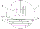
图3为本实用新型图2中A处放大结构示意图;Fig. 3 is the enlarged schematic diagram of the structure at place A in Fig. 2 of the utility model;
图4为本实用新型仰视结构示意图;Fig. 4 is a schematic view of the utility model looking down on the structure;
图5为本实用新型工作结构示意图;Fig. 5 is the working structure schematic diagram of the utility model;
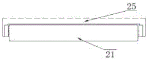
图6为本实用新型压草滚轮与主割草保护罩连接主剖视结构示意图。6 is a schematic cross-sectional view of the main structure of the connection between the grass pressing roller and the main mowing protective cover of the present invention.
图中:1、扶草装置;2、连接拖拉机加固杆;3、变速箱本体;31、传动轴杆;4、变速箱支撑架;5、第一割草皮带轮;6、第一皮带主体;7、第一皮带张紧装置;8、第二皮带主体;9、液压缸;10、第三皮带;11、避障连接装置;12、压力传感装置;13、受力挡杆;14、第二割草皮带轮;15、法兰盘;16、弹力伸缩杆;17、压力传输及支撑杆;18、第三割草皮带轮;19、第二皮带张紧装置;20、输出皮带轮;21、压草滚轮;22、第一刀片;23、第二刀片;24、避障刀片;25、主割草保护罩;26、避障安全罩;27、第一安装轴杆;28、第二安装轴杆;29、拖拉机机架。In the figure: 1. Grass-supporting device; 2. Connecting tractor reinforcement rod; 3. Gearbox body; 31. Transmission shaft; 4. Gearbox support frame; 5. First mowing pulley; 6. First belt body; 7. The first belt tensioning device; 8. The second belt main body; 9. The hydraulic cylinder; 10. The third belt; 11. The obstacle avoidance connecting device; 12. The pressure sensing device; The second mowing pulley; 15, the flange plate; 16, the elastic telescopic rod; 17, the pressure transmission and support rod; 18, the third mowing pulley; 19, the second belt tensioning device; 20, the output pulley; 21, Grass roller; 22, the first blade; 23, the second blade; 24, the obstacle avoidance blade; 25, the main mowing protection cover; 26, the obstacle avoidance safety cover; 27, the first installation shaft; 28, the second installation Axle; 29. Tractor frame.
具体实施方式Detailed ways
下面将结合本实用新型实施例中的附图,对本实用新型实施例中的技术方案进行清楚、完整地描述,显然,所描述的实施例仅仅是本实用新型一部分实施例,而不是全部的实施例。基于本实用新型中的实施例,本领域普通技术人员在没有做出创造性劳动前提下所获得的所有其他实施例,都属于本实用新型保护的范围。The technical solutions in the embodiments of the present utility model will be clearly and completely described below with reference to the accompanying drawings in the embodiments of the present utility model. Obviously, the described embodiments are only a part of the embodiments of the present utility model, rather than all the implementations. example. Based on the embodiments of the present invention, all other embodiments obtained by those of ordinary skill in the art without creative work fall within the protection scope of the present invention.
请参阅图1-6,本实用新型提供一种技术方案:一种立式自动避障除草机,包括扶草装置1、连接拖拉机加固杆2、变速箱本体3、变速箱支撑架4、第一割草皮带轮5、第一皮带主体6、第一皮带张紧装置7、第二皮带主体8、液压缸9、第三皮带10、避障连接装置11、压力传感装置12、受力挡杆13、第二割草皮带轮14、法兰盘15、弹力伸缩杆16、压力传输及支撑杆17、第三割草皮带轮18、第二皮带张紧装置19、输出皮带轮20、压草滚轮21、第一刀片22、第二刀片23、避障刀片24、主割草保护罩25、避障安全罩26、第一安装轴杆27、第二安装轴杆28和拖拉机机架29,扶草装置1的后端与主割草保护罩25相连接,且主割草保护罩25的上方安装有变速箱支撑架4,并且变速箱支撑架4的上方安装有变速箱本体3,变速箱本体3的左右两端焊接有连接拖拉机加固杆2,且变速箱本体3的底端连接有输出皮带轮20,并且输出皮带轮20的外侧连接有第一皮带主体6和第二皮带主体8,第一皮带主体6的下方设置有第二皮带主体8,且第一皮带主体6的左端内部安装有第一割草皮带轮5,并且第一皮带主体6的内部连接有第一皮带张紧装置7,第二皮带主体8的右端内部连接有第三割草皮带轮18,且第三割草皮带轮18的外侧连接有第三皮带10,并且第三皮带10的左端内部连接有第二割草皮带轮14,第二皮带主体8的内部安装有第二皮带张紧装置19,且第二皮带张紧装置19的底端与主割草保护罩25相连接,第二割草皮带轮14的底端与避障连接装置11相连接,且避障连接装置11的左端底端通过法兰盘15与避障安全罩26相连接,并且第二割草皮带轮14的上方安装有压力传输及支撑杆17,压力传输及支撑杆17的左端固定有受力挡杆13,且压力传输及支撑杆17的右端上方安装有压力传感装置12,受力挡杆13的底端通过活动销与弹力伸缩杆16相连接,且弹力伸缩杆16的底端固定有主割草保护罩25,避障连接装置11的后侧面通过活动销与液压缸9相连接,且液压缸9的右端下方固定有主割草保护罩25,避障安全罩26的下方安装有避障刀片24,第二安装轴杆28的底端贯穿主割草保护罩25与第二刀片23相连接,第一安装轴杆27的底端贯穿主割草保护罩25与第一刀片22相连接,且主割草保护罩25的前侧面连接有压草滚轮21,连接拖拉机加固杆2与拖拉机机架29相连接;Please refer to Figures 1-6, the present utility model provides a technical solution: a vertical automatic obstacle avoidance weeder, comprising a grass-supporting
变速箱本体3的内部底端轴承连接有传动轴杆31,且传动轴杆31的底端外侧键连接有输出皮带轮20,并且传动轴杆31的竖向中心线与变速箱本体3的竖向中心线重合,进而便于变速箱本体3通过传动轴杆31将动力传递给输出皮带轮20;The inner bottom end bearing of the
第一割草皮带轮5的横向中心线与第三割草皮带轮18的横向中心线相互平行,且第一割草皮带轮5、第三割草皮带轮18和输出皮带轮20三者的中心连接线构成三角形结构,并且第一割草皮带轮5的最高点高于第三割草皮带轮18的最高点,通过第一割草皮带轮5和第三割草皮带轮18带动两组不同位置的第一刀片22和第二刀片23进行切割工作;The lateral centerline of the first mowing
第一皮带张紧装置7与输出皮带轮20平齐,且第一皮带张紧装置7与第二皮带主体8之间存在间距,以便于第一皮带张紧装置7很好的对输出皮带轮20外侧的第一皮带主体6进行控制和调节;The first
避障连接装置11通过第二安装轴杆28和液压缸9与主割草保护罩25构成旋转结构,且避障连接装置11的旋转角度范围为0-45°,由此使得避障连接装置11很好的带动避障安全罩26进行旋转躲避工作;The obstacle
受力挡杆13呈弧形状结构,且受力挡杆13的弧长大于避障安全罩26周长的二分之一,并且受力挡杆13与压力传输及支撑杆17为一体化结构,以便于通过弧形状结构的受力挡杆13很好的对避障安全罩26进行保护,同时通过弧形状结构设计的受力挡杆13还能减少与障碍物的接触面积;The
压草滚轮21的最高点高于主割草保护罩25,且主割草保护罩25的最前端与拖拉机连接方向向前有2-3m的悬空,并且压草滚轮21的长度与主割草保护罩25前端水平长度相当,由此使得压草滚轮21很好的将草压低,便于第一刀片22和第二刀片23进行除草工作;The highest point of the mowing
第一刀片22的横向中心线与第二刀片23的横向中心线不在同一直线上,且第一刀片22和第二刀片23的材质相同,以便于交错设置的第一刀片22和第二刀片23对不同区域的草进行除去;The transverse centerline of the
避障安全罩26呈圆形状结构,且避障安全罩26通过避障连接装置11与主割草保护罩25构成旋转结构,通过避障安全罩26的旋转便于对避障刀片24进行保护。The obstacle
本实施例的工作原理:在使用该立式自动避障除草机时,首先,如附图5所示,将变速箱本体3左右两侧的连接拖拉机加固杆2通过压箍紧固在拖拉机机架29上,使得如附图2-3所示中的变速箱本体3里面的齿轮与拖拉机机架29上的齿轮相啮合连接,此部分为市场上现有的成熟技术,本申请人在此不作详细的介绍,从而使得整个除草机如附图5所示很好的与遥控式履带拖拉机进行安装固定,便于后期遥控式履带拖拉机带动整个除草机进行移动和传输动力源,然后,启动遥控式履带拖拉机,遥控式履带拖拉机通过内部的齿轮与变速箱本体3内部的齿轮进行啮合旋转,如附图3所示,使得传动轴杆31进行旋转,传动轴杆31将动力传输给下端外侧的输出皮带轮20,输出皮带轮20便开始进行旋转工作了;The working principle of the present embodiment: when using the vertical automatic obstacle avoidance weeder, first, as shown in FIG. On the
接着,如附图2、附图4和附图6所示,整个除草机在行驶的过程中通过压草滚轮21将杂草压低,然后,如附图1-3所示,输出皮带轮20在旋转时将动力传输给外侧的第一皮带主体6和第二皮带主体8,使得输出皮带轮20外侧的第一皮带主体6和第二皮带主体8一同进行旋转,然后,如附图1所示,第一皮带主体6在旋转时将动力传递给第一割草皮带轮5,同时通过第一皮带张紧装置7对第一皮带主体6进行张紧工作,以便于第一皮带主体6很好的进行工作,第一割草皮带轮5在旋转时将动力传递给内部的第一安装轴杆27,由此如图4所示,第一安装轴杆27在旋转时带动底端固定连接的第一刀片22进行旋转割压低的杂草,同理,第二皮带主体8在旋转时带动第三割草皮带轮18进行旋转,使得第三割草皮带轮18在旋转时带动内部的第二安装轴杆28进行旋转,然后,如附图4所示,第二安装轴杆28在旋转时带动底端外侧固定的第二刀片23进行旋转割压低的杂草;Next, as shown in Fig. 2, Fig. 4 and Fig. 6, the weeds are pressed down by the weeding
同时,如附图1所示,第三割草皮带轮18在旋转的过程中将动力传递给第三皮带10,第三皮带10将动力传递给第二割草皮带轮14,使得第二割草皮带轮14通过内部的轴将动力传递给避障刀片24,如附图4所示,使得避障刀片24进行旋转割压低的杂草,当遇到障碍物时,如附图1所示,受力挡杆13受到障碍物的压力,通过压力传输及支撑杆17传输到压力传感装置12上,压力传感装置12将将信息反馈到拖拉机液压阀门控制器上,实现控制液压缸9伸缩,拉着避障连接装置11以第三割草皮带轮18的圆心为定点旋转,实现自动避开障碍物,同时在避开的过程中,避障刀片24保持切割工作,因此便于避障刀片24对较为接近胶树部分的杂草进行除草工作,不需要后期人工的操作,简单,快捷,从而完成一系列工作。Meanwhile, as shown in FIG. 1, the third mowing
尽管参照前述实施例对本实用新型进行了详细的说明,对于本领域的技术人员来说,其依然可以对前述各实施例所记载的技术方案进行修改,或者对其中部分技术特征进行等同替换,凡在本实用新型的精神和原则之内,所作的任何修改、等同替换、改进等,均应包含在本实用新型的保护范围之内。Although the present invention has been described in detail with reference to the foregoing embodiments, for those skilled in the art, it is still possible to modify the technical solutions described in the foregoing embodiments, or perform equivalent replacements for some of the technical features. Within the spirit and principle of the present utility model, any modifications, equivalent replacements, improvements, etc. made shall be included within the protection scope of the present utility model.
Claims (9)
Priority Applications (1)
| Application Number | Priority Date | Filing Date | Title |
|---|---|---|---|
| CN201922021936.3U CN210987053U (en) | 2019-11-21 | 2019-11-21 | Vertical automatic obstacle-avoiding weeding machine |
Applications Claiming Priority (1)
| Application Number | Priority Date | Filing Date | Title |
|---|---|---|---|
| CN201922021936.3U CN210987053U (en) | 2019-11-21 | 2019-11-21 | Vertical automatic obstacle-avoiding weeding machine |
Publications (1)
| Publication Number | Publication Date |
|---|---|
| CN210987053U true CN210987053U (en) | 2020-07-14 |
Family
ID=71466591
Family Applications (1)
| Application Number | Title | Priority Date | Filing Date |
|---|---|---|---|
| CN201922021936.3U Withdrawn - After Issue CN210987053U (en) | 2019-11-21 | 2019-11-21 | Vertical automatic obstacle-avoiding weeding machine |
Country Status (1)
| Country | Link |
|---|---|
| CN (1) | CN210987053U (en) |
Cited By (1)
| Publication number | Priority date | Publication date | Assignee | Title |
|---|---|---|---|---|
| CN110651589A (en) * | 2019-11-21 | 2020-01-07 | 中国热带农业科学院农业机械研究所 | Vertical automatic obstacle-avoiding weeding machine |
-
2019
- 2019-11-21 CN CN201922021936.3U patent/CN210987053U/en not_active Withdrawn - After Issue
Cited By (2)
| Publication number | Priority date | Publication date | Assignee | Title |
|---|---|---|---|---|
| CN110651589A (en) * | 2019-11-21 | 2020-01-07 | 中国热带农业科学院农业机械研究所 | Vertical automatic obstacle-avoiding weeding machine |
| CN110651589B (en) * | 2019-11-21 | 2025-07-01 | 中国热带农业科学院农业机械研究所 | Vertical automatic obstacle avoidance weeder |
Similar Documents
| Publication | Publication Date | Title |
|---|---|---|
| CN110651589A (en) | Vertical automatic obstacle-avoiding weeding machine | |
| CN106961914A (en) | A kind of three disc type orchard avoidance mowing-apparatus | |
| CN109906688B (en) | Film rolling and linkage film unloading device | |
| CN103718679B (en) | Depth self-adjusting type corn inter-row weeding machine | |
| CN110291857A (en) | A paddy field intertillage weeder | |
| CN206713412U (en) | Orchard avoidance hay mover | |
| CN109168343B (en) | Universal inter-plant weeding and scarifier for mulberry and orchards | |
| CN109220013A (en) | A kind of agriculture loosenning tiller with weeding function | |
| CN109906689B (en) | Residual film recycling machine | |
| CN111149502A (en) | Cassava stem separating device of cassava combine harvester | |
| CN208821167U (en) | Combined working machine for soil preparation and residual film recovery | |
| CN202232133U (en) | Pit digging and fertilizing device for fruit gardens | |
| CN206776061U (en) | A kind of three disc type orchard avoidance mowing-apparatus | |
| CN209017403U (en) | A weeding robot for orchard weeding | |
| CN203251627U (en) | Multifunctional harvester | |
| CN105612906A (en) | Interactive garden lawn mower | |
| CN205371347U (en) | Wide angle drive axle | |
| CN204425911U (en) | A kind of rotovator clearing up roadside weeds | |
| CN203884148U (en) | High-speed and efficient paddy field harrow | |
| CN218218214U (en) | Soil turning device for farmland soil restoration | |
| CN203872510U (en) | Rotary cultivator | |
| CN204377422U (en) | A kind of double-disk mower | |
| CN203675552U (en) | Depth self-adjustment-type corn inter-row weeder | |
| CN211240851U (en) | A antiwind high-efficient weed-removing wheel for rural area supervisor | |
| CN206237745U (en) | Cotton field in the ranks self-propelled incomplete film-recovering machine |
Legal Events
| Date | Code | Title | Description |
|---|---|---|---|
| GR01 | Patent grant | ||
| GR01 | Patent grant | ||
| AV01 | Patent right actively abandoned |
Granted publication date: 20200714 Effective date of abandoning: 20250701 |
|
| AV01 | Patent right actively abandoned |
Granted publication date: 20200714 Effective date of abandoning: 20250701 |
|
| AV01 | Patent right actively abandoned | ||
| AV01 | Patent right actively abandoned |