CN210983395U - Anti-falling data acquisition unit - Google Patents
Anti-falling data acquisition unit Download PDFInfo
- Publication number
- CN210983395U CN210983395U CN201922266555.1U CN201922266555U CN210983395U CN 210983395 U CN210983395 U CN 210983395U CN 201922266555 U CN201922266555 U CN 201922266555U CN 210983395 U CN210983395 U CN 210983395U
- Authority
- CN
- China
- Prior art keywords
- plate
- data collector
- fixed
- main body
- rod
- Prior art date
- Legal status (The legal status is an assumption and is not a legal conclusion. Google has not performed a legal analysis and makes no representation as to the accuracy of the status listed.)
- Active
Links
- 230000007246 mechanism Effects 0.000 claims abstract description 35
- 238000003780 insertion Methods 0.000 claims description 16
- 230000037431 insertion Effects 0.000 claims description 16
- 238000010586 diagram Methods 0.000 description 2
- 241001391944 Commicarpus scandens Species 0.000 description 1
- 230000009286 beneficial effect Effects 0.000 description 1
- 230000005540 biological transmission Effects 0.000 description 1
- 238000000034 method Methods 0.000 description 1
- 238000012986 modification Methods 0.000 description 1
- 230000004048 modification Effects 0.000 description 1
Images


Landscapes
- Earth Drilling (AREA)
Abstract
本实用新型涉及防摔技术领域,尤其是一种防摔式数据采集器,包括数据采集器主体和底板,所述数据采集器主体上方两侧均放置有上杆,且上杆通过滑动机构与数据采集器主体相连接,所述底板上方设置有上板,且上板放置在数据采集器主体底部,所述底板上方与上板底部之间连接有多个伸缩机构,所述数据采集器主体两侧均设置有挡板,所述挡板两侧与底板和上杆之间连接有多个缓冲机构。该数据采集器摔落时,通过两侧的挡板便能够对数据采集器主体进行保护,通过缓冲机构能够对挡板进行缓冲。
The utility model relates to the technical field of anti-dropping, in particular to an anti-dropping data collector, comprising a data collector main body and a bottom plate, upper rods are placed on both sides above the data collector main body, and the upper rods are connected with each other through a sliding mechanism. The main body of the data collector is connected to each other, an upper plate is arranged above the bottom plate, and the upper plate is placed at the bottom of the main body of the data collector, and a plurality of telescopic mechanisms are connected between the top of the bottom plate and the bottom of the upper plate, and the main body of the data collector is connected with each other. Baffles are arranged on both sides, and a plurality of buffer mechanisms are connected between the two sides of the baffle, the bottom plate and the upper rod. When the data collector falls, the main body of the data collector can be protected by the baffles on both sides, and the baffles can be buffered by the buffer mechanism.
Description
技术领域technical field
本实用新型涉及防摔技术领域,尤其涉及一种防摔式数据采集器。The utility model relates to the technical field of anti-fall, in particular to an anti-fall data collector.
背景技术Background technique
数据采集器又称盘点机、掌上电脑。它是将条码扫描装置与数据终端一体化,带有电池可离线操作的终端电脑设备。具备实时采集、自动存储、即时显示、即时反馈、自动处理、自动传输功能。为现场数据的真实性、有效性、实时性、可用性提供了保证。现有的数据采集器本身比较脆,如果从高度掉落容易摔坏,为此我们提出了一种防摔式的数据采集器。Data collectors are also called inventory machines and handheld computers. It is a terminal computer equipment that integrates a barcode scanning device and a data terminal, and has a battery that can be operated offline. With real-time acquisition, automatic storage, instant display, instant feedback, automatic processing, automatic transmission functions. It provides a guarantee for the authenticity, validity, real-time and availability of the field data. The existing data collector itself is relatively brittle, and it is easy to break if dropped from a height. For this reason, we propose a drop-proof data collector.
实用新型内容Utility model content
本实用新型的目的是为了解决现有技术中存在容易摔坏的缺点,而提出的一种防摔式数据采集器。The purpose of the utility model is to solve the disadvantage of being easily broken in the prior art, and proposes a drop-proof data collector.
为了实现上述目的,本实用新型采用了如下技术方案:In order to achieve the above-mentioned purpose, the utility model adopts the following technical solutions:
设计一种防摔式数据采集器,包括数据采集器主体和底板,所述数据采集器主体上方两侧均放置有上杆,且上杆通过滑动机构与数据采集器主体相连接,所述底板上方设置有上板,且上板放置在数据采集器主体底部,所述底板上方与上板底部之间连接有多个伸缩机构,所述数据采集器主体两侧均设置有挡板,所述挡板两侧与底板和上杆之间连接有多个缓冲机构,所述缓冲机构包括凹槽和插杆,所述凹槽开设在挡板两侧,所述插杆固定在底板和上杆一侧,所述插杆一端穿过挡板并插设在凹槽内,且插杆一端固定有限位板,所述插杆外套设有弹簧,所述弹簧一端固定在插杆上,所述弹簧另一端固定在挡板上。A drop-proof data collector is designed, including a data collector main body and a bottom plate, upper rods are placed on both sides above the data collector main body, and the upper rod is connected with the data collector main body through a sliding mechanism, the bottom plate An upper plate is arranged above, and the upper plate is placed at the bottom of the main body of the data collector, a plurality of telescopic mechanisms are connected between the top of the bottom plate and the bottom of the upper plate, baffle plates are arranged on both sides of the main body of the data collector, and the A plurality of buffer mechanisms are connected between the two sides of the baffle, the bottom plate and the upper rod. The buffer mechanism includes a groove and an insertion rod. The groove is opened on both sides of the baffle, and the insertion rod is fixed on the bottom plate and the upper rod. On one side, one end of the insertion rod passes through the baffle plate and is inserted into the groove, and one end of the insertion rod is fixed with a limit plate, the outer sleeve of the insertion rod is provided with a spring, and one end of the spring is fixed on the insertion rod, the The other end of the spring is fixed on the baffle.
优选的,所述滑动机构包括滑板和滑槽,所述滑槽开设在数据采集器主体上方两侧,所述滑板固定在上杆底部,且滑板滑动设置在滑槽内,所述滑槽两侧壁与滑板两侧之间连接有卡设机构。Preferably, the sliding mechanism includes a sliding plate and a sliding groove, the sliding grooves are provided on both sides above the main body of the data collector, the sliding plate is fixed on the bottom of the upper rod, and the sliding plate is slidably arranged in the sliding groove, and the sliding groove is two sides of the sliding groove. A clamping mechanism is connected between the side wall and both sides of the slide plate.
优选的,所述卡设机构包括橡胶凸起和弧形凹槽,所述弧形凹槽开设在滑槽两侧壁,所述橡胶凸起固定在滑板两侧,且橡胶凸起能够插设在弧形凹槽内。Preferably, the clamping mechanism includes a rubber protrusion and an arc-shaped groove, the arc-shaped groove is opened on both side walls of the chute, the rubber protrusion is fixed on both sides of the slide plate, and the rubber protrusion can be inserted in the arc groove.
优选的,所述上板上方固定有橡胶垫。Preferably, a rubber pad is fixed above the upper plate.
优选的,所述伸缩机构包括套管和下杆,所述套管镶嵌在底板上方,所述下杆固定在上板底部,所述下杆一端插设在套管内且固定有下限位板,所述下限位板底部固定有下弹簧,所述下弹簧一端固定在套管底部。Preferably, the telescopic mechanism includes a sleeve and a lower rod, the sleeve is embedded above the bottom plate, the lower rod is fixed on the bottom of the upper plate, and one end of the lower rod is inserted into the sleeve and fixed with a lower limit plate, A lower spring is fixed at the bottom of the lower limit plate, and one end of the lower spring is fixed at the bottom of the sleeve.
本实用新型提出的一种防摔式数据采集器,有益效果在于:该数据采集器摔落时,通过两侧的挡板便能够对数据采集器主体进行保护,通过缓冲机构能够对挡板进行缓冲,通过底板能够对数据采集器主体底部进行保护,通过伸缩机构能够对底板进行缓冲,需要对保护装置进行拆卸时,只需要将滑板顺着滑槽滑出即可。The drop-proof data collector proposed by the utility model has the beneficial effects that: when the data collector falls, the main body of the data collector can be protected by the baffles on both sides, and the baffles can be protected by the buffer mechanism. Buffer, the bottom of the main body of the data collector can be protected by the bottom plate, and the bottom plate can be buffered by the telescopic mechanism. When the protection device needs to be disassembled, it is only necessary to slide the slide plate out along the chute.
附图说明Description of drawings
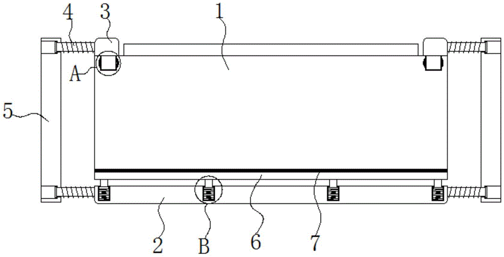
图1为本实用新型提出的一种防摔式数据采集器的主视结构示意图。FIG. 1 is a schematic front view of the structure of a drop-proof data collector proposed by the present invention.
图2为本实用新型提出的一种防摔式数据采集器的俯视结构示意图。FIG. 2 is a top-view structural schematic diagram of a drop-proof data collector proposed by the present invention.
图3为本实用新型提出的一种防摔式数据采集器的缓冲机构结构示意图。3 is a schematic structural diagram of a buffer mechanism of a drop-proof data collector proposed by the present invention.
图4为本实用新型提出的一种防摔式数据采集器的A部结构放大示意图。FIG. 4 is an enlarged schematic view of the structure of part A of a drop-resistant data collector proposed by the present invention.
图5为本实用新型提出的一种防摔式数据采集器的B部结构放大示意图。FIG. 5 is an enlarged schematic view of the structure of part B of a drop-proof data collector proposed by the present invention.
图中:数据采集器主体1、底板2、上杆3、缓存机构4、插杆41、凹槽42、限位板43、弹簧44、挡板5、上板6、橡胶垫7、套管8、下弹簧9、下杆10、下限位板11、滑板12、滑槽13、橡胶凸起14、弧形凹槽15。In the figure: data collector
具体实施方式Detailed ways
下面将结合本实用新型实施例中的附图,对本实用新型实施例中的技术方案进行清楚、完整地描述,显然,所描述的实施例仅仅是本实用新型一部分实施例,而不是全部的实施例。The technical solutions in the embodiments of the present utility model will be clearly and completely described below with reference to the accompanying drawings in the embodiments of the present utility model. Obviously, the described embodiments are only a part of the embodiments of the present utility model, rather than all the implementations. example.
实施例1Example 1
参照图1-3,一种防摔式数据采集器,包括数据采集器主体1和底板2,数据采集器主体1上方两侧均放置有上杆3,且上杆3通过滑动机构与数据采集器主体1相连接,底板2上方设置有上板6,且上板6放置在数据采集器主体1底部,上板6上方固定有橡胶垫7,底板2上方与上板6底部之间连接有多个伸缩机构,数据采集器主体1两侧均设置有挡板5,挡板5两侧与底板2和上杆3之间连接有多个缓冲机构4,缓冲机构4包括凹槽42和插杆41,凹槽42开设在挡板5两侧,插杆41固定在底板2和上杆3一侧,插杆41一端穿过挡板5并插设在凹槽42内,且插杆41一端固定有限位板43,插杆41外套设有弹簧44,弹簧44一端固定在插杆41上,弹簧44另一端固定在挡板5上,当数据采集器主体1摔落时,通过两侧的挡板5便能够对数据采集器主体1进行保护,通过缓冲机构4能够对挡板5进行缓冲,通过底板2能够对数据采集器主体1底部进行保护,通过伸缩机构能够对底板2进行缓冲。1-3, an anti-drop data collector includes a data collector
实施例2Example 2
参照图4,作为本实用新型的另一优选实施例,与实施例1的区别在于,滑动机构包括滑板12和滑槽13,滑槽13开设在数据采集器主体1上方两侧,滑板12固定在上杆3底部,且滑板12滑动设置在滑槽13内,滑槽13两侧壁与滑板12两侧之间连接有卡设机构,卡设机构包括橡胶凸起14和弧形凹槽15,弧形凹槽15开设在滑槽13两侧壁,橡胶凸起14固定在滑板12两侧,且橡胶凸起14能够插设在弧形凹槽15内,通过卡设机构能够对滑板12进行限位,需要将橡胶凸起14移出弧形凹槽15时,只需要用力的拉动滑板12即可,需要对挡板5进行拆卸时,只需要将滑板12顺着滑槽13滑出即可。Referring to FIG. 4 , as another preferred embodiment of the present invention, the difference from
实施例3Example 3
参照图5,作为本实用新型的另一优选实施例,与实施例1的区别在于,伸缩机构包括套管8和下杆10,套管8镶嵌在底板2上方,下杆10固定在上板6 底部,下杆10一端插设在套管8内且固定有下限位板11,下限位板11底部固定有下弹簧9,下弹簧9一端固定在套管8底部,通过下杆10在套管8内移动,再通过下弹簧9便能够对底板2进行缓冲。5 , as another preferred embodiment of the present invention, the difference from
以上所述,仅为本实用新型较佳的具体实施方式,但本实用新型的保护范围并不局限于此,任何熟悉本技术领域的技术人员在本实用新型揭露的技术范围内,根据本实用新型的技术方案及其实用新型构思加以等同替换或改变,都应涵盖在本实用新型的保护范围之内。The above description is only a preferred embodiment of the present invention, but the protection scope of the present invention is not limited to this. Equivalent replacement or modification of the new technical solution and its utility model concept shall be included within the protection scope of the present utility model.
Claims (5)
Priority Applications (1)
| Application Number | Priority Date | Filing Date | Title |
|---|---|---|---|
| CN201922266555.1U CN210983395U (en) | 2019-12-17 | 2019-12-17 | Anti-falling data acquisition unit |
Applications Claiming Priority (1)
| Application Number | Priority Date | Filing Date | Title |
|---|---|---|---|
| CN201922266555.1U CN210983395U (en) | 2019-12-17 | 2019-12-17 | Anti-falling data acquisition unit |
Publications (1)
| Publication Number | Publication Date |
|---|---|
| CN210983395U true CN210983395U (en) | 2020-07-10 |
Family
ID=71421426
Family Applications (1)
| Application Number | Title | Priority Date | Filing Date |
|---|---|---|---|
| CN201922266555.1U Active CN210983395U (en) | 2019-12-17 | 2019-12-17 | Anti-falling data acquisition unit |
Country Status (1)
| Country | Link |
|---|---|
| CN (1) | CN210983395U (en) |
Cited By (1)
| Publication number | Priority date | Publication date | Assignee | Title |
|---|---|---|---|---|
| CN114136014A (en) * | 2021-11-29 | 2022-03-04 | 广东电网有限责任公司 | Solar energy collector |
-
2019
- 2019-12-17 CN CN201922266555.1U patent/CN210983395U/en active Active
Cited By (2)
| Publication number | Priority date | Publication date | Assignee | Title |
|---|---|---|---|---|
| CN114136014A (en) * | 2021-11-29 | 2022-03-04 | 广东电网有限责任公司 | Solar energy collector |
| CN114136014B (en) * | 2021-11-29 | 2025-02-25 | 广东电网有限责任公司 | A solar energy collector |
Similar Documents
| Publication | Publication Date | Title |
|---|---|---|
| CN212659605U (en) | Storage battery convenient to fix and disassemble | |
| CN209949097U (en) | Portable mobile communication equipment | |
| CN210008061U (en) | cabinet frame with adjusting capability | |
| CN204502325U (en) | A kind of table tennis balls collecting ball picking device | |
| CN217544350U (en) | A stacking tool for distribution transformer cores | |
| CN216293418U (en) | File cabinet with clamping and fixing mechanism | |
| CN208337562U (en) | A kind of reliability and durability intercom | |
| CN209930317U (en) | Cam-type spout gravity support | |
| CN210677498U (en) | Novel welding robot | |
| CN219463453U (en) | A portable collection tube | |
| CN210469447U (en) | Storage case for network telephone | |
| CN217806619U (en) | Waste recovery device for electrolytic copper foil production | |
| CN115246531A (en) | A transport preservation system for the detection of RNA methylation in peripheral blood | |
| CN220656166U (en) | Chest outer tube bundle collator | |
| CN110762374A (en) | A smart phone with anti-hands-off function | |
| CN207818800U (en) | A kind of soft package lithium battery steady type mounting structures | |
| CN217173146U (en) | Adjustable material tray lifting component | |
| CN216288759U (en) | A new type of lithium battery protection board placement rack | |
| CN209641639U (en) | A plug-in LED bracket feeding mechanism | |
| CN217878914U (en) | Volcanic ash product formaldehyde detection device | |
| CN213801057U (en) | Prevent biological kit that reagent pipe emptys | |
| CN216269352U (en) | Transfer device for beer production | |
| CN215642506U (en) | Investment model for big data analysis risk for asset management | |
| CN208002417U (en) | A kind of human resource management device | |
| CN209544187U (en) | A kind of remote control device |
Legal Events
| Date | Code | Title | Description |
|---|---|---|---|
| GR01 | Patent grant | ||
| GR01 | Patent grant |