CN210979468U - Arrange with burnishing device convenient to angle is shone in regulation - Google Patents
Arrange with burnishing device convenient to angle is shone in regulation Download PDFInfo
- Publication number
- CN210979468U CN210979468U CN201921980100.XU CN201921980100U CN210979468U CN 210979468 U CN210979468 U CN 210979468U CN 201921980100 U CN201921980100 U CN 201921980100U CN 210979468 U CN210979468 U CN 210979468U
- Authority
- CN
- China
- Prior art keywords
- welded
- motor box
- close
- rack
- gear
- Prior art date
- Legal status (The legal status is an assumption and is not a legal conclusion. Google has not performed a legal analysis and makes no representation as to the accuracy of the status listed.)
- Expired - Fee Related
Links
Images


Landscapes
- Non-Portable Lighting Devices Or Systems Thereof (AREA)
Abstract
本实用新型公开了一种便于调节照射角度的布置用打光装置,涉及灯具技术领域。该便于调节照射角度的布置用打光装置,包括保护壳,保护壳内表壁靠近一侧边缘处焊接有第一齿条,保护壳内表壁沿竖直方向焊接有第二齿条,保护壳底部靠近两侧边缘处均焊接有连接条,两个连接条一侧外表面之间焊接有支撑轨,支撑轨顶部开设有环状凹槽。该便于调节照射角度的布置用打光装置,使用时,通过固定块将设备固定安装后即可操控使用,可控制第一电机盒内电机带动第一齿轮,使装置能够进行水平方向旋转照射,可控制第二电机盒内电机带动第二齿轮,使装置能够进行竖直方向的旋转照射。
The utility model discloses an arrangement lighting device which is convenient for adjusting the irradiation angle, and relates to the technical field of lamps. The lighting device for arrangement, which is convenient for adjusting the irradiation angle, comprises a protective shell, a first rack is welded on the inner surface wall of the protective shell near one side edge, and a second rack is welded on the inner surface wall of the protective shell along the vertical direction to protect the protective shell. Connecting strips are welded at the bottom of the shell near the edges of both sides, support rails are welded between the outer surfaces of one side of the two connecting strips, and an annular groove is provided on the top of the support rails. The lighting device for arrangement, which is easy to adjust the irradiation angle, can be manipulated and used after the device is fixedly installed through the fixing block, and the motor in the first motor box can be controlled to drive the first gear, so that the device can rotate and illuminate in the horizontal direction. The motor in the second motor box can be controlled to drive the second gear, so that the device can rotate and irradiate in the vertical direction.
Description
技术领域technical field
本实用新型涉及灯具技术领域,具体为一种便于调节照射角度的布置用打光装置。The utility model relates to the technical field of lamps, in particular to an arrangement lighting device which is convenient for adjusting the illumination angle.
背景技术Background technique
布置用打光装置是一种能够显示环境的同时渲染气氛,突出中心人物和事物的装置,但是,现有技术中照射角度可调的打光装置内部设计复杂,使设备使用费用较高,仅适合少数场合使用,同时不利于维护,实际使用注意事项较多。The lighting device for layout is a device that can display the environment while rendering the atmosphere, and highlight the central characters and things. However, the internal design of the lighting device with adjustable illumination angle in the prior art is complicated, which makes the equipment cost relatively high. It is suitable for use in a few occasions, and at the same time, it is not conducive to maintenance. There are many precautions in actual use.
实用新型内容Utility model content
针对现有技术的不足,本实用新型提供了一种便于调节照射角度的布置用打光装置,使用后,可以满足便于调节照射角度的同时设备结构简单,方便维护,满足各个使用场合,使用方式简单。Aiming at the deficiencies of the prior art, the utility model provides a lighting device for arrangement which is convenient to adjust the irradiation angle. After use, the device can be easily adjusted to the irradiation angle, and at the same time, the device has a simple structure, is easy to maintain, and satisfies various use occasions. Simple.
为实现以上目的,本实用新型通过以下技术方案予以实现:一种便于调节照射角度的布置用打光装置,包括保护壳,所述保护壳内表壁靠近一侧边缘处焊接有第一齿条,所述保护壳内表壁沿竖直方向焊接有第二齿条,所述保护壳底部靠近两侧边缘处均焊接有连接条,两个所述连接条一侧外表面之间焊接有支撑轨,所述支撑轨顶部开设有环状凹槽,且环状凹槽内部滑动嵌设有第一支撑轴,所述支撑轨顶部靠近一侧边缘处焊接有支撑块,所述支撑块一侧外表面焊接有支撑杆,所述支撑杆外表面靠近一端边缘处滑动套设有转向杆。In order to achieve the above purpose, the present utility model is achieved through the following technical solutions: a lighting device for arrangement that is convenient for adjusting the irradiation angle, comprising a protective shell, and the inner surface wall of the protective shell is welded with a first rack near the edge of one side. , the inner surface wall of the protective shell is welded with a second rack along the vertical direction, the bottom of the protective shell is welded with connecting bars near the edges on both sides, and a support is welded between the outer surfaces of the two connecting bars on one side The top of the support rail is provided with an annular groove, and a first support shaft is slidably embedded in the annular groove. A support block is welded on the top of the support rail near one side edge, and one side of the support block is A support rod is welded on the outer surface, and a steering rod is slidably sleeved on the outer surface of the support rod near one end edge.
优选的,所述第一支撑轴一端焊接有第一电机盒,所述第一电机盒顶部滑动贯穿有第一转轴,所述第一转轴外表面靠近一端边缘处套设有第一齿轮,所述第一齿轮与第一齿条啮合。Preferably, one end of the first support shaft is welded with a first motor box, the top of the first motor box slides through a first rotating shaft, and a first gear is sleeved on the outer surface of the first rotating shaft near the edge of one end, so The first gear meshes with the first rack.
优选的,所述第一电机盒一侧外表面焊接有第一连动杆,所述第一连动杆一端延伸至转向球内部,所述转向球外表面靠近上方处滑动贯穿有第二连动杆,所述转向球外表面靠近下方处焊接有第三连动杆。Preferably, a first linkage rod is welded on the outer surface of one side of the first motor box, one end of the first linkage rod extends to the inside of the steering ball, and the outer surface of the steering ball slides through a second linkage near the upper part. A moving rod, and a third linkage rod is welded near the lower part of the outer surface of the steering ball.
优选的,所述第二连动杆一端焊接有第二电机盒,所述第二电机盒一侧外表面与转向杆一端焊接,所述第二电机盒一侧外表面滑动贯穿有第二转轴,所述第二转轴外表面靠近一端边缘处套设有第二齿轮,所述第二齿轮与第二齿条啮合。Preferably, one end of the second linkage rod is welded with a second motor box, the outer surface of one side of the second motor box is welded to one end of the steering rod, and the outer surface of one side of the second motor box slides through a second rotating shaft , a second gear is sleeved on the outer surface of the second rotating shaft near one end edge, and the second gear is meshed with the second rack.
优选的,所述第三连动杆一端焊接有灯罩。Preferably, a lampshade is welded on one end of the third linkage rod.
优选的,所述保护壳外表面靠近上方处焊接有固定块。Preferably, a fixing block is welded near the upper part of the outer surface of the protective shell.
与现有技术相比,本实用新型提供了一种便于调节照射角度的布置用打光装置。具备以下有益效果:Compared with the prior art, the utility model provides an arrangement lighting device which is convenient to adjust the irradiation angle. Has the following beneficial effects:
(1)、该便于调节照射角度的布置用打光装置,使用时,通过固定块将设备固定安装后即可操控使用,可控制第一电机盒内电机带动第一齿轮,使装置能够进行水平方向旋转照射,可控制第二电机盒内电机带动第二齿轮,使装置能够进行竖直方向的旋转照射。(1) The lighting device for arrangement, which is easy to adjust the irradiation angle, can be manipulated and used after the device is fixed and installed through the fixing block, and the motor in the first motor box can be controlled to drive the first gear, so that the device can be leveled. Directional rotation irradiation can control the motor in the second motor box to drive the second gear, so that the device can perform vertical rotation irradiation.
(2)、该便于调节照射角度的布置用打光装置,使用时,将所需灯管安装至灯罩内,通过保护壳顶部固定块将设备安装固定,控制第一电机盒通过第一转轴带动第一齿轮通过第一齿条和第一支撑轴沿支撑轨进行圆周运动,控制灯光可沿水平方向进行圆周式旋转照射,控制第二电机盒通过第二转轴带动第二齿轮通过第二齿条和转向杆沿竖直方向进行半圆周运动,控制灯光可以沿竖直方向进行半圆周式旋转照射,第一电机盒和第二电机盒配合使用使灯光能够实现半球面区域内进行照射。(2) The lighting device for the arrangement, which is easy to adjust the irradiation angle, when in use, install the required lamp tube into the lampshade, install and fix the device through the top fixing block of the protective shell, and control the first motor box to drive through the first shaft. The first gear moves in a circular motion along the support rail through the first rack and the first support shaft, the control light can be rotated and illuminated circularly in the horizontal direction, and the second motor box is controlled to drive the second gear through the second rack through the second shaft The semi-circular movement with the steering rod in the vertical direction, and the control light can be rotated in a semi-circular direction in the vertical direction.
附图说明Description of drawings
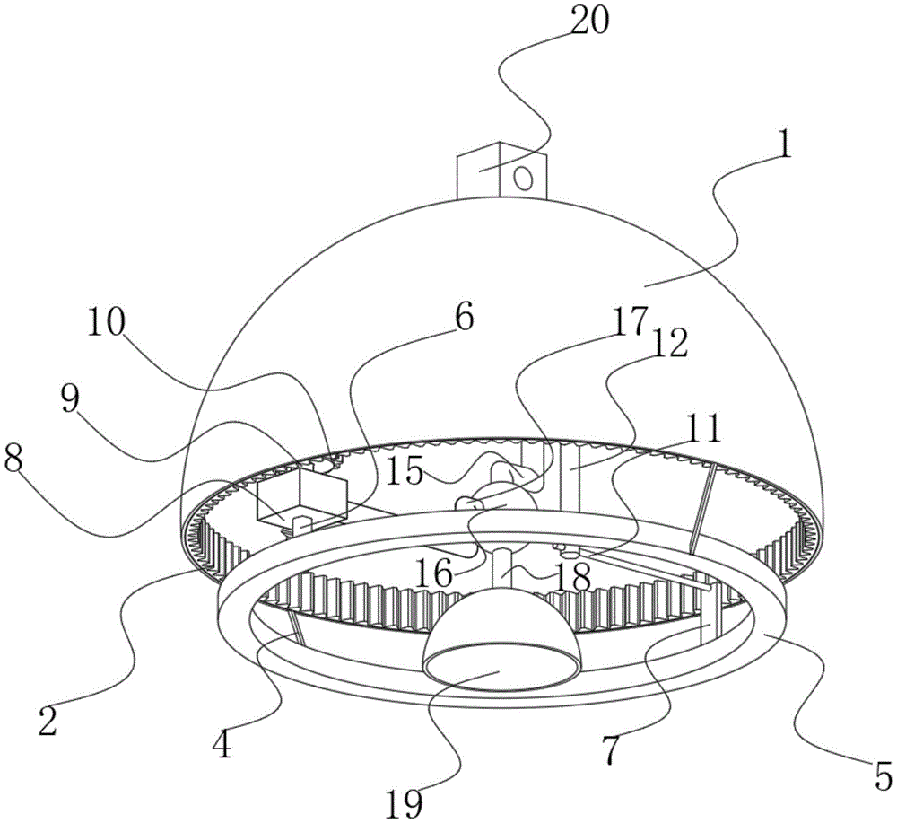
图1为本实用新型的正视立体图;Fig. 1 is the front perspective view of the utility model;
图2为本实用新型的仰视立体图;Fig. 2 is the bottom perspective view of the utility model;
图3为本实用新型的后视剖视立体图;Figure 3 is a rear cross-sectional perspective view of the utility model;
图4为本实用新型的正视剖视立体图;Fig. 4 is the front sectional perspective view of the utility model;
图5为本实用新型的左视剖视立体图。5 is a left cross-sectional perspective view of the utility model.
图中:1、保护壳;2、第一齿条;3、第二齿条;4、连接条;5、支撑轨;6、第一支撑轴;7、支撑块;8、第一电机盒;9、第一转轴;10、第一齿轮;11、支撑杆;12、转向杆;13、第二电机盒;14、第二齿轮;15、第二连动杆;16、转向球;17、第一连动杆;18、第三连动杆;19、灯罩;20、固定块;21、第二转轴。In the figure: 1, protective shell; 2, first rack; 3, second rack; 4, connecting bar; 5, support rail; 6, first support shaft; 7, support block; 8, first motor box ; 9, the first shaft; 10, the first gear; 11, the support rod; 12, the steering rod; 13, the second motor box; 14, the second gear; 15, the second link rod; 16, the steering ball; 17 , the first linkage rod; 18, the third linkage rod; 19, the lampshade; 20, the fixed block; 21, the second shaft.
具体实施方式Detailed ways
下面将结合本实用新型实施例中的附图,对本实用新型提供一种技术方案进行、完整地描述,显然,所述的实施例仅仅是本实用新型一部分实施例,而不是全部的实施例。In the following, a technical solution provided by the present invention will be fully described with reference to the accompanying drawings in the embodiments of the present invention. Obviously, the described embodiments are only a part of the embodiments of the present invention, not all of the embodiments.
所述实施例的示例在附图中示出,其中自始至终相同或类似的标号表示相同或类似的元件或具有相同或类似功能的元件。下面通过参考附图描述的实施例是示例性的,旨在用于解释本实用新型,而不能理解为对本实用新型的限制。Examples of such embodiments are illustrated in the accompanying drawings, wherein the same or similar reference numerals refer to the same or similar elements or elements having the same or similar functions throughout. The embodiments described below with reference to the accompanying drawings are exemplary, and are intended to be used to explain the present invention, but should not be construed as a limitation of the present invention.
请参阅图1-5,本实用新型提供一种技术方案:一种便于调节照射角度的布置用打光装置,包括保护壳1,保护壳1的设立是为了防止长时间设备内部出现严重落尘情况,影响设备的使用,同时起到保护设备在移动过程中不会轻易受到损坏,保护壳1内表壁靠近一侧边缘处焊接有第一齿条2,第一齿条2的设立是为了实现灯光进行水平方向的角度调节,保护壳1内表壁沿竖直方向焊接有第二齿条3,第二齿条3的设立是为了实现灯光进行竖直方向的角度调节,第一齿条2和第二齿条3的配合使用,使装置能够进行半球区域内进行角度调节,保护壳1底部靠近两侧边缘处均焊接有连接条4,连接条4的设立是为了连接和固定支撑轨5,为设备内部部件提供支撑点,两个连接条4一侧外表面之间焊接有支撑轨5,支撑轨5的设立是为了支撑第一支撑轴6,支撑轨5顶部开设有环状凹槽,环状凹槽的设立是为了固定第一支撑轴6的同时,固定第一支撑轴6的运动方向,且环状凹槽内部滑动嵌设有第一支撑轴6,第一支撑轴6的设立是为了支撑第一电机盒8的同时限制第一电机盒8的运动方向,支撑轨5顶部靠近一侧边缘处焊接有支撑块7,支撑块7的设立是为了提供连接支撑杆11的支撑点,使支撑杆11能够起到支撑转向杆12的作用,支撑块7一侧外表面焊接有支撑杆11,支撑杆11的设立是为了限制转向杆12的转动方向的同时,为转向杆12提供支撑点,支撑杆11外表面靠近一端边缘处滑动套设有转向杆12,转向杆12的设立是为了为第二电机盒13提供支撑点的同时限制第二电机盒13的运动方向。Please refer to FIGS. 1-5, the present utility model provides a technical solution: a lighting device for arrangement that is convenient for adjusting the irradiation angle, including a protective shell 1, and the protective shell 1 is established to prevent serious dust falling inside the equipment for a long time. , affecting the use of the equipment, and at the same time protecting the equipment from being easily damaged during the movement process. The inner surface wall of the protective shell 1 is welded with a
第一支撑轴6一端焊接有第一电机盒8,第一电机盒8的设立是为了提供设备进行水平方向调节打光角度的动力,实现设备的水平角度调节打光角度,第一电机盒8顶部滑动贯穿有第一转轴9,第一转轴9的设立是为了带动第一齿轮10转动实现水平方向调节打光角度,第一转轴9外表面靠近一端边缘处套设有第一齿轮10,第一齿轮10的设立是为了配合第一齿条2实现水平方向的旋转,第一齿轮10与第一齿条2啮合,第一电机盒8一侧外表面焊接有第一连动杆17,第一连动杆17的设立是为了带动转向球16进行水平方向的旋转,进而实现调节水平方向的打光角度,第一连动杆17一端延伸至转向球16内部,转向球16外表面靠近上方处滑动贯穿有第二连动杆15,第二连动杆15的设立是为了控制转向球16在竖直方向的转动,从而进行设备竖直方向打光角度的调节,转向球16外表面靠近下方处焊接有第三连动杆18,第三连动杆18的设立是为了在转向球16的带动下使灯罩19进行相应的角度调节,第二连动杆15一端焊接有第二电机盒13,第二电机盒13的设立是为了提供竖直方向调节角度时提供转动所需的动力,第二电机盒13一侧外表面与转向杆12一端焊接,第二电机盒13一侧外表面滑动贯穿有第二转轴21,第二转轴21的设立是为了带动第二齿轮14进行旋转,实现竖直方向的打光角度的调节,第二转轴21外表面靠近一端边缘处套设有第二齿轮14,第二齿轮14的设立是为了配合第二齿条3进行竖直方向进行半圆周运动,实现水平方向的打光角度的调节,第二齿轮14与第二齿条3啮合,第三连动杆18一端焊接有灯罩19,灯罩19的设立是为了保护内部设置的灯管,同时使光线更加居中,提高照射效果,保护壳1外表面靠近上方处焊接有固定块20,固定块20的设立是为了固定装置。One end of the
在使用设备时,通过固定块20将设备固定安装后即可操控使用,可控制第一电机盒8内电机带动第一齿轮10,使装置能够进行水平方向旋转照射,可控制第二电机盒13内电机带动第二齿轮14,使装置能够进行竖直方向的旋转照射,使用时,将所需灯管安装至灯罩19内,通过保护壳1顶部固定块20将设备安装固定,控制第一电机盒8通过第一转轴9带动第一齿轮10通过第一齿条2和第一支撑轴6沿支撑轨5进行圆周运动,控制灯光可沿水平方向进行圆周式旋转照射,控制第二电机盒13通过第二转轴21带动第二齿轮14通过第二齿条3和转向杆12沿竖直方向进行半圆周运动,控制灯光可以沿竖直方向进行半圆周式旋转照射,第一电机盒8和第二电机盒13配合使用使灯光能够实现半球面区域内进行照射。When using the device, the device can be manipulated and used after being fixed and installed by the fixing
以上,仅为本实用新型较佳的具体实施方式,但本实用新型的保护范围并不局限于此,任何熟悉本技术领域的技术人员在本实用新型揭露的技术范围内,根据本实用新型的技术方案及其实用新型构思加以等同替换或改变,都应涵盖在本实用新型的保护范围之内。The above are only the preferred specific embodiments of the present invention, but the protection scope of the present invention is not limited thereto. Equivalent replacement or modification of the technical solution and its utility model concept shall be included within the protection scope of the present utility model.
Claims (6)
Priority Applications (1)
| Application Number | Priority Date | Filing Date | Title |
|---|---|---|---|
| CN201921980100.XU CN210979468U (en) | 2019-11-16 | 2019-11-16 | Arrange with burnishing device convenient to angle is shone in regulation |
Applications Claiming Priority (1)
| Application Number | Priority Date | Filing Date | Title |
|---|---|---|---|
| CN201921980100.XU CN210979468U (en) | 2019-11-16 | 2019-11-16 | Arrange with burnishing device convenient to angle is shone in regulation |
Publications (1)
| Publication Number | Publication Date |
|---|---|
| CN210979468U true CN210979468U (en) | 2020-07-10 |
Family
ID=71437930
Family Applications (1)
| Application Number | Title | Priority Date | Filing Date |
|---|---|---|---|
| CN201921980100.XU Expired - Fee Related CN210979468U (en) | 2019-11-16 | 2019-11-16 | Arrange with burnishing device convenient to angle is shone in regulation |
Country Status (1)
| Country | Link |
|---|---|
| CN (1) | CN210979468U (en) |
Cited By (7)
| Publication number | Priority date | Publication date | Assignee | Title |
|---|---|---|---|---|
| CN111830666A (en) * | 2020-09-01 | 2020-10-27 | 中建交通建设集团有限公司 | Device for controlling single prism to rotate and construction method thereof |
| CN113217831A (en) * | 2021-07-07 | 2021-08-06 | 深圳市其利顺光电有限公司 | LED packaging structure and LED light source device |
| CN113341631A (en) * | 2021-06-29 | 2021-09-03 | 王凯 | Polishing system and method for live broadcast |
| CN113739043A (en) * | 2021-08-25 | 2021-12-03 | 四川公众项目咨询管理有限公司 | Automatic change electric power construction supervision system |
| CN116372370A (en) * | 2023-04-13 | 2023-07-04 | 宝鸡丰立德制造有限公司 | High-efficient laser welding device |
| CN119713198A (en) * | 2025-02-27 | 2025-03-28 | 浩立机械(烟台)有限公司 | Portable lighting device of embedded building site night construction |
| CN119983166A (en) * | 2025-04-14 | 2025-05-13 | 广东顺德高迅电子股份有限公司 | An intelligent interactive lighting angle control device |
-
2019
- 2019-11-16 CN CN201921980100.XU patent/CN210979468U/en not_active Expired - Fee Related
Cited By (8)
| Publication number | Priority date | Publication date | Assignee | Title |
|---|---|---|---|---|
| CN111830666A (en) * | 2020-09-01 | 2020-10-27 | 中建交通建设集团有限公司 | Device for controlling single prism to rotate and construction method thereof |
| CN113341631A (en) * | 2021-06-29 | 2021-09-03 | 王凯 | Polishing system and method for live broadcast |
| CN113217831A (en) * | 2021-07-07 | 2021-08-06 | 深圳市其利顺光电有限公司 | LED packaging structure and LED light source device |
| CN113739043A (en) * | 2021-08-25 | 2021-12-03 | 四川公众项目咨询管理有限公司 | Automatic change electric power construction supervision system |
| CN116372370A (en) * | 2023-04-13 | 2023-07-04 | 宝鸡丰立德制造有限公司 | High-efficient laser welding device |
| CN116372370B (en) * | 2023-04-13 | 2024-02-09 | 宝鸡丰立德制造有限公司 | High-efficient laser welding device |
| CN119713198A (en) * | 2025-02-27 | 2025-03-28 | 浩立机械(烟台)有限公司 | Portable lighting device of embedded building site night construction |
| CN119983166A (en) * | 2025-04-14 | 2025-05-13 | 广东顺德高迅电子股份有限公司 | An intelligent interactive lighting angle control device |
Similar Documents
| Publication | Publication Date | Title |
|---|---|---|
| CN207999759U (en) | A kind of liftable dual-purpose type solar street light | |
| CN108302487A (en) | Automobile head light distance-light light modulating device | |
| CN207621722U (en) | A floodlight with adjustable angle | |
| CN207584503U (en) | A kind of rotating LED lamp | |
| CN110762453A (en) | Height and illumination angle all adjustable lighting device for engineering | |
| CN211475636U (en) | Adjustable projecting lamp with lamp face protect function | |
| CN221763447U (en) | Angle-adjustable human-living environment artistic illumination simulation device | |
| CN107726137A (en) | A kind of multidirectional regulation Down lamp | |
| CN209294843U (en) | A kind of live lighting device of multi-angle regulation | |
| CN207471310U (en) | A kind of aerial lighting apparatus with holder | |
| CN217540426U (en) | Outdoor angle-adjustable LED projection lamp | |
| CN207893479U (en) | The mounting structure of LED line shape lamp at a kind of arm supports beam | |
| CN215220218U (en) | A combined multifunctional voice advertising screen | |
| CN211029988U (en) | A welding robot with no dead ends | |
| CN210921039U (en) | A floor lighting fixture | |
| CN206386893U (en) | A kind of wirelessly controlled LED Projecting Lamp | |
| CN204191909U (en) | Illumination adjustable study desk | |
| CN207334365U (en) | A kind of indoor design floor lamp | |
| CN216644013U (en) | Projection lamp with adjustable projection angle | |
| CN211289667U (en) | Basketball stand type desk lamp | |
| CN207421906U (en) | A kind of light beam Adjustable head lamp | |
| CN223499470U (en) | A multifunctional jewelry observation lamp | |
| CN218095631U (en) | Museum exhibition track lamp of can zooming adjustable light | |
| CN206973416U (en) | A kind of construction site lighting device | |
| CN217816610U (en) | Spotlight with adjustable lighting fixture |
Legal Events
| Date | Code | Title | Description |
|---|---|---|---|
| GR01 | Patent grant | ||
| GR01 | Patent grant | ||
| CF01 | Termination of patent right due to non-payment of annual fee | ||
| CF01 | Termination of patent right due to non-payment of annual fee |
Granted publication date: 20200710 |