CN210938403U - Negative chamfering machining clamp for cutter - Google Patents

Negative chamfering machining clamp for cutter Download PDF

Info

Publication number
CN210938403U
CN210938403U CN201921916962.6U CN201921916962U CN210938403U CN 210938403 U CN210938403 U CN 210938403U CN 201921916962 U CN201921916962 U CN 201921916962U CN 210938403 U CN210938403 U CN 210938403U
Authority
CN
China
Prior art keywords
rotating shaft
tool
clamping
tool holder
slider
Prior art date
Legal status (The legal status is an assumption and is not a legal conclusion. Google has not performed a legal analysis and makes no representation as to the accuracy of the status listed.)
Expired - Fee Related
Application number
CN201921916962.6U
Other languages
Chinese (zh)
Inventor
李嫚
房祥辉
陈乾
董海
张弘弢
宁刚志
Current Assignee (The listed assignees may be inaccurate. Google has not performed a legal analysis and makes no representation or warranty as to the accuracy of the list.)
Dalian University of Technology
Original Assignee
Dalian University of Technology
Priority date (The priority date is an assumption and is not a legal conclusion. Google has not performed a legal analysis and makes no representation as to the accuracy of the date listed.)
Filing date
Publication date
Application filed by Dalian University of Technology filed Critical Dalian University of Technology
Priority to CN201921916962.6U priority Critical patent/CN210938403U/en
Application granted granted Critical
Publication of CN210938403U publication Critical patent/CN210938403U/en
Expired - Fee Related legal-status Critical Current
Anticipated expiration legal-status Critical

Links

Images

Landscapes

  • Finish Polishing, Edge Sharpening, And Grinding By Specific Grinding Devices (AREA)

Abstract

本实用新型提供一种刀具负倒棱加工夹具,属于机械加工领域。该装置包括位置调节机构、转轴机构和角度调节机构三个部分。负倒棱的加工目前主要依靠国外进口的专用可转位刀具数控精密磨床和专用负倒棱夹具辅助的普通磨床磨削。借助国外专用可转位刀具数控精密磨床磨削的负倒棱精度高质量稳定,但设备投资大;而国内利用专用负倒棱夹具的普通磨床磨削,设备投资少,但磨削的负倒棱精度低质量不稳定,且操作不方便。本实用新型扩大普通磨床的加工范围,使得在普通磨床上能够加工出精度较高质量稳定的负倒棱;同时结构简单,操作方便,提高刀具加工生产效率,降低生产成本。
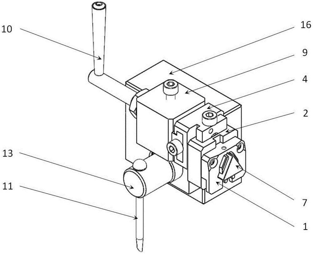
Figure 201921916962

The utility model provides a tool negative chamfering processing fixture, which belongs to the field of mechanical processing. The device includes three parts: a position adjusting mechanism, a rotating shaft mechanism and an angle adjusting mechanism. At present, the processing of negative chamfering mainly relies on the special indexable tool CNC precision grinder imported from abroad and the ordinary grinder assisted by the special negative chamfering fixture. With the help of foreign special indexable tool CNC precision grinder, the precision of negative chamfering is high quality and stable, but the equipment investment is large; while the ordinary grinder grinding using special negative chamfering fixture in China has less equipment investment, but the negative chamfering of grinding. The edge precision is low, the quality is unstable, and the operation is inconvenient. The utility model expands the processing range of the common grinding machine, so that the common grinding machine can process the negative chamfer with high precision and stable quality; meanwhile, the structure is simple, the operation is convenient, the cutting tool processing production efficiency is improved, and the production cost is reduced.

Figure 201921916962

Description

一种刀具负倒棱加工夹具A tool for negative chamfering machining fixture

技术领域technical field

本实用新型属于机械加工领域,具体涉及一种刀具负倒棱加工夹具。The utility model belongs to the field of mechanical processing, in particular to a tool negative chamfering processing fixture.

背景技术Background technique

刀具的负倒棱是在刀具刃口处磨削出的宽度约为0.1~0.2mm的负前角平面,以此增大刀具楔角提高刀具强度,同时改变散热条件,可在强化刀刃又使切削力增加不多的基础上提高刀具的耐用度。在许多硬质合金刀具、陶瓷刀具、PCBN刀具及各种机夹刀片上均采用磨削负倒棱的方式增加刀刃强度。The negative chamfering of the tool is a negative rake angle plane with a width of about 0.1-0.2mm that is ground at the cutting edge of the tool, so as to increase the wedge angle of the tool to improve the strength of the tool, and at the same time change the heat dissipation conditions, which can strengthen the cutting edge. On the basis of not increasing the cutting force, the durability of the tool is improved. On many carbide tools, ceramic tools, PCBN tools and various machine-clamped blades, the method of grinding negative chamfers is used to increase the strength of the cutting edge.

负倒棱的加工目前主要依靠国外进口的专用可转位刀具数控精密磨床和专用负倒棱夹具辅助的普通磨床磨削。由于国外对于精密磨削先进技术存在技术堡垒,一些国外精密数控磨床我们很难一窥究竟;而国内刀具加工工厂自主设计的负倒棱夹具相对简陋所磨削的负倒棱质量较差,操作起来不方便,故为有效方便的加工各种刀具的负倒棱,而又不需借助国外昂贵的刀具精密磨床,我们旨在设计一种刀具负倒棱磨削夹具,扩大普通磨床的加工范围,使我们能够在普通磨床上磨削出质量较高的负倒棱刀具。At present, the processing of negative chamfering mainly relies on the special indexable tool CNC precision grinder imported from abroad and the ordinary grinder assisted by the special negative chamfering fixture. Due to the existence of technological fortresses in advanced precision grinding technology abroad, it is difficult for us to get a glimpse of some foreign precision CNC grinding machines; while the negative chamfering fixtures independently designed by domestic tool processing factories are relatively poor in quality and poor in operation. It is inconvenient to get up, so in order to effectively and conveniently process the negative chamfers of various tools without resorting to foreign expensive tool precision grinders, we aim to design a tool negative chamfer grinding fixture to expand the processing range of ordinary grinders , so that we can grind high-quality negative chamfering tools on ordinary grinding machines.

实用新型内容Utility model content

本实用新型的目的就在于解决上述问题,提供一种新型刀具负倒棱加工夹具。The purpose of the utility model is to solve the above problems and provide a novel tool negative chamfer machining fixture.

本实用新型采用的技术方案如下:The technical scheme adopted by the utility model is as follows:

一种刀具负倒棱加工夹具,包括位置调节机构、转轴机构和角度调节机构。A tool negative chamfering processing fixture comprises a position adjusting mechanism, a rotating shaft mechanism and an angle adjusting mechanism.

所述的位置调节机构包括刀架1、上滑块2、第一丝杠螺栓3、中间滑块4、转轴5、刀具夹块6、刀具7和第二丝杠螺栓8。The position adjustment mechanism includes a tool rest 1 , an upper slider 2 , a first lead screw bolt 3 , an intermediate slider 4 , a rotating shaft 5 , a tool clamping block 6 , a tool 7 and a second lead screw bolt 8 .

所述刀架1前侧面设有用于刀具定位的八字形定位挡板和用于刀架固定螺栓安装的柱形沉头孔;刀架1底部设有一个用于安装刀具夹块6的T形槽,T形槽前端与刀架前侧面相通,T形槽槽向与八字形定位挡板开口方向相对,T形槽顶部设有用于刀具夹块6固定的螺栓孔;刀架1后侧面设有用于刀架安装定位的定位块。所述刀架1需根据所加工的不同刀具型号更换不同的刀架以此满足不同刀具负倒棱磨削的需求。The front side of the tool holder 1 is provided with a figure-eight positioning baffle plate for tool positioning and a cylindrical countersunk hole for the installation of the tool holder fixing bolts; the bottom of the tool holder 1 is provided with a T-shaped for installing the tool holder block 6 . The front end of the T-shaped groove communicates with the front side of the tool holder, the T-shaped groove is opposite to the opening direction of the figure-eight positioning baffle, and the top of the T-shaped groove is provided with a bolt hole for fixing the tool holder 6; the rear side of the tool holder 1 is provided with There is a positioning block for the positioning of the tool holder. The tool holder 1 needs to be replaced with different tool holders according to different tool types to be processed, so as to meet the needs of negative chamfer grinding of different tools.

所述上滑块2为不规则结构,其前侧面设有用于刀架1定位的定位槽和用于刀架1固定的螺栓孔;后部设有一个矩形槽,矩形槽中间设有螺母结构,该螺母结构与第二丝杠螺栓8配合运动可使上滑块2带动刀架1沿Y方向运动;矩形槽侧面设有螺栓孔,安装夹紧螺栓,用于固定上滑块2。The upper slider 2 is an irregular structure, and its front side is provided with a positioning groove for positioning the tool holder 1 and a bolt hole for fixing the tool holder 1; , the nut structure and the second screw bolt 8 can cooperate to move the upper slider 2 to drive the tool holder 1 to move in the Y direction;

所述第一丝杠螺栓3为一内六角螺栓,在其靠近螺栓头位置设一环形半圆槽,用于将第一丝杠螺栓3通过销柱安装于转轴5前端的T形滑块上。The first lead screw bolt 3 is a hexagon socket bolt, and an annular semicircular groove is set near the bolt head for installing the first lead screw bolt 3 on the T-shaped slider at the front end of the rotating shaft 5 through the pin.

所述中间滑块4为不规则结构,其前端设有矩形滑块,矩形滑块可沿上滑块2后侧面的矩形槽滑动,矩形滑块内设有一凹槽,用于安装上滑块2的螺母结构,矩形滑块前侧面设有销孔通过销柱固定安装第二丝杠螺栓8。中间滑块4后端中部设有一矩形槽,前端的矩形滑块与后端的矩形槽空间位置垂直,矩形槽中间同样设有一个螺母结构,该螺母结构与第一丝杠螺栓3的配合运动可使中间滑块4带动上滑块2与刀架1沿X方向运动;矩形槽侧面设有一螺栓孔,用来安装一夹紧螺栓固定转轴5前端T形滑块在矩形槽的位置。The middle slider 4 is an irregular structure, and its front end is provided with a rectangular slider. The rectangular slider can slide along the rectangular groove on the rear side of the upper slider 2. The rectangular slider is provided with a groove for installing the upper slider. The nut structure of 2, the front side of the rectangular slider is provided with a pin hole, and the second lead screw bolt 8 is fixedly installed through the pin column. There is a rectangular slot in the middle of the rear end of the middle slider 4, the rectangular slider at the front end is perpendicular to the rectangular slot at the rear end, and a nut structure is also arranged in the middle of the rectangular slot, and the nut structure and the first screw bolt 3 can cooperate with each other. The middle slider 4 drives the upper slider 2 and the tool holder 1 to move in the X direction; the side of the rectangular groove is provided with a bolt hole for installing a clamping bolt to fix the position of the T-shaped slider at the front end of the rotating shaft 5 in the rectangular groove.

所述刀具夹块6为一T形块,刀具夹块6能够沿刀架1侧面的T形槽滑动,T形块前端设有一凹槽,可以实现四边形刀具的装夹;凹槽两侧棱边设有相应的倒角方便刀具装夹。The tool clamping block 6 is a T-shaped block. The tool clamping block 6 can slide along the T-shaped groove on the side of the tool holder 1. The front end of the T-shaped block is provided with a groove, which can realize the clamping of a quadrilateral tool; The edges are provided with corresponding chamfers to facilitate tool clamping.

所述刀具7通过刀架1前端面的八字形定位挡板进行定位,并通过刀具夹块6和一内六角螺栓固定在刀架1上。The tool 7 is positioned by the figure-eight positioning baffle on the front end surface of the tool holder 1, and is fixed on the tool holder 1 by a tool holder 6 and an inner hexagon bolt.

所述的第二丝杠螺栓8为一内六角螺栓,在其靠近螺栓头位置设一环形半圆槽,用于将第二丝杠螺栓8通过销柱安装于中间滑块4前端面的矩形滑块上。The second lead screw bolt 8 is a hexagon socket head bolt, and an annular semicircular groove is set near the bolt head for mounting the second lead screw bolt 8 on the rectangular slide on the front end surface of the intermediate slider 4 through the pin. on the block.

所述的转轴机构包括转轴5、转轴基座9和摇把10。The rotating shaft mechanism includes a rotating shaft 5 , a rotating shaft base 9 and a crank handle 10 .

所述转轴5前端设有一T形滑块,T形滑块可沿中间滑块4后端的矩形槽滑动;T形滑块中间设有一个凹槽,用于与中间滑块4的螺母结构配合,T形滑块前侧面设有销孔用于安装第一丝杠螺栓3。所述转轴5中部放置在转轴基座9上部水平方向的阶梯通孔内,放置后,转轴5水平方向通过螺母顶紧。所述转轴5后端设有一螺纹通孔用于安装摇把10。The front end of the rotating shaft 5 is provided with a T-shaped sliding block, and the T-shaped sliding block can slide along the rectangular groove at the rear end of the intermediate sliding block 4; , The front side of the T-shaped slider is provided with a pin hole for installing the first screw bolt 3 . The middle part of the rotating shaft 5 is placed in the stepped through hole in the horizontal direction at the upper part of the rotating shaft base 9 , and after being placed, the rotating shaft 5 is pushed tightly by the nut in the horizontal direction. The rear end of the rotating shaft 5 is provided with a threaded through hole for installing the crank handle 10 .

所述转轴基座9为一阶梯矩形块结构,其上部垂直于前侧面方向设有一阶梯通孔,阶梯孔前后两侧直径较大用于安装深沟球轴承,保证转轴5在工作情况下的平稳运转。转轴基座9顶部设有螺纹孔,安装一内六角螺栓用于固定转轴5防止其在调节位置调节机构时转动。转轴基座9底部阶梯台左右侧面设有通孔用于安装夹紧轴13,固定转轴基座9的位置,底部阶梯台后侧面设有两螺纹孔用于安装角度指针14。The rotating shaft base 9 is a stepped rectangular block structure, the upper part of which is perpendicular to the direction of the front side face is provided with a stepped through hole. Smooth operation. The top of the rotating shaft base 9 is provided with a threaded hole, and a hexagon socket head bolt is installed to fix the rotating shaft 5 to prevent it from rotating when adjusting the position adjusting mechanism. There are through holes on the left and right sides of the stepped platform at the bottom of the rotating shaft base 9 for installing the clamping shaft 13 to fix the position of the rotating shaft base 9 .

所述摇把10为设有一阶梯台的锥形圆柱体,端部直径尺寸较小位置处设有螺纹,用于与转轴5相连带动转轴5转动。所述摇把10用于增大转轴5的旋转半径,方便操作员旋转转轴5。The crank handle 10 is a conical cylindrical body with a stepped platform, and a thread is provided at the position where the diameter of the end portion is small, which is used for connecting with the rotating shaft 5 to drive the rotating shaft 5 to rotate. The crank handle 10 is used to increase the rotation radius of the rotating shaft 5 to facilitate the operator to rotate the rotating shaft 5 .

所述转轴5中部贯穿转轴基座9的阶梯通孔,转轴5前端T形滑块后端面通过平垫圈与转轴基座9阶梯孔前侧配合的深沟球轴承接触,平垫圈外径尺寸略小于深沟球轴承外圈的内径尺寸,保证平垫圈与深沟球轴承的内圈相贴合,使得转轴5能随深沟球轴承内圈旋转而旋转。转轴基座9阶梯孔后侧配合的深沟球轴承与一推力球轴承贴合,与同转轴5中部螺纹配合的紧固螺栓共同保证转轴5的固定。The middle part of the rotating shaft 5 penetrates the stepped through hole of the rotating shaft base 9, and the rear end surface of the T-shaped slider at the front end of the rotating shaft 5 is in contact with the deep groove ball bearing matched with the front side of the stepped hole of the rotating shaft base 9 through a flat washer. The outer diameter of the flat washer is slightly larger. It is smaller than the inner diameter of the outer ring of the deep groove ball bearing to ensure that the flat washer fits the inner ring of the deep groove ball bearing, so that the shaft 5 can rotate with the rotation of the inner ring of the deep groove ball bearing. The deep groove ball bearing matched with the rear side of the stepped hole of the rotating shaft base 9 is fitted with a thrust ball bearing, and the fastening bolts threaded with the middle of the rotating shaft 5 jointly ensure the fixing of the rotating shaft 5 .

所述的角度调节机构包括夹紧销11、尼龙套12、夹紧轴13、角度指针14和基座15。The angle adjustment mechanism includes a clamping pin 11 , a nylon sleeve 12 , a clamping shaft 13 , an angle pointer 14 and a base 15 .

所述夹紧轴13为设有两阶梯台的圆柱轴。在其一端直径最小部分设有螺纹,穿过转轴基座9底部阶梯台,将夹紧轴13固定在基座15上;另一端直径最大部分设有一销柱孔,用于安装夹紧销11方便操作员旋转夹紧轴13;中间光轴部分用于与转轴基座9相配合固定转轴基座9的位置。The clamping shaft 13 is a cylindrical shaft with two stepped platforms. The part with the smallest diameter at one end is provided with a thread, which passes through the step platform at the bottom of the rotating shaft base 9 to fix the clamping shaft 13 on the base 15; the part with the largest diameter at the other end is provided with a pin hole for installing the clamping pin 11 It is convenient for the operator to rotate the clamping shaft 13 ; the middle optical shaft part is used to cooperate with the rotating shaft base 9 to fix the position of the rotating shaft base 9 .

所述夹紧销11一端为半球头,半球头直径大于夹紧轴13的销柱孔内径,另一端为椭圆柱,中部为圆柱结构。夹紧销11中部穿过夹紧轴13的销柱孔,半球头与椭圆柱尾部使其能够上下窜动而不脱离夹紧轴13。夹紧销11可使其在本身尺寸较小的情况下方便操作员旋转夹紧轴13。One end of the clamping pin 11 is a hemispherical head, the diameter of the hemispherical head is larger than the inner diameter of the pin hole of the clamping shaft 13 , the other end is an elliptical cylinder, and the middle part is a cylindrical structure. The middle of the clamping pin 11 passes through the pin hole of the clamping shaft 13 , and the hemispherical head and the tail of the elliptical column enable it to move up and down without breaking away from the clamping shaft 13 . The clamping pin 11 can make it convenient for the operator to rotate the clamping shaft 13 under the condition of its own small size.

所述尼龙套12为尼龙材料圆环,安装在夹紧轴13与转轴基座9之间确保夹紧时不损伤两零件表面。The nylon sleeve 12 is a nylon material ring, which is installed between the clamping shaft 13 and the rotating shaft base 9 to ensure that the surfaces of the two parts are not damaged during clamping.

所述角度指针14为一L形角铁。其一侧成三角状,通过三角形顶角与基座15左侧面的不同角度刻度线相重合来保证转轴基座9旋转确定的角度;另一侧设有两螺纹孔,用于将角度指针安装于转轴基座9。The angle pointer 14 is an L-shaped angle iron. One side is triangular, and the angle determined by the rotation of the shaft base 9 is ensured by the coincidence of the triangular apex angle with the different angle scale lines on the left side of the base 15; the other side is provided with two threaded holes for the angle pointer. Installed on the shaft base 9 .

所述基座15左侧面设有一沉头螺栓孔用于安装夹紧轴13,固定转轴基座9的位置;左侧面上还设有角度刻度,用于与角度指针14三角顶尖相重合确定转轴基座9所旋转的角度;右侧面设有一楔形槽,后侧面设有一销柱孔,用于安装一销柱将普通磨床刀架卡入楔形槽中,固定基座15于普通磨床刀架上。The left side of the base 15 is provided with a countersunk bolt hole for installing the clamping shaft 13 and fixing the position of the rotating shaft base 9; the left side is also provided with an angle scale, which is used to coincide with the triangular top of the angle pointer 14 Determine the rotation angle of the shaft base 9; the right side is provided with a wedge-shaped groove, and the rear side is provided with a pin hole, which is used to install a pin to clamp the ordinary grinder tool holder into the wedge-shaped groove, and fix the base 15 to the ordinary grinder. on the knife holder.

所述位置调节机构需在加工一批同规格刀具前借助体视显微镜进行调节,保证刀具的刀尖圆弧与转轴5的轴心重合。The position adjustment mechanism needs to be adjusted by means of a stereo microscope before processing a batch of tools of the same specification to ensure that the arc of the tool tip coincides with the axis of the rotating shaft 5 .

一种刀具负倒棱加工夹具的使用方法,步骤如下:A method for using a tool negative chamfering fixture, the steps are as follows:

第一步,首先,刀具负倒棱加工夹具组装完成后,将基座15固定于体视显微镜工作台上后,手握夹紧销11旋转夹紧轴13,使其转轴基座9能够绕夹紧轴13转动。其次,转动转轴基座9使转轴5竖直,然后再次手握夹紧销11旋转夹紧轴13,固定转轴基座9的位置。最后,松开刀具夹块6后的夹紧螺栓,将刀具7放置在刀架1的八字形定位挡板上,然后旋转刀具夹紧螺栓带动刀具夹块6夹紧刀具。The first step, first, after the tool negative chamfering processing fixture is assembled, after fixing the base 15 on the stereo microscope worktable, hold the clamping pin 11 to rotate the clamping shaft 13, so that the rotating shaft base 9 can be rotated around. The clamping shaft 13 is rotated. Next, rotate the rotating shaft base 9 to make the rotating shaft 5 vertical, and then hold the clamping pin 11 again to rotate the clamping shaft 13 to fix the position of the rotating shaft base 9 . Finally, loosen the clamping bolts behind the tool clamping block 6, place the tool 7 on the figure-eight positioning baffle of the tool holder 1, and then rotate the tool clamping bolts to drive the tool clamping block 6 to clamp the tool.

第二步,松开中间滑块4侧面的滑块夹紧螺栓,通过调节第一丝杠螺栓3对刀具7X方向相对于转轴的位置进行调节;松开上滑块2侧面的滑块夹紧螺栓,通过调节第二丝杠螺栓8对刀具7Y方向相对于转轴的位置进行调节。通过对刀具7X、Y方向位移量的调节来保证刀具7刀尖圆弧的圆心与转轴5轴心重合。The second step is to loosen the slider clamping bolt on the side of the middle slider 4, and adjust the position of the tool 7X relative to the rotating shaft by adjusting the first screw bolt 3; loosen the slider clamping bolt on the side of the upper slider 2 The position of the tool 7Y relative to the rotation axis can be adjusted by adjusting the second screw bolt 8. By adjusting the displacement of the tool 7 in the X and Y directions, it is ensured that the center of the arc of the tool nose of the tool 7 coincides with the axis of the rotating shaft 5 .

第三步,刀具7刀尖圆弧的圆心与转轴5轴心调节重合后,旋转中间滑块4侧面的滑块夹紧螺栓,固定刀具7相对于转轴在X方向的位置;旋转上滑块2侧面的滑块夹紧螺栓,固定刀具7相对于转轴在Y方向的位置;松开基座15在体视显微镜工作台上的固定,将刀具负倒棱加工夹具移至普通磨床工作台,固定基座15于普通磨床刀架上。In the third step, after the center of the tool nose arc of tool 7 is adjusted to coincide with the axis of rotating shaft 5, rotate the slider clamping bolt on the side of the middle slider 4 to fix the position of tool 7 relative to the rotating shaft in the X direction; rotate the upper slider 2. The slider on the side clamps the bolt to fix the position of the tool 7 relative to the rotation axis in the Y direction; loosen the fixation of the base 15 on the stereo microscope worktable, and move the tool negative chamfering fixture to the ordinary grinder worktable. The fixed base 15 is fixed on the tool holder of a common grinder.

第四步,手握夹紧销11旋转夹紧轴13,松开转轴基座9的固定,手动旋转转轴基座9,使其带动的转轴5与竖直面呈一定角度,角度的大小为所需磨削负倒棱的角度,通过保证角度指针14三角顶尖与基座15上的角度刻度重合来保证角度准确性。所磨削的负倒棱宽度通过普通磨床的微进给机构进行调节。The fourth step is to hold the clamping pin 11 to rotate the clamping shaft 13, loosen the fixing of the rotating shaft base 9, and manually rotate the rotating shaft base 9 so that the rotating shaft 5 driven by it is at a certain angle with the vertical plane, and the size of the angle is The angle of the negative chamfering required to be ground is ensured by ensuring that the triangular top of the angle pointer 14 coincides with the angle scale on the base 15 to ensure the accuracy of the angle. The negative chamfering width to be ground is adjusted by the micro-feed mechanism of the ordinary grinding machine.

第五步,进行磨削,磨削时旋转摇把10保证刀具主副切削刃与刀尖圆弧处的负倒棱磨削,在磨削完一把刀具后松开刀具夹块6后的夹紧螺栓卸下刀具后进行下一把刀具的负倒棱磨削。因为同一批次刀具规格相同所以不需要再进行重新对刀,只需要安装新的刀具后重复磨削即可。The fifth step is to carry out grinding. When grinding, rotate the crank handle 10 to ensure that the main and auxiliary cutting edges of the tool and the negative chamfering of the tool tip arc are ground. After grinding a tool, release the tool holder 6. After the clamping bolt is removed from the tool, the negative chamfering of the next tool is performed. Because the same batch of tools have the same specifications, there is no need to re-calibrate the tool. It is only necessary to install a new tool and then repeat the grinding.

本实用新型的有益效果:设计实用新型的一种负倒棱磨削夹具,能够实现刀具主副切削刃以及刀尖圆弧处一定角度宽度负倒棱的均匀磨削。一方面使用方便,同种规格的刀具在进行一次位置调节后可以进行成批量的加工;另一方面刀具靠刀具夹块进行定位,装夹方便,批量生产加工效率高。本实用新型结构简单、制造和使用方便,磨削刀具负倒棱质量较高。The beneficial effects of the utility model are as follows: a negative chamfering grinding fixture of the utility model is designed, which can realize uniform grinding of the main and auxiliary cutting edges of the tool and the negative chamfering with a certain angle and width at the circular arc of the tool tip. On the one hand, it is convenient to use, and tools of the same specification can be processed in batches after one position adjustment; The utility model has the advantages of simple structure, convenient manufacture and use, and high negative chamfering quality of the grinding tool.

附图说明Description of drawings

图1是本实用新型实施例中立体结构示意图。FIG. 1 is a schematic diagram of a three-dimensional structure in an embodiment of the present invention.

图2为本实用新型实施例中位置调节机构结构下侧面轴测示意图;2 is a schematic axonometric view of the lower side of the structure of the position adjustment mechanism in the embodiment of the present utility model;

图3为本实用新型实施例中位置调节机构结构上侧面轴测示意图;Fig. 3 is the axonometric schematic diagram of the upper side of the structure of the position adjustment mechanism in the embodiment of the present utility model;

图4是本实用新型实施例中转轴结构示意图。FIG. 4 is a schematic diagram of the structure of the rotating shaft in the embodiment of the present invention.

图5为本实用新型实施例中角度调节机构示意图;Fig. 5 is the schematic diagram of the angle adjustment mechanism in the embodiment of the present utility model;

图6为本实用新型实施例中角度调节机构右侧面示意图;6 is a schematic diagram of the right side of the angle adjustment mechanism in the embodiment of the present utility model;

图7为本实用新型实施例中上滑块2结构示意图;7 is a schematic structural diagram of the upper slider 2 in the embodiment of the present invention;

图8为本实用新型实施例中中间滑块4结构示意图;FIG. 8 is a schematic structural diagram of the middle slider 4 in the embodiment of the present utility model;

图9为本实用新型实施例中第二丝杠螺栓8结构示意图;9 is a schematic structural diagram of the second lead screw bolt 8 in the embodiment of the present utility model;

图10为本实用新型实施例中转轴5结构示意图;10 is a schematic structural diagram of the rotating shaft 5 in the embodiment of the present invention;

图中:刀架1、上滑块2、第一丝杠螺栓3、中间滑块4、转轴5、刀具夹块6、刀具7、第二丝杠螺栓8、转轴基座9、摇把10、夹紧销11、尼龙套12、夹紧轴13、角度指针14、基座15。In the figure: tool holder 1, upper slider 2, first screw bolt 3, middle slider 4, rotating shaft 5, tool holder 6, tool 7, second screw bolt 8, rotating shaft base 9, crank handle 10 , Clamping pin 11, nylon sleeve 12, clamping shaft 13, angle pointer 14, base 15.

具体实施方式Detailed ways

下面将结合具体实施例和附图对本实用新型的技术方案进行进一步的说明。The technical solutions of the present utility model will be further described below with reference to specific embodiments and accompanying drawings.

一种刀具负倒棱加工夹具,包括位置调节机构、转轴机构和角度调节机构。A tool negative chamfering processing fixture comprises a position adjusting mechanism, a rotating shaft mechanism and an angle adjusting mechanism.

所述的位置调节机构包括刀架1、上滑块2、第一丝杠螺栓3、中间滑块4、转轴5、刀具夹块6、刀具7和第二丝杠螺栓8。The position adjustment mechanism includes a tool rest 1 , an upper slider 2 , a first lead screw bolt 3 , an intermediate slider 4 , a rotating shaft 5 , a tool clamping block 6 , a tool 7 and a second lead screw bolt 8 .

所述刀架1前侧面设有用于刀具定位的八字形定位挡板和用于刀架固定螺栓安装的柱形沉头孔;刀架1底部设有一个用于安装刀具夹块6的T形槽,T形槽前端与刀架前侧面相通,T形槽槽向与八字形定位挡板开口方向相对,T形槽顶部设有用于刀具夹块6固定的螺栓孔;刀架1后侧面设有用于刀架安装定位的定位块。所述刀架1需根据所加工的不同刀具型号更换不同的刀架以此满足不同刀具负倒棱磨削的需求。The front side of the tool holder 1 is provided with a figure-eight positioning baffle plate for tool positioning and a cylindrical countersunk hole for the installation of the tool holder fixing bolts; the bottom of the tool holder 1 is provided with a T-shaped for installing the tool holder block 6 . The front end of the T-shaped groove communicates with the front side of the tool holder, the T-shaped groove is opposite to the opening direction of the figure-eight positioning baffle, and the top of the T-shaped groove is provided with a bolt hole for fixing the tool holder 6; the rear side of the tool holder 1 is provided with There is a positioning block for the positioning of the tool holder. The tool holder 1 needs to be replaced with different tool holders according to different tool types to be processed, so as to meet the needs of negative chamfer grinding of different tools.

所述上滑块2为不规则结构,其前侧面设有用于刀架1定位的定位槽和用于刀架1固定的螺栓孔;后部设有一个矩形槽,矩形槽中间设有螺母结构,该螺母结构与第二丝杠螺栓8配合运动可使上滑块2带动刀架1沿Y方向运动;矩形槽侧面设有螺栓孔,安装夹紧螺栓,用于固定上滑块2。The upper slider 2 is an irregular structure, and its front side is provided with a positioning groove for positioning the tool holder 1 and a bolt hole for fixing the tool holder 1; , the nut structure and the second screw bolt 8 can cooperate to move the upper slider 2 to drive the tool holder 1 to move in the Y direction;

所述第一丝杠螺栓3为一内六角螺栓,在其靠近螺栓头位置设一环形半圆槽,用于将第一丝杠螺栓3通过销柱安装于转轴5前端的T形滑块上。The first lead screw bolt 3 is a hexagon socket bolt, and an annular semicircular groove is set near the bolt head for installing the first lead screw bolt 3 on the T-shaped slider at the front end of the rotating shaft 5 through the pin.

所述中间滑块4为不规则结构,其前端设有矩形滑块,矩形滑块可沿上滑块2后侧面的矩形槽滑动,矩形滑块内设有一凹槽,用于安装上滑块2的螺母结构,矩形滑块前侧面设有销孔通过销柱固定安装第二丝杠螺栓8。中间滑块4后端中部设有一矩形槽,前端的矩形滑块与后端的矩形槽空间位置垂直,矩形槽中间同样设有一个螺母结构,该螺母结构与第一丝杠螺栓3的配合运动可使中间滑块4带动上滑块2与刀架1沿X方向运动;矩形槽侧面设有一螺栓孔,用来安装一夹紧螺栓固定转轴5前端T形滑块在矩形槽的位置。The middle slider 4 is an irregular structure, and its front end is provided with a rectangular slider. The rectangular slider can slide along the rectangular groove on the rear side of the upper slider 2. The rectangular slider is provided with a groove for installing the upper slider. The nut structure of 2, the front side of the rectangular slider is provided with a pin hole, and the second lead screw bolt 8 is fixedly installed through the pin column. There is a rectangular slot in the middle of the rear end of the middle slider 4, the rectangular slider at the front end is perpendicular to the rectangular slot at the rear end, and a nut structure is also arranged in the middle of the rectangular slot, and the nut structure and the first screw bolt 3 can cooperate with each other. The middle slider 4 drives the upper slider 2 and the tool holder 1 to move in the X direction; the side of the rectangular groove is provided with a bolt hole for installing a clamping bolt to fix the position of the T-shaped slider at the front end of the rotating shaft 5 in the rectangular groove.

所述刀具夹块6为一T形块,刀具夹块6能够沿刀架1侧面的T形槽滑动,T形块前端设有一凹槽,可以实现四边形刀具的装夹;凹槽两侧棱边设有相应的倒角方便刀具装夹。The tool clamping block 6 is a T-shaped block. The tool clamping block 6 can slide along the T-shaped groove on the side of the tool holder 1. The front end of the T-shaped block is provided with a groove, which can realize the clamping of a quadrilateral tool; The edges are provided with corresponding chamfers to facilitate tool clamping.

所述刀具7通过刀架1前端面的八字形定位挡板进行定位,并通过刀具夹块6和一内六角螺栓固定在刀架1上。The tool 7 is positioned by the figure-eight positioning baffle on the front end surface of the tool holder 1, and is fixed on the tool holder 1 by a tool holder 6 and an inner hexagon bolt.

所述的第二丝杠螺栓8为一内六角螺栓,在其靠近螺栓头位置设一环形半圆槽,用于将第二丝杠螺栓8通过销柱安装于中间滑块4前端面的矩形滑块上。The second lead screw bolt 8 is a hexagon socket head bolt, and an annular semicircular groove is set near the bolt head for mounting the second lead screw bolt 8 on the rectangular slide on the front end surface of the intermediate slider 4 through the pin. on the block.

所述的转轴机构包括转轴5、转轴基座9和摇把10。The rotating shaft mechanism includes a rotating shaft 5 , a rotating shaft base 9 and a crank handle 10 .

所述转轴5前端设有一T形滑块,T形滑块可沿中间滑块4后端的矩形槽滑动;T形滑块中间设有一个凹槽,用于与中间滑块4的螺母结构配合,T形滑块前侧面设有销孔用于安装第一丝杠螺栓3。所述转轴5中部放置在转轴基座9上部水平方向的阶梯通孔内,放置后,转轴5水平方向通过螺母顶紧。所述转轴5后端设有一螺纹通孔用于安装摇把10。The front end of the rotating shaft 5 is provided with a T-shaped sliding block, and the T-shaped sliding block can slide along the rectangular groove at the rear end of the intermediate sliding block 4; , The front side of the T-shaped slider is provided with a pin hole for installing the first screw bolt 3 . The middle part of the rotating shaft 5 is placed in the stepped through hole in the horizontal direction at the upper part of the rotating shaft base 9 , and after being placed, the rotating shaft 5 is pushed tightly by the nut in the horizontal direction. The rear end of the rotating shaft 5 is provided with a threaded through hole for installing the crank handle 10 .

所述转轴基座9为一阶梯矩形块结构,其上部垂直于前侧面方向设有一阶梯通孔,阶梯孔前后两侧直径较大用于安装深沟球轴承,保证转轴5在工作情况下的平稳运转。转轴基座9顶部设有螺纹孔,安装一内六角螺栓用于固定转轴5防止其在调节位置调节机构时转动。转轴基座9底部阶梯台左右侧面设有通孔用于安装夹紧轴13,固定转轴基座9的位置,底部阶梯台后侧面设有两螺纹孔用于安装角度指针14。The rotating shaft base 9 is a stepped rectangular block structure, the upper part of which is perpendicular to the direction of the front side face is provided with a stepped through hole. Smooth operation. The top of the rotating shaft base 9 is provided with a threaded hole, and a hexagon socket head bolt is installed to fix the rotating shaft 5 to prevent it from rotating when adjusting the position adjusting mechanism. There are through holes on the left and right sides of the stepped platform at the bottom of the rotating shaft base 9 for installing the clamping shaft 13 to fix the position of the rotating shaft base 9 .

所述摇把10为设有一阶梯台的锥形圆柱体,端部直径尺寸较小位置处设有螺纹,用于与转轴5相连带动转轴5转动。所述摇把10用于增大转轴5的旋转半径,方便操作员旋转转轴5。The crank handle 10 is a conical cylindrical body with a stepped platform, and a thread is provided at the position where the diameter of the end portion is small, which is used for connecting with the rotating shaft 5 to drive the rotating shaft 5 to rotate. The crank handle 10 is used to increase the rotation radius of the rotating shaft 5 to facilitate the operator to rotate the rotating shaft 5 .

所述转轴5后部的阶梯轴贯穿转轴基座9的阶梯通孔,转轴5前端T形滑块后端面通过平垫圈与转轴基座9阶梯孔前侧配合的深沟球轴承接触,平垫圈外径尺寸略小于深沟球轴承外圈的内径尺寸,保证平垫圈与深沟球轴承的内圈相贴合,使得转轴5能随深沟球轴承内圈旋转而旋转。转轴基座9阶梯孔后侧配合的深沟球轴承与一推力球轴承贴合,与同转轴5中部螺纹配合的紧固螺栓共同保证转轴5的固定。The stepped shaft at the rear of the rotating shaft 5 penetrates the stepped through hole of the rotating shaft base 9, and the rear end surface of the T-shaped slider at the front end of the rotating shaft 5 contacts the deep groove ball bearing matched with the front side of the stepped hole of the rotating shaft base 9 through a flat washer. The outer diameter is slightly smaller than the inner diameter of the outer ring of the deep groove ball bearing to ensure that the flat washer fits the inner ring of the deep groove ball bearing, so that the shaft 5 can rotate with the rotation of the inner ring of the deep groove ball bearing. The deep groove ball bearing matched with the rear side of the stepped hole of the rotating shaft base 9 is fitted with a thrust ball bearing, and the fastening bolts threaded with the middle of the rotating shaft 5 jointly ensure the fixing of the rotating shaft 5 .

所述的角度调节机构包括夹紧销11、尼龙套12、夹紧轴13、角度指针14和基座15。The angle adjustment mechanism includes a clamping pin 11 , a nylon sleeve 12 , a clamping shaft 13 , an angle pointer 14 and a base 15 .

所述夹紧轴13为设有两阶梯台的圆柱轴。在其一端直径最小部分设有螺纹,穿过转轴基座9底部阶梯台,将夹紧轴13固定在基座15上;另一端直径最大部分设有一销柱孔,用于安装夹紧销11方便操作员旋转夹紧轴13;中间光轴部分用于与转轴基座9相配合固定转轴基座9的位置。The clamping shaft 13 is a cylindrical shaft with two stepped platforms. The part with the smallest diameter at one end is provided with a thread, which passes through the step platform at the bottom of the rotating shaft base 9 to fix the clamping shaft 13 on the base 15; the part with the largest diameter at the other end is provided with a pin hole for installing the clamping pin 11 It is convenient for the operator to rotate the clamping shaft 13 ; the middle optical shaft part is used to cooperate with the rotating shaft base 9 to fix the position of the rotating shaft base 9 .

所述夹紧销11一端为半球头,半球头直径大于夹紧轴13的销柱孔内径,另一端为椭圆柱,中部为圆柱结构。夹紧销11中部穿过夹紧轴13的销柱孔,半球头与椭圆柱尾部使其能够上下窜动而不脱离夹紧轴13。夹紧销11可使其在本身尺寸较小的情况下方便操作员旋转夹紧轴13。One end of the clamping pin 11 is a hemispherical head, the diameter of the hemispherical head is larger than the inner diameter of the pin hole of the clamping shaft 13 , the other end is an elliptical cylinder, and the middle part is a cylindrical structure. The middle of the clamping pin 11 passes through the pin hole of the clamping shaft 13 , and the hemispherical head and the tail of the elliptical column enable it to move up and down without breaking away from the clamping shaft 13 . The clamping pin 11 can make it convenient for the operator to rotate the clamping shaft 13 under the condition of its own small size.

所述尼龙套12为尼龙材料圆环,用于安装在夹紧轴13与转轴基块9之间确保夹紧时不损伤两零件表面。The nylon sleeve 12 is a nylon material ring, which is installed between the clamping shaft 13 and the rotating shaft base block 9 to ensure that the surfaces of the two parts are not damaged during clamping.

所述角度指针14为一L形角铁。其一侧成三角状,通过三角形顶角与基座15左侧面的不同角度刻度线相重合来保证转轴基座9旋转确定的角度;另一侧设有两螺纹孔,用于将角度指针安装于转轴基座9。The angle pointer 14 is an L-shaped angle iron. One side is triangular, and the angle determined by the rotation of the shaft base 9 is ensured by the coincidence of the triangular apex angle with the different angle scale lines on the left side of the base 15; the other side is provided with two threaded holes for the angle pointer. Installed on the shaft base 9 .

所述基座15左侧面设有一沉头螺栓孔用于安装夹紧轴13,固定转轴基座9的位置;左侧面上还设有角度刻度,用于与角度指针14三角顶尖相重合确定转轴基座9所旋转的角度;右侧面设有一楔形槽,后侧面设有一销柱孔,用于安装一销柱将普通磨床刀架卡入楔形槽中,固定基座15于普通磨床刀架上。The left side of the base 15 is provided with a countersunk bolt hole for installing the clamping shaft 13 and fixing the position of the rotating shaft base 9; the left side is also provided with an angle scale, which is used to coincide with the triangular top of the angle pointer 14 Determine the rotation angle of the shaft base 9; the right side is provided with a wedge-shaped groove, and the rear side is provided with a pin hole, which is used to install a pin to clamp the ordinary grinder tool holder into the wedge-shaped groove, and fix the base 15 to the ordinary grinder. on the knife holder.

所述位置调节机构需在加工一批同规格刀具前借助体视显微镜进行调节,保证刀具的刀尖圆弧与转轴5的轴心重合。The position adjustment mechanism needs to be adjusted by means of a stereo microscope before processing a batch of tools of the same specification to ensure that the arc of the tool tip coincides with the axis of the rotating shaft 5 .

一种刀具负倒棱加工夹具的使用方法,步骤如下:A method for using a tool negative chamfering fixture, the steps are as follows:

第一步,首先,刀具负倒棱加工夹具组装完成后,将基座15固定于体视显微镜工作台上后,手握夹紧销11旋转夹紧轴13,使其转轴基座9能够绕夹紧轴13转动。其次,转动转轴基座9使转轴5竖直,然后再次手握夹紧销11旋转夹紧轴13,固定转轴基座9的位置。最后,松开刀具夹块6后的夹紧螺栓,将刀具7放置在刀架1的八字形定位挡板上,然后旋转刀具夹紧螺栓带动刀具夹块6夹紧刀具。The first step, first, after the tool negative chamfering processing fixture is assembled, after fixing the base 15 on the stereo microscope worktable, hold the clamping pin 11 to rotate the clamping shaft 13, so that the rotating shaft base 9 can be rotated around. The clamping shaft 13 is rotated. Next, rotate the rotating shaft base 9 to make the rotating shaft 5 vertical, and then hold the clamping pin 11 again to rotate the clamping shaft 13 to fix the position of the rotating shaft base 9 . Finally, loosen the clamping bolts behind the tool clamping block 6, place the tool 7 on the figure-eight positioning baffle of the tool holder 1, and then rotate the tool clamping bolts to drive the tool clamping block 6 to clamp the tool.

第二步,松开中间滑块4侧面的滑块夹紧螺栓,通过调节第一丝杠螺栓3对刀具7X方向相对于转轴的位置进行调节;松开上滑块2侧面的滑块夹紧螺栓,通过调节第二丝杠螺栓8对刀具7Y方向相对于转轴的位置进行调节。通过对刀具7X、Y方向位移量的调节来保证刀具7刀尖圆弧的圆心与转轴5轴心重合。The second step is to loosen the slider clamping bolt on the side of the middle slider 4, and adjust the position of the tool 7X relative to the rotating shaft by adjusting the first screw bolt 3; loosen the slider clamping bolt on the side of the upper slider 2 The position of the tool 7Y relative to the rotation axis can be adjusted by adjusting the second screw bolt 8. By adjusting the displacement of the tool 7 in the X and Y directions, it is ensured that the center of the arc of the tool nose of the tool 7 coincides with the axis of the rotating shaft 5 .

第三步,刀具7刀尖圆弧的圆心与转轴5轴心调节重合后,旋转中间滑块4侧面的滑块夹紧螺栓,固定刀具7相对于转轴在X方向的位置;旋转上滑块2侧面的滑块夹紧螺栓,固定刀具7相对于转轴在Y方向的位置;松开基座15在体视显微镜工作台上的固定,将刀具负倒棱加工夹具移至普通磨床工作台,固定基座15于普通磨床刀架上。In the third step, after the center of the tool nose arc of tool 7 is adjusted to coincide with the axis of rotating shaft 5, rotate the slider clamping bolt on the side of the middle slider 4 to fix the position of tool 7 relative to the rotating shaft in the X direction; rotate the upper slider 2. The slider on the side clamps the bolt to fix the position of the tool 7 relative to the rotation axis in the Y direction; loosen the fixation of the base 15 on the stereo microscope worktable, and move the tool negative chamfering fixture to the ordinary grinder worktable. The fixed base 15 is fixed on the tool holder of a common grinder.

第四步,手握夹紧销11旋转夹紧轴13,松开转轴基座9的固定,手动旋转转轴基座9,使其带动的转轴5与竖直面呈一定角度,角度的大小为所需磨削负倒棱的角度,通过保证角度指针14三角顶尖与基座15上的角度刻度重合来保证角度准确性。所磨削的负倒棱宽度通过普通磨床的微进给机构进行调节。The fourth step is to hold the clamping pin 11 to rotate the clamping shaft 13, loosen the fixing of the rotating shaft base 9, and manually rotate the rotating shaft base 9 so that the rotating shaft 5 driven by it is at a certain angle with the vertical plane, and the size of the angle is The angle of the negative chamfering required to be ground is ensured by ensuring that the triangular top of the angle pointer 14 coincides with the angle scale on the base 15 to ensure the accuracy of the angle. The negative chamfering width to be ground is adjusted by the micro-feed mechanism of the ordinary grinding machine.

第五步,进行磨削,磨削时旋转摇把10保证刀具主副切削刃与刀尖圆弧处的负倒棱磨削,在磨削完一把刀具后松开刀具夹块6后的夹紧螺栓卸下刀具后进行下一把刀具的负倒棱磨削。因为同一批次刀具规格相同所以不需要再进行重新对刀,只需要安装新的刀具后重复磨削即可。The fifth step is to carry out grinding. When grinding, rotate the crank handle 10 to ensure that the main and auxiliary cutting edges of the tool and the negative chamfering of the tool tip arc are ground. After grinding a tool, release the tool holder 6. After the clamping bolt is removed from the tool, the negative chamfering of the next tool is performed. Because the same batch of tools have the same specifications, there is no need to re-calibrate the tool. It is only necessary to install a new tool and then repeat the grinding.

以上所述,仅为本实用新型较佳的具体实施方式,但本实用新型的保护范围并不局限于此,任何熟悉本技术领域的技术人员在本实用新型揭露的技术范围内,根据本实用新型的技术方案及其实用新型构思加以等同替换或改变,都应涵盖在本实用新型的保护范围之内。The above description is only a preferred embodiment of the present invention, but the protection scope of the present invention is not limited to this. Equivalent replacement or modification of the new technical solution and its utility model concept shall be included within the protection scope of the present utility model.

Claims (5)

1.一种刀具负倒棱加工夹具,其特征在于,所述的刀具负倒棱加工夹具包括位置调节机构、转轴机构和角度调节机构;1. a tool negative chamfering processing fixture, is characterized in that, described tool negative chamfering processing fixture comprises position adjustment mechanism, rotating shaft mechanism and angle adjustment mechanism; 所述的位置调节机构包括刀架(1)、上滑块(2)、第一丝杠螺栓(3)、中间滑块(4)、转轴(5)、刀具夹块(6)、刀具(7)和第二丝杠螺栓(8);位置调节机构在加工一批同规格刀具前需要通过体视显微镜进行调节,保证刀具的刀尖圆弧与转轴(5)的轴心重合;The position adjustment mechanism includes a tool holder (1), an upper sliding block (2), a first lead screw bolt (3), an intermediate sliding block (4), a rotating shaft (5), a tool clamping block (6), a tool ( 7) and the second screw bolt (8); the position adjustment mechanism needs to be adjusted through a stereo microscope before processing a batch of tools of the same specification to ensure that the arc of the tool tip coincides with the axis of the rotating shaft (5); 所述刀架(1)前侧面设有用于刀具(7)定位的八字形定位挡板和用于刀架固定螺栓安装的柱形沉头孔,刀具(7)定位后通过刀具夹块(6)和内六角螺栓固定在刀架(1)上;刀架(1)底部设有用于安装刀具夹块(6)的T形槽,刀具夹块(6)能够沿刀架(1)侧面的T形槽滑动,T形槽前端与刀架前侧面相通,T形槽槽向与八字形定位挡板开口方向相对,T形槽顶部设有用于刀具夹块(6)固定的螺栓孔;刀架(1)后侧面设有用于刀架安装定位的定位块;The front side of the tool holder (1) is provided with a figure-eight positioning baffle plate for positioning the tool (7) and a cylindrical countersunk hole for installing the fixing bolt of the tool holder. After the tool (7) is positioned, the tool holder block (6) ) and the inner hexagon bolts are fixed on the tool holder (1); the bottom of the tool holder (1) is provided with a T-shaped groove for installing the tool holder (6), and the tool holder (6) can be along the side of the tool holder (1). The T-slot slides, the front end of the T-slot communicates with the front side of the tool holder, the T-slot is opposite to the opening direction of the figure-eight positioning baffle, and the top of the T-slot is provided with bolt holes for fixing the tool holder (6); The rear side of the frame (1) is provided with a positioning block for the installation and positioning of the tool holder; 所述上滑块(2)前侧面设有用于刀架(1)定位的定位槽和用于刀架(1)固定的螺栓孔;后部设有一个矩形槽,矩形槽中间设有螺母结构,该螺母结构与第二丝杠螺栓(8)配合运动使上滑块(2)带动刀架(1)沿Y方向运动;并通过安装于矩形槽侧面的夹紧螺栓固定上滑块(2);The front side of the upper slider (2) is provided with a positioning groove for positioning the tool holder (1) and a bolt hole for fixing the tool holder (1); a rectangular groove is provided at the rear, and a nut structure is arranged in the middle of the rectangular groove , the nut structure cooperates with the second screw bolt (8) to move the upper slider (2) to drive the tool holder (1) to move in the Y direction; and the upper slider (2) is fixed by the clamping bolt installed on the side of the rectangular groove ); 所述第一丝杠螺栓(3)在靠近螺栓头位置设一环形半圆槽,用于将第一丝杠螺栓(3)安装于转轴(5)前端的T形滑块上;所述的第二丝杠螺栓(8)在靠近螺栓头位置设一环形半圆槽,用于将第二丝杠螺栓(8)安装于中间滑块(4)前端面的矩形滑块上;The first lead screw bolt (3) is provided with an annular semicircular groove at a position close to the bolt head, which is used to install the first lead screw bolt (3) on the T-shaped slider at the front end of the rotating shaft (5). The second lead screw bolt (8) is provided with an annular semicircular groove near the bolt head, which is used to install the second lead screw bolt (8) on the rectangular slider on the front end surface of the intermediate slider (4); 所述中间滑块(4)前端设有能够沿上滑块(2)后侧面的矩形槽滑动的矩形滑块,矩形滑块内设有凹槽,用于安装上滑块(2)的螺母结构,矩形滑块前侧面设有销孔用于固定安装第二丝杠螺栓(8);中间滑块(4)后端中部设有矩形槽,前端的矩形滑块与后端的矩形槽空间位置垂直,矩形槽中间设有螺母结构,该螺母结构与第一丝杠螺栓(3)的配合运动使中间滑块(4)带动上滑块(2)与刀架(1)沿X方向运动;通过安装于矩形槽侧面的夹紧螺栓固定转轴(5)前端T形滑块在矩形槽的位置;The front end of the middle sliding block (4) is provided with a rectangular sliding block that can slide along the rectangular groove on the rear side of the upper sliding block (2). The rectangular sliding block is provided with a groove for installing the nut of the upper sliding block (2). Structure, the front side of the rectangular slider is provided with a pin hole for fixing the second lead screw bolt (8); the middle slider (4) is provided with a rectangular slot in the middle of the rear end, and the rectangular slider at the front end and the rectangular slot at the rear end are located in space. Vertical, a nut structure is arranged in the middle of the rectangular groove, and the coordinated movement of the nut structure and the first lead screw bolt (3) enables the middle slider (4) to drive the upper slider (2) and the tool holder (1) to move along the X direction; Fix the position of the T-shaped slider at the front end of the rotating shaft (5) in the rectangular groove by clamping bolts installed on the side of the rectangular groove; 所述的转轴机构包括转轴(5)、转轴基座(9)和摇把(10);The rotating shaft mechanism comprises a rotating shaft (5), a rotating shaft base (9) and a crank handle (10); 所述转轴(5)前端设有T形滑块,T形滑块能够沿中间滑块(4)后端的矩形槽滑动;T形滑块中间设有与中间滑块(4)的螺母结构配合的凹槽,T形滑块前侧面设有销孔用于安装第一丝杠螺栓(3);所述转轴(5)后端安装摇把(10);The front end of the rotating shaft (5) is provided with a T-shaped sliding block, and the T-shaped sliding block can slide along the rectangular groove at the rear end of the intermediate sliding block (4). The front side of the T-shaped slider is provided with a pin hole for installing the first lead screw bolt (3); the rear end of the rotating shaft (5) is installed with a crank handle (10); 所述转轴基座(9)为阶梯矩形块结构,包括上部阶梯台和底部阶梯台;所述上部阶梯台水平方向设有阶梯通孔,转轴(5)中部贯穿阶梯通孔;转轴基座(9)顶部设有螺纹孔,安装一内六角螺栓用于固定转轴(5)防止其在调节位置调节机构时转动;阶梯通孔前后两侧安装深沟球轴承,保证转轴(5)在工作情况下的平稳运转,转轴(5)前端T形滑块后端面通过平垫圈与转轴基座(9)阶梯孔前侧配合的深沟球轴承接触,转轴(5)随深沟球轴承内圈旋转而旋转;转轴基座(9)阶梯通孔后侧配合的深沟球轴承与一推力球轴承贴合,同转轴(5)中部的螺母共同保证转轴(5)的固定;所述底部阶梯台设有通孔用于安装夹紧轴(13),固定转轴基座(9)的位置,底部阶梯台后侧面设有两螺纹孔用于安装角度指针(14);The rotating shaft base (9) is a stepped rectangular block structure, including an upper stepped platform and a bottom stepped platform; the upper stepped platform is provided with a stepped through hole in the horizontal direction, and the middle of the rotating shaft (5) penetrates the stepped through hole; the rotating shaft base ( 9) There are threaded holes on the top, and a hexagon socket bolt is installed to fix the shaft (5) to prevent it from rotating when adjusting the position adjustment mechanism; deep groove ball bearings are installed on the front and rear sides of the stepped through holes to ensure that the shaft (5) is in working condition. The rear end surface of the T-shaped slider at the front end of the rotating shaft (5) is in contact with the deep groove ball bearing matched with the front side of the stepped hole of the rotating shaft base (9) through a flat washer, and the rotating shaft (5) rotates with the inner ring of the deep groove ball bearing. and rotate; the deep groove ball bearing matched with the rear side of the stepped through hole of the rotating shaft base (9) is fitted with a thrust ball bearing, and together with the nut in the middle of the rotating shaft (5), the fixing of the rotating shaft (5) is ensured; the bottom step platform A through hole is provided for installing the clamping shaft (13) to fix the position of the rotating shaft base (9), and two threaded holes are provided on the rear side of the bottom step platform for installing the angle pointer (14); 所述的角度调节机构包括夹紧销(11)、尼龙套(12)、夹紧轴(13)、角度指针(14)和基座(15);The angle adjustment mechanism comprises a clamping pin (11), a nylon sleeve (12), a clamping shaft (13), an angle pointer (14) and a base (15); 所述夹紧轴(13)为设有两阶梯台的圆柱轴结构;其直径最小的一端设有螺纹,并穿过转轴基座(9)底部阶梯台,将夹紧轴(13)固定在基座(15)上;其直径最大的一端用于安装旋转夹紧轴(13)的夹紧销(11);其中间光轴部分用于与转轴基座(9)配合固定转轴基座(9);The clamping shaft (13) is a cylindrical shaft structure with two stepped platforms; the end with the smallest diameter is provided with a thread, and passes through the stepped platform at the bottom of the rotating shaft base (9) to fix the clamping shaft (13) on the bottom of the rotating shaft base (9). On the base (15); the end with the largest diameter is used to install the clamping pin (11) of the rotating clamping shaft (13); the middle optical axis part is used to cooperate with the rotating shaft base (9) to fix the rotating shaft base ( 9); 所述尼龙套(12)为尼龙材料圆环,安装在夹紧轴(13)与转轴基座(9)之间确保夹紧时不损伤两零件表面;The nylon sleeve (12) is a nylon material ring, which is installed between the clamping shaft (13) and the rotating shaft base (9) to ensure that the surfaces of the two parts are not damaged during clamping; 所述角度指针(14)为L形角铁;其一侧成三角状,通过三角形顶角与基座(15)左侧面的不同角度刻度线相重合来保证转轴基座(9)旋转确定的角度;另一侧安装于转轴基座(9);The angle pointer (14) is an L-shaped angle iron; one side of which is in a triangular shape, and the rotation of the shaft base (9) is ensured by the coincidence of the triangular apex angle with the different angle scale lines on the left side of the base (15). angle; the other side is installed on the shaft base (9); 所述基座(15)左侧面安装夹紧轴(13),固定转轴基座(9)的位置;左侧面上还设有角度刻度,用于与角度指针(14)三角顶尖相重合确定转轴基座(9)所旋转的角度;基座(15)固定于普通磨床刀架上。A clamping shaft (13) is installed on the left side of the base (15) to fix the position of the rotating shaft base (9); an angle scale is also provided on the left side, which is used to coincide with the triangular top of the angle pointer (14). Determine the rotation angle of the rotating shaft base (9); the base (15) is fixed on a common grinder tool holder. 2.根据权利要求1所述的一种刀具负倒棱加工夹具,其特征在于,所述第一丝杠螺栓(3)、第二丝杠螺栓(8)均为内六角螺栓。2 . The tool negative chamfering jig according to claim 1 , wherein the first lead screw bolt ( 3 ) and the second lead screw bolt ( 8 ) are all hexagon socket head bolts. 3 . 3.根据权利要求1所述的一种刀具负倒棱加工夹具,其特征在于,所述的刀具夹块(6)为T形块结构,T形块前端设有凹槽,用于实现四边形刀具的装夹;凹槽两侧棱边设有相应的倒角方便刀具装夹。3. A tool negative chamfering fixture according to claim 1, wherein the tool holder block (6) is a T-shaped block structure, and the front end of the T-shaped block is provided with a groove for realizing a quadrilateral Tool clamping; the edges on both sides of the groove are provided with corresponding chamfers to facilitate tool clamping. 4.根据权利要求1所述的一种刀具负倒棱加工夹具,其特征在于,所述的转轴(5)前端T形滑块的后端面通过平垫圈与转轴基座(9)阶梯孔前侧配合的深沟球轴承接触,平垫圈外径尺寸小于深沟球轴承外圈的内径尺寸,保证平垫圈与深沟球轴承的内圈贴合,使得转轴(5)能随深沟球轴承内圈旋转而旋转。4. A tool for negative chamfering machining fixture according to claim 1, characterized in that, the rear end surface of the T-shaped slider at the front end of the rotating shaft (5) passes through the flat washer and the stepped hole of the rotating shaft base (9). The outer diameter of the flat washer is smaller than the inner diameter of the outer ring of the deep groove ball bearing to ensure that the flat washer fits the inner ring of the deep groove ball bearing, so that the rotating shaft (5) can follow the deep groove ball bearing. The inner ring rotates and rotates. 5.根据权利要求1所述的一种刀具负倒棱加工夹具,其特征在于,所述夹紧销(11)一端为半球头,半球头直径大于夹紧轴(13)的销柱孔内径,另一端为椭圆柱,中部为圆柱结构;夹紧销(11)中部穿过夹紧轴(13)的销柱孔,半球头与椭圆柱尾部使其能够上下窜动而不脱离夹紧轴(13)。5. A tool for negative chamfering processing fixture according to claim 1, characterized in that, one end of the clamping pin (11) is a hemispherical head, and the diameter of the hemispherical head is larger than the inner diameter of the pin hole of the clamping shaft (13). , the other end is an elliptical column, and the middle is a cylindrical structure; the middle of the clamping pin (11) passes through the pin hole of the clamping shaft (13), and the hemispherical head and the tail of the elliptical column enable it to move up and down without breaking away from the clamping shaft (13).
CN201921916962.6U 2019-11-08 2019-11-08 Negative chamfering machining clamp for cutter Expired - Fee Related CN210938403U (en)

Priority Applications (1)

Application Number Priority Date Filing Date Title
CN201921916962.6U CN210938403U (en) 2019-11-08 2019-11-08 Negative chamfering machining clamp for cutter

Applications Claiming Priority (1)

Application Number Priority Date Filing Date Title
CN201921916962.6U CN210938403U (en) 2019-11-08 2019-11-08 Negative chamfering machining clamp for cutter

Publications (1)

Publication Number Publication Date
CN210938403U true CN210938403U (en) 2020-07-07

Family

ID=71393049

Family Applications (1)

Application Number Title Priority Date Filing Date
CN201921916962.6U Expired - Fee Related CN210938403U (en) 2019-11-08 2019-11-08 Negative chamfering machining clamp for cutter

Country Status (1)

Country Link
CN (1) CN210938403U (en)

Cited By (2)

* Cited by examiner, † Cited by third party
Publication number Priority date Publication date Assignee Title
CN110712075A (en) * 2019-11-08 2020-01-21 大连理工大学 Negative chamfering machining clamp for cutter and using method of negative chamfering machining clamp
CN114559305A (en) * 2022-03-25 2022-05-31 合肥工业大学 A compound device suitable for tool negative chamfering and tool nose arc machining

Similar Documents

Publication Publication Date Title
CN206405738U (en) A Combined Fixture for CNC Machining Inclined Hole
CN202367546U (en) Universally-adjustable cutting tool grinding fixture
CN210878692U (en) Blade work piece is from centering fast-assembling anchor clamps
CN221312549U (en) Centering three-jaw chuck positioning device
CN216028879U (en) Synchronous pneumatic chuck of lead screw
CN205630094U (en) Quick drilling anchor clamps
CN115351308B (en) Processing method of aeroengine diffuser
CN210649696U (en) Floating clamping device for machining outer circle of connecting rod by lathe
CN218017136U (en) Rotary eccentric milling fixture
CN215999587U (en) Clamp for valve machining
CN201044944Y (en) Boundary material plate of boundary material grinder
CN213563668U (en) Coaxiality clamping tool for machining main roller of multi-wire cutting machine
CN110712075A (en) Negative chamfering machining clamp for cutter and using method of negative chamfering machining clamp
CN206216312U (en) The special flat-nose pliers of the axle of Digit Control Machine Tool four
CN203305039U (en) Device for improving surface roughness of inner hole of hole-type part
CN215393844U (en) Boring machine fixture for machining two holes of support shell
CN204893469U (en) Milling machine
CN217475692U (en) Horizontal shaft rectangular table surface grinding machine tool clamp
CN222268793U (en) A quick-clamping multi-purpose cutter head
CN214642245U (en) Clamping and overturning device for machine-clamping type grinding lathe tool
CN222095754U (en) Clamping tool and surface grinding machine
CN205043288U (en) Wire cutting clamp
CN219004604U (en) Transfer clamping device for piston ring machining
CN219170178U (en) Auxiliary leveling platform of milling machine
CN220145419U (en) Indexing fixture for shell machining

Legal Events

Date Code Title Description
GR01 Patent grant
GR01 Patent grant
CF01 Termination of patent right due to non-payment of annual fee

Granted publication date: 20200707