CN210937510U - Nut processing tool for photovoltaic injection molding part - Google Patents
Nut processing tool for photovoltaic injection molding part Download PDFInfo
- Publication number
- CN210937510U CN210937510U CN201921615302.4U CN201921615302U CN210937510U CN 210937510 U CN210937510 U CN 210937510U CN 201921615302 U CN201921615302 U CN 201921615302U CN 210937510 U CN210937510 U CN 210937510U
- Authority
- CN
- China
- Prior art keywords
- nut
- supporting
- groups
- top frame
- welded
- Prior art date
- Legal status (The legal status is an assumption and is not a legal conclusion. Google has not performed a legal analysis and makes no representation as to the accuracy of the status listed.)
- Expired - Fee Related
Links
- 238000001746 injection moulding Methods 0.000 title claims abstract description 13
- 230000008093 supporting effect Effects 0.000 claims abstract description 60
- 238000003754 machining Methods 0.000 claims description 7
- 238000002347 injection Methods 0.000 claims 5
- 239000007924 injection Substances 0.000 claims 5
- 238000000034 method Methods 0.000 abstract description 4
- 238000003466 welding Methods 0.000 abstract 1
- 238000010079 rubber tapping Methods 0.000 description 9
- 238000007599 discharging Methods 0.000 description 8
- 230000000694 effects Effects 0.000 description 2
- 239000000463 material Substances 0.000 description 2
- 238000010248 power generation Methods 0.000 description 2
- 239000002699 waste material Substances 0.000 description 2
- 238000009434 installation Methods 0.000 description 1
- 238000004519 manufacturing process Methods 0.000 description 1
- 238000012986 modification Methods 0.000 description 1
- 230000004048 modification Effects 0.000 description 1
- 230000005855 radiation Effects 0.000 description 1
- 239000004065 semiconductor Substances 0.000 description 1
- 239000000243 solution Substances 0.000 description 1
Images


Landscapes
- Injection Moulding Of Plastics Or The Like (AREA)
Abstract
The utility model discloses a nut processing frock for photovoltaic injection molding, including supporting baseplate, work platen, supporting top frame and unloading baffle, supporting baseplate's up end four corners passes through support column and work platen welded fastening, supporting top frame welding is at the up end of work platen, and supporting top frame is U type structure, and its inside backup pad that has the level to set up that welds, and supporting top frame's top face installs first motor, the shaft connection of first motor has the pivot of inserting and establishing in the backup pad, four groups of screw rod covers are installed to the upper end of backup pad is personally submitted the rectangle array, four groups screw rod cover internal thread insert screw rod, and the bottom of screw rod all is connected with the screw tap. This nut processing frock for photovoltaic injection molding to can once only process the multiunit nut simultaneously when adding man-hour to the nut, improve the efficiency of processing, and the direct ejection of compact of nut after convenient processing accomplishes improves the efficiency of the ejection of compact.
Description
Technical Field
The utility model belongs to the technical field of the processing of photovoltaic injection molding, concretely relates to nut processing frock for photovoltaic injection molding.
Background
Photovoltaic (photo): the solar photovoltaic power generation system is a novel power generation system which directly converts solar radiation energy into electric energy by utilizing the photovoltaic effect of a solar cell semiconductor material, has two modes of independent operation and grid-connected operation, and is mainly produced by photovoltaic installation equipment in an injection molding mode.
And photovoltaic injection molding connects after the production is accomplished, mostly adopt screw bolt's connected mode, and screw bolt connects its in-process of carrying out processing, need carry out the tapping to it, with convenient cooperation with screw or bolt, and current nut tapping frock, the efficiency of its processing is slow, mostly once only can process a set of equipment, and processing is accomplished the back, it is also inconvenient to take out of screw, waste time, thereby the efficiency of processing has been reduced.
SUMMERY OF THE UTILITY MODEL
An object of the utility model is to provide a photovoltaic is nut processing frock for injection molding to solve the problem that proposes among the above-mentioned background art.
In order to achieve the above object, the utility model provides a following technical scheme: a nut processing tool for a photovoltaic injection molding piece comprises a supporting bottom plate, a working table plate, a supporting top frame and a blanking baffle plate, four corners of the upper end surface of the supporting bottom plate are welded and fixed with the working table plate through supporting columns, the supporting top frame is welded on the upper end surface of the working table plate and is of a U-shaped structure, a horizontally arranged supporting plate is welded in the supporting frame, a first motor is arranged on the top end surface of the supporting top frame, the crankshaft of the first motor is connected with a rotating shaft inserted in a supporting plate, four groups of screw sleeves are arranged on the upper end surface of the supporting plate in a rectangular array, screws are inserted into the four groups of screw sleeves through internal threads, the bottom end of the screw rod is connected with screw taps, four groups of nut sleeves arranged in a rectangular array are embedded in the upper end surface of the working table plate and vertically and coaxially correspond to the four groups of screw taps, and the four groups of nut sleeves vertically penetrate through a blanking baffle arranged between the working table plate and the supporting bottom plate.
Preferably, the top end of the rotating shaft penetrates through a bearing in the supporting top frame to be welded and fixed with a crankshaft of the first motor, the bottom end of the rotating shaft is welded and fixed with the inner wall of the other group of bearings in the supporting plate, and the rotating shaft is fixedly sleeved with the driving gear.
Preferably, the top ends of the four groups of screw rods are respectively provided with a top plate, the top ends of the screw rod sleeves are fixedly sleeved with driven gears meshed with the driving gears on the supporting plate, and the bottom ends of the screw rod sleeves are welded and fixed with the inner walls of the embedded bearings in the supporting plate.
Preferably, the nut sleeve is composed of two groups of cylindrical structures with different diameters, the nut sleeve is slidably inserted into a groove formed in the working table plate, and a supporting bottom plate right below the groove is also provided with a second vertically-through feed opening.
Preferably, the blanking baffle is of a disc-shaped structure, the top end of the blanking baffle is welded and fixed with a crankshaft of a second motor arranged at the center of the upper end face of the working table plate, and four groups of vertically-through first blanking ports are formed in the upper end face of the blanking baffle in an annular array.
Preferably, the four groups of grooves formed in the first feed opening, the second feed opening and the nut sleeve are in vertical coaxial correspondence, and the diameters of the first feed opening and the second feed opening are the same and are larger than the diameter of the bottom of each groove.
The utility model discloses a technological effect and advantage: according to the nut processing tool for the photovoltaic injection molding part, the four groups of screws are arranged on the supporting plate, the bottom ends of the four groups of screws are connected with the screw taps, and the screws slide in the screw rod sleeve up and down through the meshing of the gears between the screw rod sleeve and the rotating shaft, so that a plurality of groups of nuts can be simultaneously processed at one time when the nuts are processed, and the processing efficiency is improved; the nut sleeve can be replaced according to the size of the processed nut so as to meet different requirements; in addition, the bottom end of the nut sleeve is provided with the discharging baffle, the discharging baffle rotates on the supporting base plate and the working table plate through adjustment of the second motor, the discharging hole is adjusted, direct discharging of the nuts after machining is conveniently completed, discharging efficiency is improved, manual material taking is not needed, and overall machining efficiency is improved.
Drawings
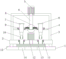
Fig. 1 is a schematic structural view of the present invention;
fig. 2 is a top view of the blanking baffle of the present invention;
FIG. 3 is a schematic structural view of the working table of the present invention;
fig. 4 is an enlarged schematic view of the structure at a in fig. 1 according to the present invention.
In the figure: the automatic feeding device comprises a supporting bottom plate 1, a working table plate 2, a supporting top frame 3, a supporting plate 4, a first motor 5, a rotating shaft 6, a screw rod 7, a top plate 8, a screw rod sleeve 9, a screw tap 10, a nut sleeve 11, a second motor 12, a discharging baffle 13, a second discharging opening 14, a supporting column 15, a first discharging opening 16, a driving gear 17 and a bearing 18.
Detailed Description
The technical solutions in the embodiments of the present invention will be described clearly and completely with reference to the accompanying drawings in the embodiments of the present invention, and it is obvious that the described embodiments are only some embodiments of the present invention, not all embodiments. Based on the embodiments in the present invention, all other embodiments obtained by a person skilled in the art without creative work belong to the protection scope of the present invention.
The utility model provides a nut processing tool for photovoltaic injection molding, as shown in figures 1-4, which comprises a supporting bottom plate 1, a working table plate 2, a supporting top frame 3 and a blanking baffle 13, four corners of the upper end surface of the supporting bottom plate 1 are welded and fixed with the working table plate 2 through supporting columns 15, the supporting top frame 3 is welded on the upper end surface of the working table plate 2, the supporting top frame 3 is in a U-shaped structure, a horizontally arranged supporting plate 4 is welded in the supporting top frame 3, a first motor 5 is installed on the top end surface of the supporting top frame 3, a shaft of the first motor 5 is connected with a rotating shaft 6 inserted in the supporting plate 4, four groups of screw sleeves 9 are installed on the upper end surface of the supporting plate 4 in a rectangular array, the four groups of screw sleeves 9 are internally threaded with screw rods 7, the bottom ends of the screw rods 7 are all connected with screw taps 10, and a rotating motor (as shown, the top of rotating the motor is fixed with the bottom welded of screw rod, and bottom crankshaft connection screw tap 10 to the rotation that the motor rotated and can drive screw tap 10 realizes carrying out the tapping to the nut, the up end of work platen 2 still is embedded to have four groups to be the nut cover 11 that the rectangle array set up, four groups nut cover 11 corresponds with the vertical coaxial of four group screw taps 10, and on the unloading baffle 13 that is equipped with between four groups nut cover 11 vertical link up to work platen 2 and the supporting baseplate 1.
Specifically, the top end of the rotating shaft 6 penetrates through the bearing 18 in the supporting top frame 3 and is welded and fixed with the crankshaft of the first motor 5, the bottom end of the rotating shaft 6 is welded and fixed with the inner wall of another group of bearings 18 in the supporting plate 4, and the driving gear 17 is fixedly sleeved on the rotating shaft 6, so that the first motor 5 rotates to drive the rotating shaft 6 to rotate on the supporting plate 4 and the supporting top frame 3, and further the driving gear 17 is driven to rotate.
Specifically, roof 8 is all installed to four groups the top of screw rod 7, avoids screw rod 7 gliding in-process downwards, from screw rod cover 9 roll-off, the top of screw rod cover 9 fixed cover has the driven gear with driving gear 17 meshing on backup pad 4, and its bottom also with embedded bearing 18's inner wall welded fastening in backup pad 4, realizes that driving gear 17 rotates and drives driven gear pivoted, makes screw rod cover 9 follow the rotation.
Specifically, the nut sleeve 11 is composed of two groups of cylindrical structures with different diameters, and is slidably inserted into a groove formed in the working table plate 2, so that the threaded sleeves 11 with different inner diameters can be replaced for different nuts, and a second vertically-through feed opening 14 is also formed in the supporting bottom plate 1 right below the groove.
Specifically, the blanking baffle 13 is of a disc-shaped structure, the top end of the blanking baffle is welded and fixed with a crankshaft of a second motor 12 installed at the center of the upper end face of the working table plate 2, four groups of first blanking ports 16 which are vertically communicated are also formed in an annular array on the upper end face of the working table plate, a tapping outlet is formed in one side of each first blanking port 16, two adjacent groups of the first blanking ports are arranged at an angle of 45 degrees, the diameter of each first blanking port is smaller than that of each first blanking port 16 and that of each screw tap 10, and waste chips generated when the screw taps.
Specifically, the four groups of grooves formed in the first feed opening 16, the second feed opening 14 and the nut sleeve 11 are in vertical coaxial correspondence, and the diameters of the first feed opening 16 and the second feed opening 14 are the same and larger than the diameter of the bottom of each groove.
Specifically, during tapping, firstly, a nut sleeve 11 with a corresponding inner diameter is selected according to the size of a nut, the nut sleeve 11 is installed in a groove of a working table plate 2, then the nut is placed in the inner diameter of the nut, then a second motor 12 is started, the second motor 12 rotates to drive a blanking baffle 13 to rotate, a tapping outlet corresponds to the nut sleeve 11 and a second blanking port 14, at the moment, a first motor 5 is started, the first motor 5 rotates forwards to drive a rotating shaft 6 to rotate, four groups of screw sleeves 9 are driven to rotate by meshing of gears, due to the fact that the screw sleeves 9 are fixed, a screw 7 in the screw is made to move downwards, the connected rotating motor and the screw tap 10 are driven to descend, the rotating motor is started to drive the screw tap 10 to rotate, when the screw tap 10 is in contact with the nut, tapping is carried out, and direct tapping is completed, the piece that its produced is discharged from tapping export, second feed opening 14, starts the reversal of first motor 5 this moment, drives screw rod 7 and reciprocates, drives screw tap 10 and leaves the nut, restarts second motor 12 and rotates 45, makes first discharge gate 16 and the coincidence of second discharge gate 14, and the bottom of nut is not at there is the supporting effect to carry out the unloading from first discharge gate 16 and second discharge gate 14 (first motor 5 and second motor 12 here are servo motor).
Finally, it should be noted that: although the present invention has been described in detail with reference to the foregoing embodiments, it will be apparent to those skilled in the art that modifications and variations can be made in the embodiments or in part of the technical features of the embodiments without departing from the spirit and the scope of the invention.
Claims (6)
1. The utility model provides a photovoltaic is nut processing frock for injection molding, includes supporting baseplate (1), work platen (2), support top frame (3) and unloading baffle (13), its characterized in that: the upper end face four corners of the supporting base plate (1) are welded and fixed with the working table plate (2) through supporting columns (15), the supporting top frame (3) is welded on the upper end face of the working table plate (2), the supporting top frame (3) is of a U-shaped structure, a horizontally arranged supporting plate (4) is welded in the supporting top frame, a first motor (5) is installed on the top end face of the supporting top frame (3), a rotating shaft (6) inserted in the supporting plate (4) is connected to a spindle of the first motor (5), four groups of screw sleeves (9) are installed on the upper end face of the supporting plate (4) in a rectangular array mode, the screw sleeves (9) are inserted into the screw rods (7) in the four groups, screw taps (10) are connected to the bottom ends of the screw rods (7), four groups of nut sleeves (11) arranged in the rectangular array mode are further embedded in the upper end face of the working base plate (2), and the four groups of nut, and the four groups of nut sleeves (11) vertically penetrate through a blanking baffle (13) arranged between the working table plate (2) and the supporting base plate (1).
2. The nut machining tool for the photovoltaic injection molded part according to claim 1, characterized in that: the top end of the rotating shaft (6) penetrates through a bearing (18) in the supporting top frame (3) to be welded and fixed with a crankshaft of the first motor (5), the bottom end of the rotating shaft (6) is welded and fixed with the inner wall of the other group of bearings (18) in the supporting plate (4), and the rotating shaft (6) is fixedly sleeved with a driving gear (17).
3. The nut machining tool for the photovoltaic injection molded part according to claim 1, characterized in that: the top of four groups screw rod (7) all installs roof (8), the top of screw rod cover (9) is fixed to overlap on backup pad (4) has the driven gear with driving gear (17) meshing, and its bottom also with the inner wall welded fastening of embedded bearing (18) in backup pad (4).
4. The nut machining tool for the photovoltaic injection molded part according to claim 1, characterized in that: the nut sleeve (11) is composed of two groups of cylindrical structures with different diameters, the nut sleeve is inserted into a groove formed in the working table plate (2) in a sliding mode, and a second vertically-through feed opening (14) is formed in the supporting base plate (1) right below the groove.
5. The nut machining tool for the photovoltaic injection molded part according to claim 1, characterized in that: the blanking baffle (13) is of a disc-shaped structure, the top end of the blanking baffle is welded and fixed with a crankshaft of a second motor (12) arranged at the center of the upper end face of the working table plate (2), and four groups of vertically through first blanking ports (16) are also arranged on the upper end face of the blanking baffle in an annular array.
6. The nut machining tool for the photovoltaic injection molded part according to claim 5, characterized in that: the four groups of grooves formed by the first feed opening (16), the second feed opening (14) and the nut sleeve (11) are in vertical coaxial correspondence, and the diameters of the first feed opening (16) and the second feed opening (14) are the same and are larger than the diameter of the bottom of each groove.
Priority Applications (1)
| Application Number | Priority Date | Filing Date | Title |
|---|---|---|---|
| CN201921615302.4U CN210937510U (en) | 2019-09-26 | 2019-09-26 | Nut processing tool for photovoltaic injection molding part |
Applications Claiming Priority (1)
| Application Number | Priority Date | Filing Date | Title |
|---|---|---|---|
| CN201921615302.4U CN210937510U (en) | 2019-09-26 | 2019-09-26 | Nut processing tool for photovoltaic injection molding part |
Publications (1)
| Publication Number | Publication Date |
|---|---|
| CN210937510U true CN210937510U (en) | 2020-07-07 |
Family
ID=71370210
Family Applications (1)
| Application Number | Title | Priority Date | Filing Date |
|---|---|---|---|
| CN201921615302.4U Expired - Fee Related CN210937510U (en) | 2019-09-26 | 2019-09-26 | Nut processing tool for photovoltaic injection molding part |
Country Status (1)
| Country | Link |
|---|---|
| CN (1) | CN210937510U (en) |
Cited By (3)
| Publication number | Priority date | Publication date | Assignee | Title |
|---|---|---|---|---|
| CN112659020A (en) * | 2020-12-18 | 2021-04-16 | 望江县天长光学仪器有限公司 | Positioning device for processing multiple optical lenses |
| CN112846738A (en) * | 2021-01-08 | 2021-05-28 | 刘君子 | Small-size nut screw rod equipment mechanism |
| CN117840483A (en) * | 2024-02-28 | 2024-04-09 | 河北同发铁路工程集团铭豪高速铁路器材制造有限公司 | Nut drilling equipment |
-
2019
- 2019-09-26 CN CN201921615302.4U patent/CN210937510U/en not_active Expired - Fee Related
Cited By (3)
| Publication number | Priority date | Publication date | Assignee | Title |
|---|---|---|---|---|
| CN112659020A (en) * | 2020-12-18 | 2021-04-16 | 望江县天长光学仪器有限公司 | Positioning device for processing multiple optical lenses |
| CN112846738A (en) * | 2021-01-08 | 2021-05-28 | 刘君子 | Small-size nut screw rod equipment mechanism |
| CN117840483A (en) * | 2024-02-28 | 2024-04-09 | 河北同发铁路工程集团铭豪高速铁路器材制造有限公司 | Nut drilling equipment |
Similar Documents
| Publication | Publication Date | Title |
|---|---|---|
| CN213507196U (en) | Carbide passivation treatment equipment | |
| CN218690947U (en) | Efficient oiling device for bolt machining | |
| CN215547383U (en) | Preprocessing device for processing photoelectric conversion adapter shell | |
| CN217698257U (en) | Solid-liquid separation centralized treatment device based on municipal sewage treatment | |
| CN222274077U (en) | Integrated cap screwing and diluting agent adding device and equipment | |
| CN112570908B (en) | Laser scribing equipment for solar cell | |
| CN219987661U (en) | Manipulator clamp for upper and lower pieces of edge-covered glass | |
| CN212398374U (en) | Multi-station gland nut tapping device | |
| CN210306725U (en) | Workbench for vertical machine tool | |
| CN216758295U (en) | Four-side processing device of CNC milling machine for automobile battery pole | |
| CN214023600U (en) | Numerical control drilling machine with positioning function for processing new energy battery box cover | |
| CN112222543B (en) | A semi-automatic nut tapping device | |
| CN214732512U (en) | Quick unloader is used to cylinder lithium cell automation line | |
| CN213560030U (en) | Processing machine tool for net rack bolt ball | |
| CN212824529U (en) | Deburring equipment | |
| CN217618209U (en) | Combined automatic nut tapping device | |
| CN221127195U (en) | Solar cell panel supporting device | |
| CN219188902U (en) | Tapping device for plastic parts | |
| CN221070031U (en) | Automatic feeding and discharging device of current collecting plate | |
| CN222359730U (en) | An automated multi-station rotary machining equipment | |
| CN216577596U (en) | Clamping mechanism of nut screwing machine | |
| CN216324861U (en) | Improved efficient thread rolling mechanism for screw | |
| CN110153750A (en) | A kind of special fixture for aluminum profile numerical control machining center | |
| CN109500422A (en) | Automatic producing device for the drilling of batch part | |
| CN220481019U (en) | Feeding device of numerical control machine tool |
Legal Events
| Date | Code | Title | Description |
|---|---|---|---|
| GR01 | Patent grant | ||
| GR01 | Patent grant | ||
| CF01 | Termination of patent right due to non-payment of annual fee |
Granted publication date: 20200707 Termination date: 20210926 |
|
| CF01 | Termination of patent right due to non-payment of annual fee |