CN210928430U - Inverter heat dissipation device for photovoltaic - Google Patents
Inverter heat dissipation device for photovoltaic Download PDFInfo
- Publication number
- CN210928430U CN210928430U CN201921771597.4U CN201921771597U CN210928430U CN 210928430 U CN210928430 U CN 210928430U CN 201921771597 U CN201921771597 U CN 201921771597U CN 210928430 U CN210928430 U CN 210928430U
- Authority
- CN
- China
- Prior art keywords
- heat
- heat dissipation
- plate
- baffle
- photovoltaic
- Prior art date
- Legal status (The legal status is an assumption and is not a legal conclusion. Google has not performed a legal analysis and makes no representation as to the accuracy of the status listed.)
- Expired - Fee Related
Links
Images


Classifications
-
- Y—GENERAL TAGGING OF NEW TECHNOLOGICAL DEVELOPMENTS; GENERAL TAGGING OF CROSS-SECTIONAL TECHNOLOGIES SPANNING OVER SEVERAL SECTIONS OF THE IPC; TECHNICAL SUBJECTS COVERED BY FORMER USPC CROSS-REFERENCE ART COLLECTIONS [XRACs] AND DIGESTS
- Y02—TECHNOLOGIES OR APPLICATIONS FOR MITIGATION OR ADAPTATION AGAINST CLIMATE CHANGE
- Y02E—REDUCTION OF GREENHOUSE GAS [GHG] EMISSIONS, RELATED TO ENERGY GENERATION, TRANSMISSION OR DISTRIBUTION
- Y02E10/00—Energy generation through renewable energy sources
- Y02E10/50—Photovoltaic [PV] energy
- Y02E10/56—Power conversion systems, e.g. maximum power point trackers
Landscapes
- Cooling Or The Like Of Electrical Apparatus (AREA)
Abstract
本实用新型提供了光伏用逆变器散热装置,属于逆变器领域,该一种光伏用逆变器散热装置,包括盒体、散热组件和隔离组件。所述盒体包括外壳和盖板,所述外壳上端面敞口设置,所述盖板安装在所述外壳的上端面。所述散热组件包括散热板、散热扇和热管,所述散热板设置在所述外壳内部,所述热管的一端与所述散热板连接;安装腔内部的元件产生的热量通过散热板外表面对外进行扩散,并通过启动散热扇带动气流,使得散热腔内的空气流动,将散热板表面的热量吹散带走,通过散热板设置在外壳内壁两侧,增强散热效果,改善外部空气直接对安装腔内的元件进行散热,降低了空气中灰尘附着在元件表层的可能性,提高了防尘能力。

The utility model provides a heat dissipation device for a photovoltaic inverter, belonging to the field of inverters. The heat dissipation device for a photovoltaic inverter comprises a box body, a heat dissipation component and an isolation component. The box body includes an outer shell and a cover plate, the upper end surface of the outer shell is provided with an opening, and the cover plate is installed on the upper end surface of the outer shell. The heat dissipation assembly includes a heat dissipation plate, a heat dissipation fan and a heat pipe, the heat dissipation plate is arranged inside the casing, and one end of the heat pipe is connected to the heat dissipation plate; the heat generated by the components inside the installation cavity passes through the outer surface of the heat dissipation plate to the outside. Diffusion is carried out, and the air flow is driven by starting the cooling fan, so that the air in the cooling cavity flows, and the heat on the surface of the cooling plate is blown away. The components in the cavity dissipate heat, which reduces the possibility of dust in the air adhering to the surface of the components and improves the dustproof capability.
Description
技术领域technical field
本实用新型涉及逆变器领域,具体而言,涉及一种光伏用逆变器散热装置。The utility model relates to the field of inverters, in particular to a heat dissipation device for a photovoltaic inverter.
背景技术Background technique
逆变器是把直流电能转变成交流电。它由逆变桥、控制逻辑和滤波电路组成。在生活中逆变器的使用非常广泛,但是逆变器的使用通常会产生热量,从而使逆变器的温度升高,需要通过安装散热装置进行散热。The inverter converts DC power into AC power. It consists of inverter bridge, control logic and filter circuit. The use of inverters is very extensive in life, but the use of inverters usually generates heat, which increases the temperature of the inverter and needs to be dissipated by installing a heat sink.
现有的散热组件是发热部件通过热管连接散热片,通过散热风扇带动气流加快散热片热量的扩散,散热效率低,且防尘效果差,导致壳体内壁灰尘覆盖于零部件表面,造成散热隐患。The existing heat dissipation component is that the heat generating component is connected to the heat sink through a heat pipe, and the air flow is driven by a cooling fan to speed up the heat dissipation of the heat sink. .
实用新型内容Utility model content
为了弥补以上不足,本实用新型提供了一种光伏用逆变器散热装置,旨在改善散热效率低,且防尘效果差的问题。In order to make up for the above deficiencies, the present invention provides a heat dissipation device for a photovoltaic inverter, which aims to improve the problems of low heat dissipation efficiency and poor dustproof effect.
本实用新型是这样实现的:The utility model is realized in this way:
一种光伏用逆变器散热装置,包括盒体、散热组件和隔离组件。A heat dissipation device for a photovoltaic inverter includes a box body, a heat dissipation component and an isolation component.
所述盒体包括外壳和盖板,所述外壳上端面敞口设置,所述盖板安装在所述外壳的上端面。The box body includes an outer shell and a cover plate, the upper end surface of the outer shell is provided with an opening, and the cover plate is installed on the upper end surface of the outer shell.
所述散热组件包括散热板、散热扇和热管,所述散热板设置在所述外壳内部,所述热管的一端与所述散热板连接,所述散热扇固定于所述外壳一端。The heat dissipation assembly includes a heat dissipation plate, a heat dissipation fan and a heat pipe, the heat dissipation plate is arranged inside the casing, one end of the heat pipe is connected to the heat dissipation plate, and the heat dissipation fan is fixed to one end of the casing.
所述隔离组件包括第一挡板和第二挡板,所述第一挡板和所述第二挡板固定在所述外壳底部,两个所述散热板对称设置在所述外壳两侧,两个所述散热板与所述第一挡板以及所述第二挡板形成环形封闭的安装腔。The isolation assembly includes a first baffle plate and a second baffle plate, the first baffle plate and the second baffle plate are fixed on the bottom of the casing, and the two cooling plates are symmetrically arranged on both sides of the casing, The two heat dissipation plates, the first baffle plate and the second baffle plate form an annular closed installation cavity.
两个所述散热板与所述外壳内壁之间形成散热腔,所述第二挡板的两端与所述外壳内壁之间形成散热口,所述散热口与所述散热腔连通。A heat dissipation cavity is formed between the two heat dissipation plates and the inner wall of the casing, and a heat dissipation port is formed between two ends of the second baffle plate and the inner wall of the casing, and the heat dissipation port is communicated with the heat dissipation cavity.
在本实用新型的一种实施例中,所述外壳的底部设置有底座,所述底座与所述外壳的下表面卡接,所述底座表面开设有安装孔。In an embodiment of the present invention, the bottom of the casing is provided with a base, the base is clamped with the lower surface of the casing, and a mounting hole is opened on the surface of the base.
在本实用新型的一种实施例中,所述外壳下表面开设有卡槽,所述底座上表面固定有卡块,所述卡块与所述卡槽卡接。In an embodiment of the present invention, a clamping slot is formed on the lower surface of the casing, a clamping block is fixed on the upper surface of the base, and the clamping block is clamped with the clamping slot.
在本实用新型的一种实施例中,所述散热板包括导热板和散热翅片,所述散热翅片设置在所述导热板外表面,所述散热翅片与所述导热板焊接固定连接。In an embodiment of the present invention, the heat dissipation plate includes a heat conduction plate and a heat dissipation fin, the heat dissipation fin is arranged on the outer surface of the heat conduction plate, and the heat dissipation fin is welded and fixedly connected to the heat conduction plate .
在本实用新型的一种实施例中,所述热管的一端通过螺栓固定在所述导热板内表面,所述热管与所述导热板连接处涂有导热硅脂。In an embodiment of the present invention, one end of the heat pipe is fixed on the inner surface of the heat-conducting plate by means of bolts, and the connection between the heat pipe and the heat-conducting plate is coated with heat-conducting silicone grease.
在本实用新型的一种实施例中,所述导热板的两端分别与所述第一挡板和所述第二挡板的端部卡接。In an embodiment of the present invention, two ends of the heat conducting plate are respectively clamped with the ends of the first baffle plate and the second baffle plate.
在本实用新型的一种实施例中,所述第一挡板和所述第二挡板的内壁上均开设有定位槽,所述导热板的两端固定焊接有定位块,所述定位块插接于所述定位槽内。In an embodiment of the present invention, positioning grooves are provided on the inner walls of the first baffle plate and the second baffle plate, and positioning blocks are fixedly welded at both ends of the heat-conducting plate, and the positioning blocks inserted into the positioning groove.
在本实用新型的一种实施例中,所述第一挡板和所述第二挡板与所述外壳的底部为一体成型结构。In an embodiment of the present invention, the first baffle plate and the second baffle plate are integrally formed with the bottom of the casing.
在本实用新型的一种实施例中,所述外壳上端面开设有螺纹孔,所述盖板上表面开设的沉孔内插接有螺丝,所述螺丝的下端与所述螺纹孔螺纹连接。In an embodiment of the present invention, the upper end surface of the casing is provided with threaded holes, the countersunk holes provided on the upper surface of the cover plate are inserted with screws, and the lower ends of the screws are threadedly connected to the threaded holes.
在本实用新型的一种实施例中,所述外壳的一端开设有通孔,所述散热扇固定在所述通孔内,所述通孔外端口设置有防尘网板,所述防尘网板表面阵列开设有网孔。In an embodiment of the present invention, a through hole is opened at one end of the casing, the cooling fan is fixed in the through hole, and a dustproof mesh plate is arranged at the outer port of the through hole, and the dustproof The surface array of the mesh plate is provided with mesh holes.
本实用新型的有益效果是:本实用新型通过上述设计得到的一种光伏用逆变器散热装置,使用时,安装腔内部的元件产生的热量通过散热板外表面对外进行扩散,并通过启动散热扇带动气流,使得散热腔内的空气流动,将散热板表面的热量吹散带走,通过散热板设置在外壳内壁两侧,增大了散热面积,增强散热效果,改善外部空气直接对安装腔内的元件进行散热,降低了空气中灰尘附着在元件表层的可能性,提高了防尘能力。The beneficial effects of the present invention are: the heat dissipation device for photovoltaic inverters obtained by the present invention through the above design, when in use, the heat generated by the components inside the installation cavity is diffused to the outside through the outer surface of the heat dissipation plate, and the heat is dissipated by starting the heat dissipation. The fan drives the airflow to make the air flow in the heat dissipation cavity, and the heat on the surface of the heat dissipation plate is blown away and taken away. The internal components dissipate heat, reduce the possibility of dust in the air adhering to the surface of the components, and improve the dustproof ability.
附图说明Description of drawings
为了更清楚地说明本实用新型实施方式的技术方案,下面将对实施方式中所需要使用的附图作简单地介绍,应当理解,以下附图仅示出了本实用新型的某些实施例,因此不应被看作是对范围的限定,对于本领域普通技术人员来讲,在不付出创造性劳动的前提下,还可以根据这些附图获得其他相关的附图。In order to illustrate the technical solutions of the embodiments of the present invention more clearly, the accompanying drawings required in the embodiments will be briefly introduced below. It should be understood that the following drawings only show some embodiments of the present invention. Therefore, it should not be regarded as a limitation of the scope. For those of ordinary skill in the art, other related drawings can also be obtained from these drawings without any creative effort.
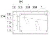
图1是本实用新型实施方式提供的结构示意图;1 is a schematic structural diagram provided by an embodiment of the present invention;
图2为本实用新型实施方式提供的盒体结构示意图;2 is a schematic structural diagram of a box body provided by an embodiment of the present invention;
图3为本实用新型实施方式提供的散热板结构示意图;3 is a schematic structural diagram of a heat dissipation plate provided by an embodiment of the present invention;
图4为本实用新型实施方式提供的图1中A处结构示意图。FIG. 4 is a schematic diagram of the structure at A in FIG. 1 according to an embodiment of the present invention.
图中:100-盒体;110-外壳;111-卡槽;113-散热口;115-螺纹孔;117-防尘网板;130-盖板;131-螺丝;150-底座;151-卡块;300-散热组件;310-散热板;311-导热板;313-散热翅片;315-定位块;330-散热扇;350-热管;500-隔离组件;510-第一挡板;530-第二挡板;540-定位槽;700-安装腔;900-散热腔。In the figure: 100-box body; 110-shell; 111-card slot; 113-radiation port; 115-threaded hole; 117-dust screen plate; 130-cover plate; 131-screw; 150-base; block; 300-heat dissipation assembly; 310-heat dissipation plate; 311-thermal conduction plate; 313-heat dissipation fin; 315-positioning block; 330-heat dissipation fan; 350-heat pipe; 500-isolation assembly; 510-first baffle; 530 -Second baffle; 540-positioning slot; 700-installation cavity; 900-heat dissipation cavity.
具体实施方式Detailed ways
为使本实用新型实施方式的目的、技术方案和优点更加清楚,下面将结合本实用新型实施方式中的附图,对本实用新型实施方式中的技术方案进行清楚、完整地描述,显然,所描述的实施方式是本实用新型一部分实施方式,而不是全部的实施方式。基于本实用新型中的。实施方式,本领域普通技术人员在没有作出创造性劳动前提下所获得的所有其他实施方式,都属于本实用新型保护的范围。In order to make the purposes, technical solutions and advantages of the embodiments of the present invention more clear, the technical solutions in the embodiments of the present invention will be clearly and completely described below with reference to the accompanying drawings in the embodiments of the present invention. Obviously, the described The embodiments of the present invention are a part of the embodiments of the present invention, but not all of the embodiments. Based on the present invention. Embodiments, and all other embodiments obtained by those of ordinary skill in the art without creative work, fall within the protection scope of the present invention.
因此,以下对在附图中提供的本实用新型的实施方式的详细描述并非旨在限制要求保护的本实用新型的范围,而是仅仅表示本实用新型的选定实施方式。基于本实用新型中的实施方式,本领域普通技术人员在没有作出创造性劳动前提下所获得的所有其他实施方式,都属于本实用新型保护的范围。Accordingly, the following detailed description of the embodiments of the invention provided in the accompanying drawings is not intended to limit the scope of the invention as claimed, but is merely representative of selected embodiments of the invention. Based on the embodiments of the present invention, all other embodiments obtained by those of ordinary skill in the art without creative work fall within the protection scope of the present invention.
应注意到:相似的标号和字母在下面的附图中表示类似项,因此,一旦某一项在一个附图中被定义,则在随后的附图中不需要对其进行进一步定义和解释。It should be noted that like numerals and letters refer to like items in the following figures, so once an item is defined in one figure, it does not require further definition and explanation in subsequent figures.
在本实用新型的描述中,需要理解的是,术语“中心”、“纵向”、“横向”、“长度”、“宽度”、“厚度”、“上”、“下”、“前”、“后”、“左”、“右”、“竖直”、“水平”、“顶”、“底”、“内”、“外”、“顺时针”、“逆时针”等指示的方位或位置关系为基于附图所示的方位或位置关系,仅是为了便于描述本实用新型和简化描述,而不是指示或暗示所指的设备或元件必须具有特定的方位、以特定的方位构造和操作,因此不能理解为对本实用新型的限制。In the description of the present invention, it should be understood that the terms "center", "longitudinal", "lateral", "length", "width", "thickness", "upper", "lower", "front", "Back", "Left", "Right", "Vertical", "Horizontal", "Top", "Bottom", "Inner", "Outer", "Clockwise", "Counterclockwise" etc. Or the positional relationship is based on the orientation or positional relationship shown in the accompanying drawings, which is only for the convenience of describing the present invention and simplifying the description, rather than indicating or implying that the referred device or element must have a specific orientation, be constructed in a specific orientation and operation, so it cannot be construed as a limitation to the present invention.
此外,术语“第一”、“第二”仅用于描述目的,而不能理解为指示或暗示相对重要性或者隐含指明所指示的技术特征的数量。由此,限定有“第一”、“第二”的特征可以明示或者隐含地包括一个或者更多个该特征。在本实用新型的描述中,“多个”的含义是两个或两个以上,除非另有明确具体的限定。In addition, the terms "first" and "second" are only used for descriptive purposes, and should not be construed as indicating or implying relative importance or implying the number of indicated technical features. Thus, a feature defined as "first" or "second" may expressly or implicitly include one or more of that feature. In the description of the present invention, "plurality" means two or more, unless otherwise expressly and specifically defined.
在本实用新型中,除非另有明确的规定和限定,术语“安装”、“相连”、“连接”、“固定”等术语应做广义理解,例如,可以是固定连接,也可以是可拆卸连接,或成一体;可以是直接相连,也可以通过中间媒介间接相连,可以是两个元件内部的连通或两个元件的相互作用关系。对于本领域的普通技术人员而言,可以根据具体情况理解上述术语在本实用新型中的具体含义。In the present utility model, unless otherwise expressly specified and limited, the terms "installation", "connection", "connection", "fixed" and other terms should be understood in a broad sense, for example, it may be a fixed connection or a detachable connection Connection, or integration; it can be directly connected, or indirectly connected through an intermediate medium, and it can be the internal communication between two elements or the interaction relationship between the two elements. For those of ordinary skill in the art, the specific meanings of the above terms in the present invention can be understood according to specific situations.
在本实用新型中,除非另有明确的规定和限定,第一特征在第二特征之“上”或之“下”可以包括第一和第二特征直接接触,也可以包括第一和第二特征不是直接接触而是通过它们之间的另外的特征接触。而且,第一特征在第二特征“之上”、“上方”和“上面”包括第一特征在第二特征正上方和斜上方,或仅仅表示第一特征水平高度高于第二特征。第一特征在第二特征“之下”、“下方”和“下面”包括第一特征在第二特征正下方和斜下方,或仅仅表示第一特征水平高度小于第二特征。In the present invention, unless otherwise expressly specified and limited, a first feature "on" or "under" a second feature may include the first and second features in direct contact, or may include the first and second features The features are not in direct contact but through additional features between them. Also, the first feature being "above", "over" and "above" the second feature includes the first feature being directly above and obliquely above the second feature, or simply means that the first feature is level higher than the second feature. The first feature is "below", "below" and "below" the second feature includes the first feature is directly below and diagonally below the second feature, or simply means that the first feature has a lower level than the second feature.
实施例Example
请参阅图1-4,本实用新型提供一种技术方案:一种光伏用逆变器散热装置,包括盒体100、散热组件300和隔离组件500。Referring to FIGS. 1-4 , the present invention provides a technical solution: a heat dissipation device for a photovoltaic inverter, comprising a
请参阅图2,盒体100包括外壳110和盖板130,外壳110上端面敞口设置,盖板130安装在外壳110的上端面。外壳110的底部设置有底座150,底座150与外壳110的下表面卡接,底座150表面开设有安装孔,通过设置底座150便于外壳110的安装固定,外壳110下表面开设有卡槽111,底座150上表面固定有卡块151,其中卡块151与底座150焊接连接,卡块151与卡槽111卡接,外壳110与底座150通过卡接固定连接,便于拆卸。Referring to FIG. 2 , the
请继续参阅图2,外壳110上端面开设有螺纹孔115,盖板130上表面开设的沉孔内插接有螺丝131,螺丝131的下端与螺纹孔115螺纹连接,便于外壳110与盖板130连接固定。Please continue to refer to FIG. 2 , a threaded
请参阅图3-4,散热组件300包括散热板310、散热扇330和热管350,散热板310设置在外壳110内部,散热板310包括导热板311和散热翅片313,散热翅片313设置在导热板311外表面,散热翅片313与导热板311焊接固定连接,通过设置散热翅片313,便于对导热板311自身的热量对外扩散,增大散热速率,热管350的一端与散热板310连接,热管350的一端通过螺栓固定在导热板311内表面,热管350与导热板311连接处涂有导热硅脂,通过螺栓连接,便于拆装及更换零部件,通过设置导热硅脂,使得热管350与导热板311连接良好,便于热传递,散热扇330固定于外壳110一端,外壳110的一端开设有通孔,散热扇330通过螺栓固定在通孔内,通孔外端口设置有防尘网板117,防尘网板117表面阵列开设有网孔。3-4, the
请继续参阅图1,隔离组件500包括第一挡板510和第二挡板530,第一挡板510和第二挡板530固定在外壳110底部,第一挡板510和第二挡板530与外壳110的底部为一体成型结构,提高各结构之间的连接强度,防止松动影响使用,两个散热板310对称设置在外壳110两侧,两个散热板310与第一挡板510以及第二挡板530形成环形封闭的安装腔700。Please continue to refer to FIG. 1 , the
其次,两个散热板310与外壳110内壁之间形成散热腔900,第二挡板530的两端与外壳110内壁之间形成散热口113,散热口113与散热腔900连通。Next, a
在具体设置时,导热板311的两端分别与第一挡板510和第二挡板530的端部卡接,第一挡板510和第二挡板530的内壁上均开设有定位槽540,导热板311的两端固定焊接有定位块315,定位块315插接于定位槽540内,便于散热板310的安装拆卸,便于维护使用。During the specific setting, both ends of the
该一种光伏用逆变器散热装置的工作原理:使用时,通过设置安装腔700,便于将电器元件固定在安装腔700内,通过热管350与待散热元件进行连接,将热量传递至散热板310,安装腔700内部的元件产生的热量通过散热板310外表面对外进行扩散,并通过启动散热扇330带动气流,使得散热腔900内的空气流动,将散热板310表面的热量吹散带走,通过散热板310设置在外壳110内壁两侧,增大了散热面积,增强散热效果,改善外部空气直接对安装腔700内的元件进行散热,降低了空气中灰尘附着在元件表层的可能性,提高了防尘能力。The working principle of the heat dissipation device for a photovoltaic inverter: when in use, the
需要说明的是,散热扇330具体的型号规格需根据该装置的实际规格等进行选型确定,具体选型计算方法采用本领域现有技术,故不再详细赘述。It should be noted that the specific model and specifications of the cooling
散热扇330的供电及其原理对本领域技术人员来说是清楚的,在此不予详细说明。The power supply of the cooling
以上所述仅为本实用新型的优选实施方式而已,并不用于限制本实用新型,对于本领域的技术人员来说,本实用新型可以有各种更改和变化。凡在本实用新型的精神和原则之内,所作的任何修改、等同替换、改进等,均应包含在本实用新型的保护范围之内。The above descriptions are only preferred embodiments of the present invention, and are not intended to limit the present invention. For those skilled in the art, the present invention may have various modifications and changes. Any modification, equivalent replacement, improvement, etc. made within the spirit and principle of the present invention shall be included in the protection scope of the present invention.
Claims (10)
Priority Applications (1)
| Application Number | Priority Date | Filing Date | Title |
|---|---|---|---|
| CN201921771597.4U CN210928430U (en) | 2019-10-21 | 2019-10-21 | Inverter heat dissipation device for photovoltaic |
Applications Claiming Priority (1)
| Application Number | Priority Date | Filing Date | Title |
|---|---|---|---|
| CN201921771597.4U CN210928430U (en) | 2019-10-21 | 2019-10-21 | Inverter heat dissipation device for photovoltaic |
Publications (1)
| Publication Number | Publication Date |
|---|---|
| CN210928430U true CN210928430U (en) | 2020-07-03 |
Family
ID=71366473
Family Applications (1)
| Application Number | Title | Priority Date | Filing Date |
|---|---|---|---|
| CN201921771597.4U Expired - Fee Related CN210928430U (en) | 2019-10-21 | 2019-10-21 | Inverter heat dissipation device for photovoltaic |
Country Status (1)
| Country | Link |
|---|---|
| CN (1) | CN210928430U (en) |
Cited By (1)
| Publication number | Priority date | Publication date | Assignee | Title |
|---|---|---|---|---|
| CN114610125A (en) * | 2022-04-18 | 2022-06-10 | 安徽科达自动化集团股份有限公司 | Dustproof heat dissipation formula industrial control, detection machine case |
-
2019
- 2019-10-21 CN CN201921771597.4U patent/CN210928430U/en not_active Expired - Fee Related
Cited By (1)
| Publication number | Priority date | Publication date | Assignee | Title |
|---|---|---|---|---|
| CN114610125A (en) * | 2022-04-18 | 2022-06-10 | 安徽科达自动化集团股份有限公司 | Dustproof heat dissipation formula industrial control, detection machine case |
Similar Documents
| Publication | Publication Date | Title |
|---|---|---|
| CN204721777U (en) | Electronic device and liquid cooling type heat dissipation structure thereof | |
| CN203279443U (en) | Electric cabinet and air conditioner possessing same | |
| CN217283820U (en) | Power supply with air cooling and liquid cooling device | |
| WO2023035861A1 (en) | Server | |
| WO2019227393A1 (en) | Heat dissipating system and photographic device | |
| CN215188051U (en) | Heat dissipation module, electronic equipment and energy storage equipment | |
| CN104679175A (en) | Dustproof radiating machine case | |
| CN118174515A (en) | Power conversion equipment and energy storage equipment | |
| CN209707859U (en) | A liquid crystal display module with heat dissipation structure | |
| CN210605614U (en) | Heat abstractor for computer machine case | |
| CN113727589B (en) | Water-cooling heat dissipation device | |
| CN212085467U (en) | A power distribution cabinet for a command platform | |
| CN211180755U (en) | A radiator with multiple heat dissipation | |
| CN217770015U (en) | Solar charging controller | |
| CN218918062U (en) | High-efficiency heat radiation module and notebook computer | |
| CN211857369U (en) | High-efficient heat dissipation machine case | |
| CN116249029A (en) | A 1U rack-mounted high-speed switch structure with mixed liquid cooling and air cooling | |
| CN210899817U (en) | Circuit board module with high-efficiency heat dissipation | |
| CN204968331U (en) | Power supply heat sinking device and power module | |
| CN212846622U (en) | Airtight machine case with high radiating efficiency | |
| CN211124821U (en) | A LED screen with good heat dissipation effect | |
| CN210157562U (en) | Quick heat abstractor is used to electronic product | |
| CN210226051U (en) | Composite embedded radiating fin | |
| CN218831066U (en) | Air-cooled heat conduction type spliced LED display device | |
| CN215071792U (en) | Intelligent tower UPS power fast cooling structure |
Legal Events
| Date | Code | Title | Description |
|---|---|---|---|
| GR01 | Patent grant | ||
| GR01 | Patent grant | ||
| CF01 | Termination of patent right due to non-payment of annual fee | ||
| CF01 | Termination of patent right due to non-payment of annual fee |
Granted publication date: 20200703 |