CN210926747U - Box-type substation - Google Patents
Box-type substation Download PDFInfo
- Publication number
- CN210926747U CN210926747U CN201922076640.1U CN201922076640U CN210926747U CN 210926747 U CN210926747 U CN 210926747U CN 201922076640 U CN201922076640 U CN 201922076640U CN 210926747 U CN210926747 U CN 210926747U
- Authority
- CN
- China
- Prior art keywords
- box
- fixedly connected
- channel
- substation
- transformer substation
- Prior art date
- Legal status (The legal status is an assumption and is not a legal conclusion. Google has not performed a legal analysis and makes no representation as to the accuracy of the status listed.)
- Active
Links
- 239000000428 dust Substances 0.000 claims abstract description 18
- 238000010438 heat treatment Methods 0.000 claims description 13
- 238000007789 sealing Methods 0.000 claims description 3
- 230000017525 heat dissipation Effects 0.000 abstract description 6
- 238000009423 ventilation Methods 0.000 abstract description 6
- 230000009286 beneficial effect Effects 0.000 abstract description 2
- 238000010276 construction Methods 0.000 description 2
- 230000009466 transformation Effects 0.000 description 2
- 241000238631 Hexapoda Species 0.000 description 1
- 229910000831 Steel Inorganic materials 0.000 description 1
- 239000004744 fabric Substances 0.000 description 1
- 238000009434 installation Methods 0.000 description 1
- 239000010959 steel Substances 0.000 description 1
Images

Landscapes
- Patch Boards (AREA)
Abstract
The utility model discloses a box-type substation, including box and transformer substation body, box bottom fixedly connected with base, transformer substation body sets up at the base upper surface, transformer substation body is located the box, box top central point puts fixedly connected with input channel, the equal fixedly connected with shutter of input channel both ends port department, one side of two shutters all is equipped with first dust screen, one side of two first dust screens all is equipped with the hot plate, be equipped with inlet air channel between two hot plates, inlet air channel is located the first fan of the inside one end fixedly connected with of box, the box both sides all are equipped with the louvre, equal fixedly connected with air exhaust channel on the inner wall of box both sides, two equal fixedly connected with second dust screens of the passageway inner wall of airing exhaust, the utility model discloses the beneficial effect who reaches is: the utility model discloses guaranteed good ventilation and the good heat dissipation of transformer substation body in the box, the moisture with in the box that simultaneously can be fine is got rid of, provides good operational environment for the transformer substation body.
Description
Technical Field
The utility model relates to a box-type substation belongs to distribution technical field.
Background
The box-type substation is also called a pre-installed substation or a pre-installed substation. The high-voltage switch equipment, the distribution transformer and the low-voltage distribution device are factory prefabricated indoor and outdoor compact distribution equipment which are integrated according to a certain wiring scheme, namely, the functions of transformer voltage reduction, low-voltage distribution and the like are organically combined together and are arranged in a steel structure box which is damp-proof, rust-proof, dust-proof, rat-proof, fireproof, anti-theft, heat-insulating, totally-closed and movable. The box-type transformer substation is suitable for mines, factory enterprises, oil-gas fields and wind power stations, replaces the original civil power distribution room and power distribution station, and becomes a novel complete set of power transformation and distribution device. The box-type transformer substation is suitable for residential districts, urban public transformer substations, busy cities, construction power supplies and the like, and a user can select the box-type transformer substation according to different use conditions and load grades. Since the advent of box-type substations, the development of which has been extremely rapid, has been 70% of distribution transformers in developed countries in europe and 90% in the united states. The rapid development of modern construction of cities in China and the continuous updating and transformation of urban power distribution networks are certainly widely applied.
The auxiliary substation body that present open-air installation's block terminal can not be fine dispels the heat, especially in hot day, can not be timely with the heat discharge box can seriously influence the life of substation body, rainy day, need prevent that the box in moisture is overweight, guarantees good ventilation in the box to guarantee the operational environment of transformer substation, further guarantee the life of substation body.
SUMMERY OF THE UTILITY MODEL
The utility model aims at solving and having the auxiliary substation body that can not be fine among the prior art and in time distributing away the heat when carrying out the heat dissipation to get rid of that the moisture in the box can not be timely, the relatively poor shortcoming of ventilation, and a box-type substation who proposes.
In order to achieve the above purpose, the utility model adopts the following technical scheme:
a box-type transformer substation is designed, and comprises a box body and a transformer substation body, wherein the bottom end of the box body is fixedly connected with a base, the transformer substation body is arranged on the upper surface of the base, the transformer substation body is positioned in the box body, an input channel is fixedly connected to the central position of the top end of the box body, shutters are fixedly connected to both end ports of the input channel, one side of each shutter is provided with a first dust screen, one side of each first dust screen is provided with a heating plate, an air inlet channel is arranged between the two heating plates, one end of the air inlet channel positioned in the box body is fixedly connected with a first fan, heat dissipation holes are arranged on both sides of the box body, air exhaust channels are fixedly connected to the inner walls on both sides of the box body, a second dust screen is fixedly connected to the inner walls of the two air exhaust channels, and a drainage channel is arranged between each two second fans and the corresponding second dust screens, and each drainage channel penetrates through the box body.
Preferably, the two drainage channels have the same width as the corresponding exhaust channels.
Preferably, both of the louver blades are disposed downward.
Preferably, the surface areas of the openings of the two air exhaust channels are larger than the areas of the corresponding heat dissipation holes.
Preferably, the two drainage channels are fixedly connected with a screen at one end port outside the tank body.
Preferably, the contact surfaces of the two drainage channels and the box body are provided with sealing rings.
The utility model provides a box-type substation, beneficial effect lies in:
1. the utility model discloses all be equipped with the passageway of airing exhaust at box both sides inner wall, all establish the second fan in two passageways of airing exhaust, two passageways of airing exhaust are corresponding with the louvre, through two second fans, pass through the passageway of airing exhaust and the louvre discharge box that correspond with the heat that body of transformer substation gived off in the box, prevent that the box internal temperature is too high, all be equipped with drainage channel bottom two passageways of airing exhaust simultaneously, rainy day, when having a little rainwater to get into the passageway of airing exhaust through the louvre, the rainwater can be through two drainage channel discharge boxes, prevent that the rainwater from entering into in the box, it is unexpected to take place.
2. The utility model discloses put fixedly connected with input channel at box top central point, equal fixedly connected with shutter of input channel both ends port department, the inside symmetry of input channel is equipped with two first dust screens and two hot plates, be equipped with inlet air duct between two hot plates, inlet air duct is located the one end of box and is equipped with first fan, through first fan, can assist the transformer substation body to dispel the heat, keep the ventilation in the box, when rainy day, when there is moisture in the box, two second fans and the cooperation of first fan can be with moisture discharge, start two hot plates simultaneously, the air current through the hot plate obtains the heating, the air current after the heating enters into the box through first fan, further get rid of the moisture in the box, guarantee the good operational environment of transformer substation body.
Drawings
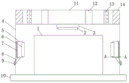
Fig. 1 is a schematic front structural view of a box-type substation provided by the present invention;
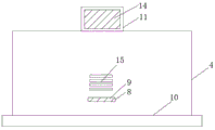
fig. 2 is a schematic side view of a box-type substation according to the present invention;
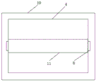
fig. 3 is a schematic top view of a box-type substation according to the present invention;
fig. 4 is a sectional view of a side a-a of an exhaust passage of a box-type substation.
In the figure: the transformer substation comprises a transformer substation body 1, a first fan 2, an air inlet channel 3, a box body 4, an air exhaust channel 5, a second fan 6, a second dust screen 7, a drainage channel 8, a screen 9, a base 10, an input channel 11, a heating plate 12, a first dust screen 13, a shutter 14 and radiating holes 15.
Detailed Description
The technical solutions in the embodiments of the present invention will be described clearly and completely with reference to the accompanying drawings in the embodiments of the present invention, and it is obvious that the described embodiments are only some embodiments of the present invention, not all embodiments.
Referring to fig. 1-4, a box-type substation comprises a box body 4 and a substation body 1, wherein the bottom end of the box body 4 is fixedly connected with a base 10, the substation body 1 is arranged on the upper surface of the base 10, the substation body 1 is positioned in the box body 4, an input channel 11 is fixedly connected with the central position of the top end of the box body 4, two end ports of the input channel 11 are fixedly connected with shutters 14, one side of each shutter 14 is provided with a first dust screen 13, one side of each first dust screen 13 is provided with a heating plate 12, an air inlet channel 3 is arranged between the two heating plates 12, one end of the air inlet channel 3 positioned in the box body 4 is fixedly connected with a first fan 2, two sides of the box body 4 are provided with radiating holes 15, the inner walls of two sides of the box body 4 are fixedly connected with air exhaust channels 5, the inner walls of two air exhaust channels 5 are fixedly connected with second dust screens 7, all be equipped with drainage channel 8 between two second fans 6 and the corresponding second dust screen 7, two drainage channel 8 all run through box 4, can assist the transformer substation body 1 to dispel the heat through first fan 2 and two second fans 6, simultaneously timely with heat exhaust box 4, good ventilation and the good heat dissipation of transformer substation body 1 in the box 4 have been guaranteed, also can get rid of the moisture in the box 4 simultaneously, start two hot plates 12, the air current obtains the heating when passing through hot plate 12, the air current after the heating enters into in the box 4 through first fan 2, can further get rid of the moisture in the box 4, guarantee the good operational environment of transformer substation body 1.
Two drainage channel 8 all with correspond 5 equal width of air exhaust channel, guarantee to enter into the rainwater in the air exhaust channel 5 and can all pass through drainage pipe discharge box 4, 14 blades of two shutter all set up down, prevent that the rainwater from entering into the input pipeline in, two 5 opening surface areas of air exhaust channel all are greater than the area that corresponds louvre 15, prevent that the rainwater from entering into box 4 through louvre 15, two drainage channel 8 are located the equal fixedly connected with screen cloth 9 of the outer one end port department of box 4, prevent that large-scale insect from entering into box 4 in, especially mouse, two drainage channel 8 all are equipped with the sealing washer with the contact surface of box 4, prevent that the rainwater from entering.
The working principle is as follows: when using, can assist the transformer substation body 1 to dispel the heat through first fan 2 and two second fans 6, simultaneously timely discharge the heat box 4, good ventilation and the good heat dissipation of transformer substation body 1 in the box 4 have been guaranteed, the humidity in the box 4 also can be got rid of simultaneously, start two hot plates 12, the air current obtains heating when passing through hot plate 12, the air current after the heating enters into the box 4 through first fan 2, can further get rid of the humidity in the box 4, guarantee the good operational environment of transformer substation body 1, simultaneously all be equipped with drainage channel 8 in two exhaust channel 5 bottoms, rainy day, when having a little rainwater to enter into exhaust channel 5 through louvre 15, the rainwater can be through two drainage channel 8 discharge box 4, prevent that the rainwater from entering into in the box 4.
The above, only be the concrete implementation of the preferred embodiment of the present invention, but the protection scope of the present invention is not limited thereto, and any person skilled in the art is in the technical scope of the present invention, according to the technical solution of the present invention and the utility model, the concept of which is equivalent to replace or change, should be covered within the protection scope of the present invention.
Claims (6)
1. A box-type substation comprises a box body (4) and a substation body (1), and is characterized in that a base (10) is fixedly connected to the bottom end of the box body (4), the substation body (1) is arranged on the upper surface of the base (10), the substation body (1) is positioned in the box body (4), an input channel (11) is fixedly connected to the center position of the top end of the box body (4), shutters (14) are fixedly connected to ports of two ends of the input channel (11), first dust screens (13) are arranged on one sides of the two shutters (14), heating plates (12) are arranged on one sides of the two first dust screens (13), an air inlet channel (3) is arranged between the two heating plates (12), a first fan (2) is fixedly connected to one end of the air inlet channel (3) positioned in the radiating hole (4), and first fans (15) are arranged on two sides of the box body (4), equal fixedly connected with air exhaust channel (5), two on box (4) both sides inner wall the equal fixedly connected with second dust screen (7) of air exhaust channel (5) inner wall, two the equal fixedly connected with second fan (6) of one end that corresponds louvre (15) is kept away from in air exhaust channel (5), two all be equipped with drainage channel (8), two between second fan (6) and the corresponding second dust screen (7) drainage channel (8) all run through box (4).
2. A box substation according to claim 1, characterized in that both of the drainage channels (8) are of the same width as the corresponding exhaust channel (5).
3. A box substation according to claim 1, characterized in that both of the louver (14) blades are arranged downwards.
4. A box substation according to claim 1, characterized in that the surface area of the openings of both exhaust channels (5) is larger than the area of the corresponding louvers (15).
5. A box substation according to claim 1, characterized in that both end ports of the two drainage channels (8) outside the box body (4) are fixedly connected with a screen (9).
6. A box substation according to claim 1, characterized in that the contact surfaces of both drainage channels (8) and the box body (4) are provided with sealing rings.
Priority Applications (1)
| Application Number | Priority Date | Filing Date | Title |
|---|---|---|---|
| CN201922076640.1U CN210926747U (en) | 2019-11-27 | 2019-11-27 | Box-type substation |
Applications Claiming Priority (1)
| Application Number | Priority Date | Filing Date | Title |
|---|---|---|---|
| CN201922076640.1U CN210926747U (en) | 2019-11-27 | 2019-11-27 | Box-type substation |
Publications (1)
| Publication Number | Publication Date |
|---|---|
| CN210926747U true CN210926747U (en) | 2020-07-03 |
Family
ID=71367022
Family Applications (1)
| Application Number | Title | Priority Date | Filing Date |
|---|---|---|---|
| CN201922076640.1U Active CN210926747U (en) | 2019-11-27 | 2019-11-27 | Box-type substation |
Country Status (1)
| Country | Link |
|---|---|
| CN (1) | CN210926747U (en) |
Cited By (1)
| Publication number | Priority date | Publication date | Assignee | Title |
|---|---|---|---|---|
| CN113690758A (en) * | 2021-09-09 | 2021-11-23 | 芜湖金牛电气股份有限公司 | Box body heat dissipation device of box-type substation |
-
2019
- 2019-11-27 CN CN201922076640.1U patent/CN210926747U/en active Active
Cited By (1)
| Publication number | Priority date | Publication date | Assignee | Title |
|---|---|---|---|---|
| CN113690758A (en) * | 2021-09-09 | 2021-11-23 | 芜湖金牛电气股份有限公司 | Box body heat dissipation device of box-type substation |
Similar Documents
| Publication | Publication Date | Title |
|---|---|---|
| CN105525935A (en) | Combined and closed subway station ventilation and air conditioning system and application thereof | |
| CN108288834A (en) | A kind of photovoltaic preassembled transformer station device | |
| CN202042808U (en) | A landscape-type fully assembled box-type substation box roof | |
| CN209881210U (en) | A prefabricated power distribution room | |
| CN210142852U (en) | An environmentally friendly prefabricated box-type substation | |
| CN207303804U (en) | A kind of burned prefabricated substation | |
| CN218958385U (en) | High radiating looped netowrk cabinet | |
| CN215732746U (en) | Box-type substation with waterproof function | |
| CN208257221U (en) | A kind of semi-buried box-type substation | |
| CN201639165U (en) | A high and low voltage prefabricated substation using a stepped roof for ventilation and heat dissipation | |
| CN111463681B (en) | Compact box-type substation assembly device and application method thereof | |
| CN104074377A (en) | Shell structure of preassembled type transformer station | |
| CN214255334U (en) | Bottom air inlet box type transformer substation | |
| CN212085549U (en) | Compact box-type substation assembly device | |
| CN204156360U (en) | A kind of new-type Small Substation | |
| CN211790178U (en) | Box-type substation of good roof of heat dissipation | |
| CN219513643U (en) | Box-type substation that heat dispersion is good | |
| CN209929810U (en) | Box structure of prefabricated substation | |
| CN204456996U (en) | A kind of preassembled transformer station | |
| CN211908134U (en) | Box-type substation top cover mechanism | |
| CN221597194U (en) | Efficient ventilation air duct for box-type substation | |
| CN208873573U (en) | Water-proof ventilation structure suitable for combined transformer | |
| CN206850295U (en) | A kind of box-type substation | |
| CN215989952U (en) | Automatic anticreep device of van-type substation | |
| CN205407071U (en) | There is high pressure recoup prepackage type european style transformer substation of carrying |
Legal Events
| Date | Code | Title | Description |
|---|---|---|---|
| GR01 | Patent grant | ||
| GR01 | Patent grant |