CN210926725U - High-voltage power distribution cabinet - Google Patents
High-voltage power distribution cabinet Download PDFInfo
- Publication number
- CN210926725U CN210926725U CN201922297950.6U CN201922297950U CN210926725U CN 210926725 U CN210926725 U CN 210926725U CN 201922297950 U CN201922297950 U CN 201922297950U CN 210926725 U CN210926725 U CN 210926725U
- Authority
- CN
- China
- Prior art keywords
- power distribution
- mounting plate
- distribution cabinet
- fixedly connected
- voltage power
- Prior art date
- Legal status (The legal status is an assumption and is not a legal conclusion. Google has not performed a legal analysis and makes no representation as to the accuracy of the status listed.)
- Expired - Fee Related
Links
- 238000002955 isolation Methods 0.000 claims abstract description 19
- WYTGDNHDOZPMIW-RCBQFDQVSA-N alstonine Natural products C1=CC2=C3C=CC=CC3=NC2=C2N1C[C@H]1[C@H](C)OC=C(C(=O)OC)[C@H]1C2 WYTGDNHDOZPMIW-RCBQFDQVSA-N 0.000 claims abstract description 13
- 239000000428 dust Substances 0.000 claims description 4
- 238000009423 ventilation Methods 0.000 abstract description 9
- 230000017525 heat dissipation Effects 0.000 abstract description 4
- 238000009434 installation Methods 0.000 description 22
- 238000010586 diagram Methods 0.000 description 5
- 238000005259 measurement Methods 0.000 description 4
- 230000009286 beneficial effect Effects 0.000 description 3
- 230000000694 effects Effects 0.000 description 3
- 238000005516 engineering process Methods 0.000 description 3
- 230000005540 biological transmission Effects 0.000 description 2
- 238000004891 communication Methods 0.000 description 2
- 238000004519 manufacturing process Methods 0.000 description 2
- 230000033228 biological regulation Effects 0.000 description 1
- 238000006243 chemical reaction Methods 0.000 description 1
- 230000007812 deficiency Effects 0.000 description 1
- 238000013461 design Methods 0.000 description 1
- 238000010616 electrical installation Methods 0.000 description 1
- 238000009413 insulation Methods 0.000 description 1
- 230000010354 integration Effects 0.000 description 1
- 238000000034 method Methods 0.000 description 1
- 238000012986 modification Methods 0.000 description 1
- 230000004048 modification Effects 0.000 description 1
- 238000012544 monitoring process Methods 0.000 description 1
- 238000010248 power generation Methods 0.000 description 1
- 230000009466 transformation Effects 0.000 description 1
Images


Landscapes
- Patch Boards (AREA)
Abstract
本实用新型公开了一种高压配电柜,涉及配电柜技术领域,具体为一种高压配电柜,包括配电柜外壳、隔离多孔板和竖向线槽,所述配电柜外壳的内底壁固定连接有绝缘支撑块,所述绝缘支撑块的上部固定连接有开孔安装板,所述开孔安装板的一侧开设有安装孔,所述安装孔的数量为若干个,所述开孔安装板通过连接螺栓螺纹连接有竖向安装板,所述开孔安装板的上部固定连接有凹槽安装板,所述凹槽安装板的一侧设置有滑动凹槽,所述滑动凹槽的数量为若干个,所述凹槽安装板通过滑动凹槽滑动连接有横向安装板。该高压配电柜,通过蛇形抽风管道的设置,在使用时可以将蛇形抽风管道对准某个特别热的装置上来进行通风,从而达到了有效散热的目的。
The utility model discloses a high-voltage power distribution cabinet, which relates to the technical field of power distribution cabinets, in particular to a high-voltage power distribution cabinet, comprising a power distribution cabinet shell, an isolation perforated plate and a vertical wire trough. An insulating support block is fixedly connected to the inner bottom wall, an opening mounting plate is fixedly connected to the upper part of the insulating support block, and one side of the opening mounting plate is provided with mounting holes, and the number of the mounting holes is several, so The perforated mounting plate is threadedly connected with a vertical mounting plate, the upper part of the perforated mounting plate is fixedly connected with a grooved mounting plate, one side of the grooved mounting plate is provided with a sliding groove, and the sliding The number of grooves is several, and the groove mounting plate is slidably connected with the transverse mounting plate through the sliding groove. The high-voltage power distribution cabinet, through the arrangement of the serpentine exhaust duct, can be used to align the serpentine exhaust duct to a particularly hot device for ventilation, thereby achieving the purpose of effective heat dissipation.
Description
技术领域technical field
本实用新型涉及配电柜技术领域,具体为一种高压配电柜。The utility model relates to the technical field of power distribution cabinets, in particular to a high-voltage power distribution cabinet.
背景技术Background technique
高压配电柜是指用于电力系统发电、输电、配电、电能转换和消耗中起通断、控制或保护等作用,电压等级在3.6kV~550kV的电器产品,主要包括高压断路器、高压隔离开关与接地开关、高压负荷开关、高压自动重合与分段器,高压操作机构、高压防爆配电装置和高压开关柜等几大类,高压开关制造业是输变电设备制造业的重要组成部分,在整个电力工业中占有非常重要的地位,高压配电柜微机综保装置是用于测量、控制、保护、通讯一体化的一种经济型保护;针对配网终端高压配电柜量身定做,以三段式无方向电流保护为核心,配备电网参数的监视及采集功能,可省掉传统的电流表、电压表、功率表、频率表、电度表等,并可通过通讯口将测量数据及保护信息远传上位机,方便实现配网自动化;装置根据配网供电的特性在装置内集成了备用电源自投功能,可灵活实现进线备投及母分备投功能,高压配电柜微机综保装置采用了国际先进的DSP和表面贴装技术及灵活的现场总线(CAN)技术,满足变电站不同电压等级的要求,实现了变电站的协调化、数字式及智能化,此系列产品可完成变电站的保护、测量、控制、调节、信号、故障录波、电度采集、小电流接地选线、低周减载等功能,使产品的技术要求、功能、内部接线更加规范化,产品采用分布式保护测控装置,可集中组屏或分散安装,也可根据用户需要任意改变配置,以满足不同方案要求。High-voltage power distribution cabinets refer to electrical products used for on-off, control or protection in power generation, transmission, distribution, power conversion and consumption of power systems, with voltage levels ranging from 3.6kV to 550kV, mainly including high-voltage circuit breakers, high-voltage Isolation switch and grounding switch, high-voltage load switch, high-voltage automatic reclosing and sectionalizer, high-voltage operating mechanism, high-voltage explosion-proof power distribution device and high-voltage switch cabinet, etc. The high-voltage switch manufacturing industry is an important component of the power transmission and transformation equipment manufacturing industry. In part, it occupies a very important position in the entire power industry. The microcomputer comprehensive protection device for high-voltage power distribution cabinets is an economical protection for the integration of measurement, control, protection and communication; it is tailored for high-voltage power distribution cabinets at distribution network terminals. Customized, with three-stage non-directional current protection as the core, equipped with monitoring and collection functions of power grid parameters, which can save the traditional ammeter, voltmeter, power meter, frequency meter, watt-hour meter, etc., and can measure the measurement through the communication port. The data and protection information are transmitted to the upper computer, which is convenient to realize distribution network automation; the device integrates the standby power automatic switching function in the device according to the characteristics of the distribution network power supply, which can flexibly realize the incoming line standby switching and the bus and branch standby switching functions, and high-voltage power distribution. The cabinet microcomputer comprehensive protection device adopts the international advanced DSP and surface mount technology and flexible field bus (CAN) technology to meet the requirements of different voltage levels of the substation, and realize the coordination, digital and intelligentization of the substation. This series of products It can complete the functions of substation protection, measurement, control, regulation, signal, fault recording, power acquisition, low-current grounding line selection, low-cycle load shedding, etc., so that the technical requirements, functions, and internal wiring of the product are more standardized. The distributed protection measurement and control device can be centrally grouped or installed in a decentralized manner, and the configuration can be arbitrarily changed according to user needs to meet the requirements of different schemes.
根据不同的需求高压配电柜内部装置的安装和排线的方式也有很多不同,但现有的高压配电柜由于其结构的设计存在不能根据不同的需求来进行不同方式的装置和导线安装的缺点,并且现有的一些高压配电柜还存在不能有效的进行散热的缺点。According to different needs, there are many different ways of installing and wiring the internal devices of the high-voltage power distribution cabinet, but the existing high-voltage power distribution cabinet cannot be installed in different ways according to different needs due to the design of its structure. In addition, some existing high-voltage power distribution cabinets also have the disadvantage of not being able to effectively dissipate heat.
实用新型内容Utility model content
(一)解决的技术问题(1) Technical problems solved
针对现有技术的不足,本实用新型提供了一种高压配电柜,解决了上述背景技术中提出的问题。In view of the deficiencies of the prior art, the utility model provides a high-voltage power distribution cabinet, which solves the problems raised in the above-mentioned background technology.
(二)技术方案(2) Technical solutions
为实现以上目的,本实用新型通过以下技术方案予以实现:一种高压配电柜,包括配电柜外壳、隔离多孔板和竖向线槽,所述配电柜外壳的内底壁固定连接有绝缘支撑块,所述绝缘支撑块的上部固定连接有开孔安装板,所述开孔安装板的一侧开设有安装孔,所述安装孔的数量为若干个,所述开孔安装板通过连接螺栓螺纹连接有竖向安装板,所述开孔安装板的上部固定连接有凹槽安装板,所述凹槽安装板的一侧设置有滑动凹槽,所述滑动凹槽的数量为若干个,所述凹槽安装板通过滑动凹槽滑动连接有横向安装板,所述横向安装板的数量为若干个。In order to achieve the above purpose, the utility model is achieved through the following technical solutions: a high-voltage power distribution cabinet, comprising a power distribution cabinet shell, an isolation perforated plate and a vertical wire trough, the inner bottom wall of the power distribution cabinet shell is fixedly connected with a An insulating support block, the upper part of the insulating support block is fixedly connected with an opening mounting plate, one side of the opening mounting plate is provided with mounting holes, the number of the mounting holes is several, and the opening mounting plate passes through A vertical mounting plate is threadedly connected with the connecting bolt, a groove mounting plate is fixedly connected to the upper part of the opening mounting plate, and one side of the groove mounting plate is provided with a sliding groove, and the number of the sliding groove is several The groove mounting plate is slidably connected with the transverse mounting plate through the sliding groove, and the number of the transverse mounting plate is several.
可选的,所述配电柜外壳的内壁固定连接有安装框,所述安装框的一侧固定连接有隔离多孔板,所述隔离多孔板的一侧开设有通线孔。Optionally, an installation frame is fixedly connected to the inner wall of the enclosure of the power distribution cabinet, an isolation perforated plate is fixedly connected to one side of the installation frame, and a wire hole is opened on one side of the isolation perforated plate.
可选的,所述隔离多孔板的一侧固定连接有竖向线槽,所述竖向线槽的数量为两个,所述竖向线槽的一侧开设有线槽孔。Optionally, a vertical wire slot is fixedly connected to one side of the isolating perforated plate, the number of the vertical wire slot is two, and a wire slot hole is provided on one side of the vertical wire slot.
可选的,所述竖向线槽之间通过横向线槽固定连接,所述竖向线槽通过线槽孔套接有孔盖。Optionally, the vertical wire grooves are fixedly connected by horizontal wire grooves, and the vertical wire grooves are sleeved with hole covers through the wire groove holes.
可选的,所述配电柜外壳的内壁固定连接有导线汇聚箱,所述配电柜外壳的顶部固定连接有顶部抽风扇,所述顶部抽风扇的一侧固定连接有抽风管道,所述抽风管道的一侧固定连接有蛇形抽风管道。Optionally, a wire convergence box is fixedly connected to the inner wall of the power distribution cabinet shell, a top suction fan is fixedly connected to the top of the power distribution cabinet shell, and a suction duct is fixedly connected to one side of the top suction fan. One side of the ventilation duct is fixedly connected with a serpentine ventilation duct.
可选的,所述配电柜外壳的一侧固定连接有送风箱,所述送风箱的内部固定连接有送风电扇,所述送风箱的一侧固定连接有隔尘网,所述配电柜外壳的底部固定连接有支撑脚。Optionally, an air supply box is fixedly connected to one side of the shell of the power distribution cabinet, an air supply fan is fixedly connected to the inside of the air supply box, and a dust filter is fixedly connected to one side of the air supply box. The bottom of the power distribution cabinet shell is fixedly connected with supporting feet.
(三)有益效果(3) Beneficial effects
本实用新型提供了一种高压配电柜,具备以下有益效果:The utility model provides a high-voltage power distribution cabinet, which has the following beneficial effects:
1、该高压配电柜,通过蛇形抽风管道的设置,在使用时可以将蛇形抽风管道对准某个特别热的装置上来进行通风,从而达到了有效散热的目的,通过开孔安装板和凹槽安装板的配合设置,在使用的过程中可以通过开孔安装板一侧的安装孔来进行竖向安装板的安装,竖向安装板可以用来安装配电柜内部需要安装的装置,由于安装孔有若干个,所以竖向安装板可以根据不同的情况来调节安装的位置,凹槽安装板可以通过其一侧的滑动凹槽来进行横向安装板的安装,根据情况的不同横向安装板可以随时调节安装的位置,从而起到了安装配电柜内部装置的作用,达到了使其能够根据情况的不同来调节配电柜内部装置安装位置的目的。1. The high-voltage power distribution cabinet, through the arrangement of the serpentine exhaust duct, can be used to align the serpentine exhaust duct to a particularly hot device for ventilation, so as to achieve the purpose of effective heat dissipation. The vertical mounting plate can be installed through the mounting holes on one side of the opening mounting plate during use. The vertical mounting plate can be used to install the devices that need to be installed inside the power distribution cabinet. , Since there are several mounting holes, the vertical mounting plate can adjust the installation position according to different situations, and the groove mounting plate can install the horizontal mounting plate through the sliding groove on one side. The installation board can adjust the installation position at any time, so as to play the role of installing the internal devices of the power distribution cabinet, and achieve the purpose of adjusting the installation position of the internal devices of the power distribution cabinet according to different situations.
2、该高压配电柜,通过孔盖的设置,使该配电柜竖向线槽一侧的线槽孔在不需要使用时具备了能够封闭的效果,通过安装框、隔离多孔板和竖向线槽的配合设置,在使用的过程中可以通过安装框来安装隔离多孔板,通过隔离多孔板一侧的通线孔,可以将导线安装到竖向线槽的内部,从而起到了安装导线的作用,达到了能够根据不同的情况来安装导线的目的。2. The high-voltage power distribution cabinet, through the setting of the hole cover, makes the wire slot hole on the vertical wire slot side of the power distribution cabinet have the effect of being able to be closed when it is not needed. With the matching setting to the wire slot, the isolation perforated plate can be installed through the installation frame during use. Through the wire hole on one side of the isolation perforated plate, the wire can be installed inside the vertical wire slot, which plays a role in the installation of the wire. , to achieve the purpose of being able to install wires according to different situations.
附图说明Description of drawings
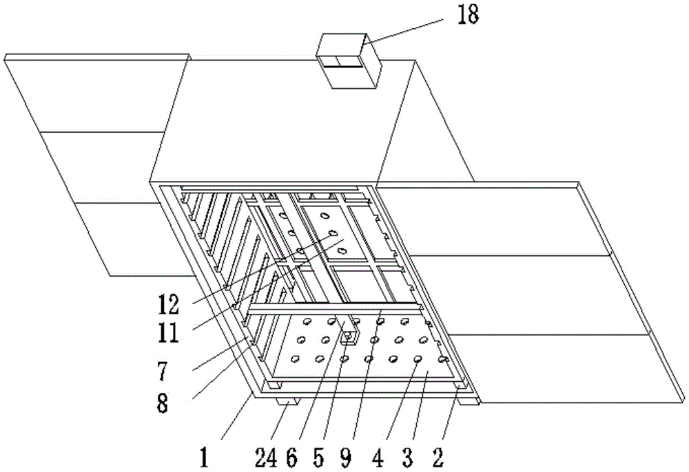
图1为本实用新型立体结构示意图;1 is a schematic diagram of the three-dimensional structure of the present utility model;
图2为本实用新型竖向线槽结构示意图;Fig. 2 is the structural schematic diagram of the vertical wire slot of the present utility model;
图3为本实用新型孔盖结构示意图;Fig. 3 is the structural schematic diagram of the hole cover of the present invention;
图4为本实用新型蛇形抽风管道结构示意图;Fig. 4 is the structure schematic diagram of the serpentine ventilation duct of the utility model;
图5为本实用新型送风箱内部结构示意图。FIG. 5 is a schematic diagram of the internal structure of the air supply box of the present invention.
图中:1、配电柜外壳;2、绝缘支撑块;3、开孔安装板;4、安装孔;5、螺栓;6、竖向安装板;7、凹槽安装板;8、滑动凹槽;9、横向安装板;10、安装框;11、隔离多孔板;12、通线孔;13、竖向线槽;14、线槽孔;15、横向线槽;16、孔盖;17、导线汇聚箱;18、顶部抽风扇;19、抽风管道;20、蛇形抽风管道;21、送风箱;22、送风电扇;23、隔尘网;24、支撑脚。In the figure: 1. Power distribution cabinet shell; 2. Insulation support block; 3. Opening mounting plate; 4. Mounting hole; 5. Bolt; 6. Vertical mounting plate; 7. Groove mounting plate; 8. Sliding recess Slot; 9. Horizontal mounting plate; 10. Mounting frame; 11. Isolation perforated plate; 12. Cable hole; 13. Vertical cable slot; 14. Cable slot hole; 15. Horizontal cable slot; 16. Hole cover; 17 , Wire convergence box; 18, top exhaust fan; 19, exhaust duct; 20, serpentine exhaust duct; 21, air supply box; 22, air supply fan; 23, dust filter; 24, support feet.
具体实施方式Detailed ways
下面将结合本实用新型实施例中的附图,对本实用新型实施例中的技术方案进行清楚、完整地描述,显然,所描述的实施例仅仅是本实用新型一部分实施例,而不是全部的实施例。The technical solutions in the embodiments of the present utility model will be clearly and completely described below with reference to the accompanying drawings in the embodiments of the present utility model. Obviously, the described embodiments are only a part of the embodiments of the present utility model, rather than all the implementations. example.
请参阅图1至图5,本实用新型提供一种技术方案:一种高压配电柜,包括配电柜外壳1、隔离多孔板11和竖向线槽13,配电柜外壳1的内底壁固定连接有绝缘支撑块2,绝缘支撑块2的上部固定连接有开孔安装板3,开孔安装板3的一侧开设有安装孔4,安装孔4的数量为若干个,开孔安装板3通过连接螺栓5螺纹连接有竖向安装板6,开孔安装板3的上部固定连接有凹槽安装板7,凹槽安装板7的一侧设置有滑动凹槽8,滑动凹槽8的数量为若干个,凹槽安装板7通过滑动凹槽8滑动连接有横向安装板9,通过开孔安装板3和凹槽安装板7的配合设置,在使用的过程中可以通过开孔安装板3一侧的安装孔4来进行竖向安装板6的安装,竖向安装板6可以用来安装配电柜内部需要安装的装置,由于安装孔4有若干个,所以竖向安装板6可以根据不同的情况来调节安装的位置,凹槽安装板7可以通过其一侧的滑动凹槽8来进行横向安装板9的安装,根据情况的不同横向安装板9可以随时调节安装的位置,从而起到了安装配电柜内部装置的作用,达到了使其能够根据情况的不同来调节配电柜内部装置安装位置的目的,横向安装板9的数量为若干个,配电柜外壳1的内壁固定连接有安装框10,安装框10的一侧固定连接有隔离多孔板11,隔离多孔板11的一侧开设有通线孔12,隔离多孔板11的一侧固定连接有竖向线槽13,通过安装框10、隔离多孔板11和竖向线槽13的配合设置,在使用的过程中可以通过安装框10来安装隔离多孔板11,通过隔离多孔板11一侧的通线孔12,可以将导线安装到竖向线槽13的内部,从而起到了安装导线的作用,达到了能够根据不同的情况来安装导线的目的,竖向线槽13的数量为两个,竖向线槽13的一侧开设有线槽孔14,竖向线槽13之间通过横向线槽15固定连接,竖向线槽13通过线槽孔14套接有孔盖16,通过孔盖16的设置,使该配电柜竖向线槽13一侧的线槽孔14在不需要使用时具备了能够封闭的效果,配电柜外壳1的内壁固定连接有导线汇聚箱17,配电柜外壳1的顶部固定连接有顶部抽风扇18,顶部抽风扇18的一侧固定连接有抽风管道19,抽风管道19的一侧固定连接有蛇形抽风管道20,通过蛇形抽风管道20的设置,在使用时可以将蛇形抽风管道20对准某个特别热的装置上来进行通风,从而达到了有效散热的目的,配电柜外壳1的一侧固定连接有送风箱21,送风箱21的内部固定连接有送风电扇22,送风箱21的一侧固定连接有隔尘网23,配电柜外壳1的底部固定连接有支撑脚24。Please refer to FIG. 1 to FIG. 5 , the present invention provides a technical solution: a high-voltage power distribution cabinet, comprising a power
该文中出现的电器元件均与外界的主控器及220V市电电连接,并且主控器可为计算机等起到控制的常规已知设备。The electrical components appearing in this article are all connected with the external main controller and 220V mains, and the main controller can be a conventional known device controlled by a computer or the like.
使用时,开孔安装板3可以通过其一侧的安装孔4来进行竖向安装板6的安装,竖向安装板6可以用来进行电器装置的安装,由于安装孔4有若干个,所以竖向安装板6可以根据不同的需求来调节竖向安装板6的安装位置,凹槽安装板7可以通过滑动凹槽8来进行横向安装板9的安装,横向安装板9可以来进行电器装置的放置,在进行导线安装时可以通过竖向线槽13和横向线槽15来进行安装,导线汇聚箱17可以将导线进行汇集,该配电箱在进行散热时可以通过将蛇形抽风管道20对准发热源,然后通过顶部抽风扇18来进行直接散热,送风电扇22起到输送空气的作用。When in use, the perforated mounting
本实用新型的工作原理及有益效果:该高压配电柜,通过蛇形抽风管道20的设置,在使用时可以将蛇形抽风管道20对准某个特别热的装置上来进行通风,从而达到了有效散热的目的,通过开孔安装板3和凹槽安装板7的配合设置,在使用的过程中可以通过开孔安装板3一侧的安装孔4来进行竖向安装板6的安装,竖向安装板6可以用来安装配电柜内部需要安装的装置,由于安装孔4有若干个,所以竖向安装板6可以根据不同的情况来调节安装的位置,凹槽安装板7可以通过其一侧的滑动凹槽8来进行横向安装板9的安装,根据情况的不同横向安装板9可以随时调节安装的位置,从而起到了安装配电柜内部装置的作用,达到了使其能够根据情况的不同来调节配电柜内部装置安装位置的目的,通过孔盖16的设置,使该配电柜竖向线槽13一侧的线槽孔14在不需要使用时具备了能够封闭的效果,通过安装框10、隔离多孔板11和竖向线槽13的配合设置,在使用的过程中可以通过安装框10来安装隔离多孔板11,通过隔离多孔板11一侧的通线孔12,可以将导线安装到竖向线槽13的内部,从而起到了安装导线的作用,达到了能够根据不同的情况来安装导线的目的。The working principle and beneficial effects of the present utility model: the high-voltage power distribution cabinet, through the arrangement of the
以上所述,仅为本实用新型较佳的具体实施方式,但本实用新型的保护范围并不局限于此,任何熟悉本技术领域的技术人员在本实用新型揭露的技术范围内,根据本实用新型的技术方案及其实用新型构思加以等同替换或改变,都应涵盖在本实用新型的保护范围之内。The above description is only a preferred embodiment of the present invention, but the protection scope of the present invention is not limited to this. Equivalent replacement or modification of the new technical solution and its utility model concept shall be included within the protection scope of the present utility model.
Claims (6)
Priority Applications (1)
| Application Number | Priority Date | Filing Date | Title |
|---|---|---|---|
| CN201922297950.6U CN210926725U (en) | 2019-12-19 | 2019-12-19 | High-voltage power distribution cabinet |
Applications Claiming Priority (1)
| Application Number | Priority Date | Filing Date | Title |
|---|---|---|---|
| CN201922297950.6U CN210926725U (en) | 2019-12-19 | 2019-12-19 | High-voltage power distribution cabinet |
Publications (1)
| Publication Number | Publication Date |
|---|---|
| CN210926725U true CN210926725U (en) | 2020-07-03 |
Family
ID=71344861
Family Applications (1)
| Application Number | Title | Priority Date | Filing Date |
|---|---|---|---|
| CN201922297950.6U Expired - Fee Related CN210926725U (en) | 2019-12-19 | 2019-12-19 | High-voltage power distribution cabinet |
Country Status (1)
| Country | Link |
|---|---|
| CN (1) | CN210926725U (en) |
Cited By (3)
| Publication number | Priority date | Publication date | Assignee | Title |
|---|---|---|---|---|
| CN112235989A (en) * | 2020-10-03 | 2021-01-15 | 顾康杰 | Mixed pressure boost conveyor of industrial chemicals |
| US11619055B1 (en) | 2022-06-22 | 2023-04-04 | James M. Kunert | Outdoor electrical cabinet and method of construction |
| USD990562S1 (en) | 2022-04-15 | 2023-06-27 | James M. Kunert | Combination electrical cabinet and sign |
-
2019
- 2019-12-19 CN CN201922297950.6U patent/CN210926725U/en not_active Expired - Fee Related
Cited By (3)
| Publication number | Priority date | Publication date | Assignee | Title |
|---|---|---|---|---|
| CN112235989A (en) * | 2020-10-03 | 2021-01-15 | 顾康杰 | Mixed pressure boost conveyor of industrial chemicals |
| USD990562S1 (en) | 2022-04-15 | 2023-06-27 | James M. Kunert | Combination electrical cabinet and sign |
| US11619055B1 (en) | 2022-06-22 | 2023-04-04 | James M. Kunert | Outdoor electrical cabinet and method of construction |
Similar Documents
| Publication | Publication Date | Title |
|---|---|---|
| CN207868675U (en) | A kind of insulated metal ring main unit | |
| CN208316081U (en) | A kind of energy-saving high and low voltage switchgear | |
| CN207967713U (en) | A kind of intelligent heat dissipation formula middle-placed switch cabinet | |
| CN206516446U (en) | A miniature safety electronic transformer | |
| CN211266114U (en) | An outdoor low-voltage integrated distribution box | |
| CN205104818U (en) | Metal armor puts aside formula switchgear with temperature control system | |
| CN208209296U (en) | A kind of active power filtering cabinet with multiple pluggable modules | |
| CN214255201U (en) | Cubical switchboard for photovoltaic little electric wire netting | |
| CN204424732U (en) | A kind of high voltage power distributing cabinet changing current transformer position | |
| CN112152098A (en) | A new type of integrated combined low-voltage cabinet | |
| CN203260920U (en) | High-voltage switchgear capable of cooling and dehumidifying | |
| CN207559567U (en) | A kind of Low-voltage Line Loss intelligent compensation terminal | |
| CN217159060U (en) | Electric power engineering heat dissipation power equipment | |
| CN206302058U (en) | A kind of practical low voltage drawing-out switching carbinet | |
| CN207339042U (en) | Intelligent amorphous alloy transformer platform on 10kV integration columns | |
| CN205670639U (en) | A kind of novel intelligent JP power distribution cabinet | |
| CN202888671U (en) | Power distribution cabinet provided with monitoring devices | |
| CN223856601U (en) | Wireless temperature measurement collection system in cubical switchboard | |
| CN216981241U (en) | Socket switch box | |
| CN207530393U (en) | A kind of GGD type low-voltage alternating-current power distribution cabinets for facilitating multiple breaker installations | |
| CN214755133U (en) | A withdrawable switch cabinet for easy temperature control | |
| CN105207231A (en) | Draw-out type dynamic reactive compensation device | |
| CN221328359U (en) | Multifunctional power supply maintenance box capable of being embedded and hung | |
| CN206673423U (en) | A kind of American Unit Substation of perfect heat-dissipating | |
| CN205753141U (en) | A kind of electrical network distribution box |
Legal Events
| Date | Code | Title | Description |
|---|---|---|---|
| GR01 | Patent grant | ||
| GR01 | Patent grant | ||
| CF01 | Termination of patent right due to non-payment of annual fee | ||
| CF01 | Termination of patent right due to non-payment of annual fee |
Granted publication date: 20200703 |