CN210921438U - A waste heat recovery device for catalytic combustion exhaust gas treatment - Google Patents
A waste heat recovery device for catalytic combustion exhaust gas treatment Download PDFInfo
- Publication number
- CN210921438U CN210921438U CN201921933763.6U CN201921933763U CN210921438U CN 210921438 U CN210921438 U CN 210921438U CN 201921933763 U CN201921933763 U CN 201921933763U CN 210921438 U CN210921438 U CN 210921438U
- Authority
- CN
- China
- Prior art keywords
- box body
- exhaust gas
- frame
- heat recovery
- water pipe
- Prior art date
- Legal status (The legal status is an assumption and is not a legal conclusion. Google has not performed a legal analysis and makes no representation as to the accuracy of the status listed.)
- Expired - Fee Related
Links
- 239000007789 gas Substances 0.000 title claims abstract description 55
- 238000011084 recovery Methods 0.000 title claims abstract description 19
- 238000007084 catalytic combustion reaction Methods 0.000 title claims abstract description 18
- 239000002918 waste heat Substances 0.000 title claims abstract description 18
- XLYOFNOQVPJJNP-UHFFFAOYSA-N water Substances O XLYOFNOQVPJJNP-UHFFFAOYSA-N 0.000 claims abstract description 66
- 239000002912 waste gas Substances 0.000 claims abstract description 6
- OKTJSMMVPCPJKN-UHFFFAOYSA-N Carbon Chemical compound [C] OKTJSMMVPCPJKN-UHFFFAOYSA-N 0.000 claims description 33
- 239000007788 liquid Substances 0.000 claims description 18
- 238000001035 drying Methods 0.000 claims description 16
- 230000003472 neutralizing effect Effects 0.000 claims description 15
- 238000005192 partition Methods 0.000 claims description 13
- 238000010438 heat treatment Methods 0.000 claims description 7
- 230000002265 prevention Effects 0.000 claims description 5
- 230000005540 biological transmission Effects 0.000 claims description 3
- 239000003822 epoxy resin Substances 0.000 claims description 3
- 239000003292 glue Substances 0.000 claims description 3
- 238000009413 insulation Methods 0.000 claims description 3
- 229920000647 polyepoxide Polymers 0.000 claims description 3
- 238000002485 combustion reaction Methods 0.000 abstract description 4
- 238000004064 recycling Methods 0.000 abstract description 3
- 239000012855 volatile organic compound Substances 0.000 description 6
- 238000000034 method Methods 0.000 description 4
- 238000010586 diagram Methods 0.000 description 3
- 238000009776 industrial production Methods 0.000 description 3
- UGFAIRIUMAVXCW-UHFFFAOYSA-N Carbon monoxide Chemical compound [O+]#[C-] UGFAIRIUMAVXCW-UHFFFAOYSA-N 0.000 description 2
- 230000000694 effects Effects 0.000 description 2
- 239000003546 flue gas Substances 0.000 description 2
- 239000002440 industrial waste Substances 0.000 description 2
- 238000003915 air pollution Methods 0.000 description 1
- 230000009286 beneficial effect Effects 0.000 description 1
- 229910052799 carbon Inorganic materials 0.000 description 1
- 238000005516 engineering process Methods 0.000 description 1
- 239000012535 impurity Substances 0.000 description 1
Images


Classifications
-
- Y—GENERAL TAGGING OF NEW TECHNOLOGICAL DEVELOPMENTS; GENERAL TAGGING OF CROSS-SECTIONAL TECHNOLOGIES SPANNING OVER SEVERAL SECTIONS OF THE IPC; TECHNICAL SUBJECTS COVERED BY FORMER USPC CROSS-REFERENCE ART COLLECTIONS [XRACs] AND DIGESTS
- Y02—TECHNOLOGIES OR APPLICATIONS FOR MITIGATION OR ADAPTATION AGAINST CLIMATE CHANGE
- Y02E—REDUCTION OF GREENHOUSE GAS [GHG] EMISSIONS, RELATED TO ENERGY GENERATION, TRANSMISSION OR DISTRIBUTION
- Y02E20/00—Combustion technologies with mitigation potential
- Y02E20/30—Technologies for a more efficient combustion or heat usage
Landscapes
- Treating Waste Gases (AREA)
Abstract
本实用新型涉及废气处理技术领域,公开了一种用于催化燃烧废气处理的余热回收装置,为解决现有设备对废气余热回收的不充分的问题,所述箱体的一侧设置有出气口,且箱体的另一侧设置有进气口,所述箱体的前表面一侧设置有控制面板,且箱体的下表面均匀设置有固定座,所述箱体的前表面位于控制面板的另一侧位置处设置有气体监测仪。本实用新型设置有循环水管,通过使得水管曲折放置从而能够增加水管的长度,进一步的能够使得燃烧废气进入箱体内部的时候与循环水管接触,采用电机带动旋转的循环水管能够使得水管充分的与热废气接触,使得热量传递到循环水管内部运送的水中,从而产生热水回收利用。
The utility model relates to the technical field of waste gas treatment, and discloses a waste heat recovery device for catalytic combustion waste gas treatment. In order to solve the problem of insufficient waste heat recovery of waste gas by existing equipment, one side of the box body is provided with an air outlet , and the other side of the box body is provided with an air inlet, the front surface of the box body is provided with a control panel, and the lower surface of the box body is evenly provided with a fixed seat, and the front surface of the box body is located on the control panel. A gas monitor is installed on the other side of the . The utility model is provided with a circulating water pipe, and the length of the water pipe can be increased by placing the water pipe in a zigzag manner, and further, the combustion exhaust gas can be brought into contact with the circulating water pipe when entering the inside of the box, and the circulating water pipe driven by a motor can make the water pipe fully and The hot exhaust gas contacts, so that the heat is transferred to the water transported inside the circulating water pipe, thereby producing hot water for recycling.
Description
技术领域technical field
本实用新型涉及废气处理技术领域,具体是一种用于催化燃烧废气处理的余热回收装置。The utility model relates to the technical field of waste gas treatment, in particular to a waste heat recovery device for catalytic combustion waste gas treatment.
背景技术Background technique
在工业生产中会产生大量的工业废气,这些工业废气通常温度都很高,例如工业生产中使用的锅炉,它们的烟气温度一般在两百至三百度,有的甚至更高,这些催化燃烧废气排散到大气中的高温烟气所含热量不加以利用是非常可惜的查找 在工业生产过程中往往会产生一些可燃废气,这些可燃废气排放到大气中将产生污染。特别是挥发性有机化合物(VOCs)排放至大气中将对人体健康产生影响,我国VOCs排放总量为2503万吨,其中工业源VOCs排放最多,占总量的43%,2015年8月颁布的《中华人民共和国大气污染防治法》新增四个VOCs污染控制条款,高温焚烧是VOCs治理的重要方法。In industrial production, a large amount of industrial waste gas will be produced. These industrial waste gases are usually very high in temperature. For example, boilers used in industrial production, their flue gas temperature is generally 200 to 300 degrees Celsius, and some are even higher. These catalytic combustion It is a pity that the heat contained in the high-temperature flue gas discharged into the atmosphere is not utilized. In the industrial production process, some combustible exhaust gas is often generated, and these combustible exhaust gases are discharged into the atmosphere and will cause pollution. In particular, the emission of volatile organic compounds (VOCs) into the atmosphere will have an impact on human health. The total emission of VOCs in my country is 25.03 million tons, of which industrial VOCs emission is the largest, accounting for 43% of the total. The Law of the People's Republic of China on the Prevention and Control of Air Pollution adds four new VOCs pollution control clauses, and high-temperature incineration is an important method for VOCs control.
但是现有的热回收设备通常对废气中的余热回收不充分,另外排放的废气中依然有很多未处理的有害气体。因此,本领域技术人员提供了一种用于催化燃烧废气处理的余热回收装置,以解决上述背景技术中提出的问题。However, the existing heat recovery equipment usually does not sufficiently recover the waste heat in the exhaust gas, and there are still many untreated harmful gases in the exhaust gas discharged. Therefore, those skilled in the art provide a waste heat recovery device for catalytic combustion exhaust gas treatment to solve the problems raised in the above background art.
实用新型内容Utility model content
本实用新型的目的在于提供一种用于催化燃烧废气处理的余热回收装置,以解决上述背景技术中提出的问题。The purpose of the present invention is to provide a waste heat recovery device for catalytic combustion exhaust gas treatment, so as to solve the problems raised in the above background technology.
为实现上述目的,本实用新型提供如下技术方案:To achieve the above object, the utility model provides the following technical solutions:
一种用于催化燃烧废气处理的余热回收装置,包括箱体,所述箱体的一侧设置有出气口,且箱体的另一侧设置有进气口,所述箱体的前表面一侧设置有控制面板,且箱体的下表面均匀设置有固定座,所述箱体的前表面位于控制面板的另一侧位置处设置有气体监测仪,所述箱体的一侧位于出气口的下方设置有出水管,且箱体的内部设置有中隔板,所述箱体的一侧位于进气口的下方位置处设置有进水管,且箱体的内部一侧设置有循环水管,所述循环水管的一端对应进水管的位置处通过转动轴A与箱体转动连接,且循环水管的另一端通过转动轴B与中隔板转动连接,所述中隔板的一侧位于转动轴B的上方位置处设置有电机,且中隔板的另一侧设置有出气管,所述出气管的下端设置有防倒吸箱,所述防倒吸箱的下方设置有水箱,且防倒吸箱的一侧位于水箱的上表面设置有加热网,所述水箱的内部设置有中和液,所述箱体的内部位于转动轴B的一侧设置有连接管,且箱体的内侧表面设置有保温层,所述电机的传动端设置有主动齿轮,所述循环水管对应主动齿轮的位置处设置有从动齿轮。A waste heat recovery device for catalytic combustion exhaust gas treatment includes a box body, one side of the box body is provided with an air outlet, and the other side of the box body is provided with an air inlet port, the front surface of the box body is a The side is provided with a control panel, and the lower surface of the box body is evenly provided with a fixed seat, the front surface of the box body is located on the other side of the control panel, and a gas monitor is provided, and one side of the box body is located at the air outlet A water outlet pipe is arranged at the bottom of the box body, and a middle partition plate is arranged inside the box body, a water inlet pipe is arranged on one side of the box body at the position below the air inlet, and a circulating water pipe is arranged on the inner side of the box body. One end of the circulating water pipe is rotatably connected to the box through the rotation axis A at the position of the water inlet pipe, and the other end of the circulating water pipe is rotatably connected to the middle partition plate through the rotation axis B, and one side of the middle partition plate is located on the rotation axis. A motor is arranged at the upper position of B, and an air outlet pipe is arranged on the other side of the middle partition plate. The lower end of the air outlet pipe is provided with an anti-suction box, and a water tank is arranged below the anti-suction box, and the anti-suction box is arranged below. One side of the suction box is located on the upper surface of the water tank and is provided with a heating net, the interior of the water tank is provided with neutralizing liquid, the interior of the box body is located on the side of the rotating shaft B, and a connecting pipe is provided, and the inner surface of the box body is provided with a connecting pipe. An insulating layer is provided, a driving gear is provided at the transmission end of the motor, and a driven gear is provided at the position of the circulating water pipe corresponding to the driving gear.
作为本实用新型再进一步的方案:所述出气口包括固定架,所述固定架的内侧均匀设置有挡板,且固定架的内侧位于挡板之间设置有滑道,所述固定架的一侧设置有框架,所述框架的表面均匀设置有卡扣,且框架的内部设置有过滤网装置。As a further solution of the present invention: the air outlet includes a fixing frame, the inner side of the fixing frame is evenly provided with baffles, and the inner side of the fixing frame is provided with a slideway between the baffles, one of the fixing frame is The side is provided with a frame, the surface of the frame is evenly provided with snaps, and the interior of the frame is provided with a filter screen device.
作为本实用新型再进一步的方案:所述卡扣与滑道相适配,所述框架的外径与固定架的内径长度一致,所述固定架的一侧与箱体固定连接。As a further solution of the present invention, the buckle is adapted to the slideway, the outer diameter of the frame is consistent with the inner diameter of the fixing frame, and one side of the fixing frame is fixedly connected to the box body.
作为本实用新型再进一步的方案:所述过滤网装置包括活性碳网,所述活性碳网的后侧设置有干燥网,所述干燥网的后侧设置有筛网。As a further solution of the present invention, the filter screen device includes an activated carbon screen, a drying screen is arranged on the rear side of the activated carbon screen, and a screen is arranged on the rear side of the drying screen.
作为本实用新型再进一步的方案:所述筛网、干燥网、活性碳网的外径与框架的内径一致,且筛网、干燥网、活性碳网通过环氧树脂胶与框架固定连接。As a further scheme of the present invention, the outer diameter of the screen, drying screen and activated carbon screen is consistent with the inner diameter of the frame, and the screen, drying screen and activated carbon screen are fixedly connected to the frame through epoxy resin glue.
作为本实用新型再进一步的方案:所述主动齿轮与从动齿轮啮合连接,所述防倒吸箱的下端设置有浸入中和液中的气管,所述中和液的液面高度位于水箱的三分之二位置处。As a further solution of the present invention, the driving gear and the driven gear are meshed and connected, the lower end of the anti-suckback box is provided with an air pipe immersed in the neutralizing liquid, and the liquid level of the neutralizing liquid is located at the height of the water tank. two-thirds of the way.
与现有技术相比,本实用新型的有益效果是:Compared with the prior art, the beneficial effects of the present utility model are:
本实用新型设置有循环水管,通过水管在箱体中曲折放置从而能够增加水管的长度,进一步的能够使得燃烧废气进入箱体内部的时候与循环水管接触,采用电机带动旋转的循环水管能够使得水管充分的与热废气接触,使得热量传递到循环水管内部运送的水中,从而产生热水回收利用,设置有中和液,中和液能够中和废气中的有害气体,有效的降低有害气体的排放,设置有加热网,能够将未充分燃烧的碳分子再次点燃使得燃烧充分,避免污染环境,设置有过滤网装置能够有效的保证排出的气体干燥、不含杂质、无异味。The utility model is provided with a circulating water pipe, and the length of the water pipe can be increased by placing the water pipe in a zigzag manner in the box body, and further, when the combustion exhaust gas enters the inside of the box body, it can contact the circulating water pipe, and the circulating water pipe driven by a motor can make the water pipe It is fully contacted with the hot exhaust gas, so that the heat is transferred to the water transported inside the circulating water pipe, thereby producing hot water for recycling. A neutralizing liquid is provided, which can neutralize the harmful gases in the exhaust gas and effectively reduce the emission of harmful gases. , It is equipped with a heating net, which can re-ignite the insufficiently burned carbon molecules to make the combustion fully and avoid polluting the environment.
附图说明Description of drawings
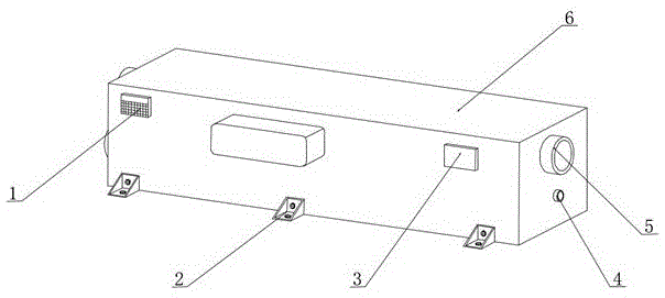
图1为一种用于催化燃烧废气处理的余热回收装置的结构示意图;1 is a schematic structural diagram of a waste heat recovery device for catalytic combustion exhaust gas treatment;
图2为一种用于催化燃烧废气处理的余热回收装置中内部的正视图;2 is a front view of the interior of a waste heat recovery device for catalytic combustion exhaust gas treatment;
图3为一种用于催化燃烧废气处理的余热回收装置中出气口的结构示意图;3 is a schematic structural diagram of an air outlet in a waste heat recovery device used for catalytic combustion exhaust gas treatment;
图4为一种用于催化燃烧废气处理的余热回收装置中过滤网装置的结构示意图。FIG. 4 is a schematic structural diagram of a filter screen device in a waste heat recovery device used for catalytic combustion exhaust gas treatment.
图中:1、控制面板;2、固定座;3、气体监测仪;4、出水管;5、出气口;51、卡扣;52、框架;53、过滤网装置;531、筛网;532、干燥网;533、活性碳网;54、滑道;55、挡板;56、固定架;6、箱体;7、进气口;8、进水管;9、转动轴A;10、循环水管;11、主动齿轮;12、从动齿轮;13、转动轴B;14、中和液;15、防倒吸箱;16、加热网;17、水箱;18、连接管;19、出气管;20、中隔板;21、电机;22、保温层。In the figure: 1. Control panel; 2. Fixed seat; 3. Gas monitor; 4. Water outlet; 5. Air outlet; 51. Buckle; 52. Frame; 53. Filter device; 531, Screen mesh; 532 , drying net; 533, activated carbon net; 54, slideway; 55, baffle; 56, fixing frame; 6, box body; 7, air inlet; 8, water inlet pipe; 9, rotating shaft A; 10, circulation Water pipe; 11, driving gear; 12, driven gear; 13, rotating shaft B; 14, neutralizing liquid; 15, anti-suck back box; 16, heating net; 17, water tank; 18, connecting pipe; 19, air outlet pipe ; 20, the middle partition; 21, the motor; 22, the insulation layer.
具体实施方式Detailed ways
请参阅图1~4,本实用新型实施例中,一种用于催化燃烧废气处理的余热回收装置,包括箱体6,箱体6的一侧设置有出气口5,出气口5包括固定架56,固定架56的内侧均匀设置有挡板55,且固定架56的内侧位于挡板55之间设置有滑道54,固定架56的一侧设置有框架52,框架52的表面均匀设置有卡扣51,且框架52的内部设置有过滤网装置53,过滤网装置53包括活性碳网533,活性碳网533的后侧设置有干燥网532,干燥网532的后侧设置有筛网531,干燥网532能够将废气中的水汽吸附,活性碳网533能够有效的将废气中的异味吸附,避免异味散至环境中,筛网531能够将废气中的杂质过滤,避免散至环境中。Referring to FIGS. 1 to 4 , in an embodiment of the present invention, a waste heat recovery device for catalytic combustion exhaust gas treatment includes a
筛网531、干燥网532、活性碳网533的外径与框架52的内径一致,且筛网531、干燥网532、活性碳网533通过环氧树脂胶与框架52固定连接,环氧树脂胶固定的筛网531、干燥网532、活性碳网533能够在高温环境下不会脱胶。The outer diameter of the
卡扣51通过滑道54滑进固定架56的内部,进一步的转动框架52使得挡板55能够挡住卡扣51,从而达到固定框架52的效果。The
卡扣51与滑道54相适配,框架52的外径与固定架56的内径长度一致,固定架56的一侧与箱体6固定连接,框架52通过在固定架56的内部转动,从而使得卡扣51转动至挡板55的后方,此种固定方式使得框架52便于拆卸更换。The
箱体6的另一侧设置有进气口7,箱体6的前表面一侧设置有控制面板1,且箱体6的下表面均匀设置有固定座2,箱体6的前表面位于控制面板1的另一侧位置处设置有气体监测仪3,箱体6的一侧位于出气口5的下方设置有出水管4,且箱体6的内部设置有中隔板20,箱体6的一侧位于进气口7的下方位置处设置有进水管8,且箱体6的内部一侧设置有循环水管10,循环水管10的一端对应进水管8的位置处通过转动轴A9与箱体6转动连接,且循环水管10的另一端通过转动轴B13与中隔板20转动连接,中隔板20的一侧位于转动轴B13的上方位置处设置有电机21,且中隔板20的另一侧设置有出气管19,出气管19的下端设置有防倒吸箱15,防倒吸箱15的下方设置有水箱17,且防倒吸箱15的一侧位于水箱17的上表面设置有加热网16,水箱17的内部设置有中和液14,主动齿轮11与从动齿轮12啮合连接,防倒吸箱15的下端设置有浸入中和液14中的气管,中和液14的液面高度位于水箱17的三分之二位置处,防倒吸箱15的设置能够有效的避免因为温度导致的水倒吸现象,中和液14能够有效的中和废气中的有害气体,做到了对废气中有害气体的处理。The other side of the
箱体6的内部位于转动轴B13的一侧设置有连接管18,且箱体6的内侧表面设置有保温层22,电机21的传动端设置有主动齿轮11,循环水管10对应主动齿轮11的位置处设置有从动齿轮12。The inside of the
本实用新型的工作原理是:首先燃烧废气通过进气口7进入箱体6的内部,外界水源通过进水管8进入循环水管10,通过控制面板1控制电机21的转动,进一步的电机21带动主动齿轮11的转动,从而主动齿轮11通过从动齿轮12带动循环水管10的转动,带有热量的废气与循环水管10充分接触,从而热量能够通过循环水管10中的水流通过出水管4带出,从而对暖水回收利用,废气通过出气管19进入防倒吸箱15进一步的通到中和液14中,中和液14能够对废气中的有害气体中和,避免有害气体排向环境中,尾气通过中和液14后传向加热网16,经过加热网16的加热对废气中未燃烧充分的进行二次燃烧,避免废气排出污染环境,卡扣51通过滑道54滑进固定架56的内部,进一步的转动框架52使得挡板55能够挡住卡扣51,从而达到固定框架52的效果,框架52通过在固定架56的内部转动,从而使得卡扣51转动至挡板55的后方,此种固定方式使得框架52便于拆卸更换,干燥网532能够将废气中的水汽吸附,活性碳网533能够有效的将废气中的异味吸附,避免异味散至环境中,筛网531能够将废气中的杂质过滤,避免散至环境中。The working principle of the utility model is as follows: firstly, the combustion exhaust gas enters the interior of the
以上所述的,仅为本实用新型较佳的具体实施方式,但本实用新型的保护范围并不局限于此,任何熟悉本技术领域的技术人员在本实用新型揭露的技术范围内,根据本实用新型的技术方案及其实用新型构思加以等同替换或改变,都应涵盖在本实用新型的保护范围之内。The above are only the preferred specific embodiments of the present invention, but the protection scope of the present invention is not limited to this. The technical solution of the utility model and its utility model concept are equivalently replaced or changed, and should be covered within the protection scope of the present utility model.
Claims (6)
Priority Applications (1)
| Application Number | Priority Date | Filing Date | Title |
|---|---|---|---|
| CN201921933763.6U CN210921438U (en) | 2019-11-11 | 2019-11-11 | A waste heat recovery device for catalytic combustion exhaust gas treatment |
Applications Claiming Priority (1)
| Application Number | Priority Date | Filing Date | Title |
|---|---|---|---|
| CN201921933763.6U CN210921438U (en) | 2019-11-11 | 2019-11-11 | A waste heat recovery device for catalytic combustion exhaust gas treatment |
Publications (1)
| Publication Number | Publication Date |
|---|---|
| CN210921438U true CN210921438U (en) | 2020-07-03 |
Family
ID=71364812
Family Applications (1)
| Application Number | Title | Priority Date | Filing Date |
|---|---|---|---|
| CN201921933763.6U Expired - Fee Related CN210921438U (en) | 2019-11-11 | 2019-11-11 | A waste heat recovery device for catalytic combustion exhaust gas treatment |
Country Status (1)
| Country | Link |
|---|---|
| CN (1) | CN210921438U (en) |
Cited By (1)
| Publication number | Priority date | Publication date | Assignee | Title |
|---|---|---|---|---|
| CN112283580A (en) * | 2020-10-21 | 2021-01-29 | 普布旦增 | Storage device with temperature control function for recycling waste gas and fuel gas |
-
2019
- 2019-11-11 CN CN201921933763.6U patent/CN210921438U/en not_active Expired - Fee Related
Cited By (1)
| Publication number | Priority date | Publication date | Assignee | Title |
|---|---|---|---|---|
| CN112283580A (en) * | 2020-10-21 | 2021-01-29 | 普布旦增 | Storage device with temperature control function for recycling waste gas and fuel gas |
Similar Documents
| Publication | Publication Date | Title |
|---|---|---|
| CN112973317B (en) | A kind of exhaust gas treatment equipment for chemical production | |
| CN107398260A (en) | A kind of regenerating unit and its method for being used to adsorb the activated carbon of organic exhaust gas | |
| CN203484405U (en) | Multi-heat source shaftless interval-heating thermal desorption device for repairing soil polluted by organic matter | |
| CN108325278A (en) | A kind of brick field drying chamber tail gas energy conservation and environmental protection processing equipment | |
| CN105347654B (en) | The furnace drying method and its dryer of a kind of sludge | |
| CN115626754A (en) | Hot gas circulation type sludge heat pump drying device | |
| CN213853900U (en) | An integrated VOC waste gas treatment device | |
| CN114570756B (en) | Waste heat recovery utilizes device for soil thermal remediation | |
| CN221045762U (en) | Be used for VOCs waste gas to administer device | |
| CN209828663U (en) | An activated carbon adsorption device for treating waste oil fume | |
| CN115341351B (en) | Cloth steaming fixation equipment | |
| CN216073954U (en) | Flange safe heat treatment natural gas furnace device | |
| CN217287764U (en) | A catalytic combustion exhaust gas treatment device | |
| CN216770217U (en) | Waste gas recovery device for metal waste roasting furnace | |
| CN205535860U (en) | Energy -saving dangerous waste incineration system | |
| CN211803041U (en) | A green and recyclable device for treating heavy metal soil pollution | |
| CN222317002U (en) | Environment-friendly garbage incinerator | |
| CN221451954U (en) | Decoloring device for petroleum methyl naphthalene production | |
| CN217057547U (en) | A waste heat recovery and utilization device for solid waste treatment | |
| CN222362077U (en) | A controllable air inlet system for a biomass gas stove | |
| CN221403100U (en) | Exhaust treatment device for adhesive production | |
| CN218442334U (en) | Catalytic combustion equipment with heat recovery function | |
| CN222539976U (en) | A unloading device for asphalt processing | |
| CN218366985U (en) | Printing baking device convenient for waste gas removal for glass processing | |
| CN222989835U (en) | Hazardous waste landfill leachate treatment equipment |
Legal Events
| Date | Code | Title | Description |
|---|---|---|---|
| GR01 | Patent grant | ||
| GR01 | Patent grant | ||
| CF01 | Termination of patent right due to non-payment of annual fee | ||
| CF01 | Termination of patent right due to non-payment of annual fee |
Granted publication date: 20200703 |