CN210920195U - Sealing structure with automatic compensation property - Google Patents
Sealing structure with automatic compensation property Download PDFInfo
- Publication number
- CN210920195U CN210920195U CN201922032925.5U CN201922032925U CN210920195U CN 210920195 U CN210920195 U CN 210920195U CN 201922032925 U CN201922032925 U CN 201922032925U CN 210920195 U CN210920195 U CN 210920195U
- Authority
- CN
- China
- Prior art keywords
- sealing
- sealing ring
- ring
- valve body
- conical surface
- Prior art date
- Legal status (The legal status is an assumption and is not a legal conclusion. Google has not performed a legal analysis and makes no representation as to the accuracy of the status listed.)
- Active
Links
Images


Landscapes
- Taps Or Cocks (AREA)
Abstract
本实用新型公开了一种具有自动补偿性质的密封结构,涉及密封结构技术领域,包括阀体,所述阀体内部的中间位置处设置有阀球,所述阀球的一侧与阀体的连接位置处设置有密封环,所述密封环的一侧设置有弹簧垫,所述密封环包括锥形面和凸起环。本实用新型通过设置锥形面,将密封环设置成锥形的配合形式,加大密封性,提高了密封作用,由于锥形面的可调节性质,使得阀体在该处产生泄漏点后,具备自动调节的功能,使其再次密封提高了设备的密封性,降低了工作难度。
The utility model discloses a sealing structure with automatic compensation properties, which relates to the technical field of sealing structures, comprising a valve body, a valve ball is arranged at a middle position inside the valve body, and one side of the valve ball is connected with the valve body. A sealing ring is arranged at the connection position, a spring washer is arranged on one side of the sealing ring, and the sealing ring includes a conical surface and a raised ring. By setting the conical surface, the utility model sets the sealing ring into a conical matching form, which increases the sealing performance and improves the sealing effect. With the function of automatic adjustment, it can be sealed again, which improves the sealing performance of the equipment and reduces the difficulty of work.
Description
技术领域technical field
本实用新型涉及密封结构技术领域,具体为一种具有自动补偿性质的密封结构。The utility model relates to the technical field of sealing structures, in particular to a sealing structure with automatic compensation properties.
背景技术Background technique
密封是防止气体、液体或者固体的泄漏与组织外部颗粒、流体进入密闭空间或管道系统的功用,能起密封作用的零部件称为密封件,较为复杂的密封连接称之为密封结构或密封装置,阀体通产采用密封环进行密封,密封环密封就是在两个互相配合的一个表面上开一个槽(根据密封环形状开槽),把密封圈置入里面,起到密封的作用,密封环密封用途非常广泛,按密封环形状分有很多种,最基本和常见的有0型密封环、U型密封环和Y型密封环,密封环的材料有金属的塑料的和橡胶制品,其中阀体中密封环使用次数最多,其目的是为了防止流动的介质从上阀座和下阀座相接触处的缝隙泄漏。Sealing is the function of preventing the leakage of gas, liquid or solid and the entry of particles and fluids outside the tissue into the closed space or pipeline system. The parts that can play a sealing role are called seals, and the more complex sealing connections are called sealing structures or sealing devices. , The valve body is generally sealed with a sealing ring. The sealing ring sealing is to open a groove on one surface of the two mating surfaces (slotting according to the shape of the sealing ring), and put the sealing ring inside to play a sealing role. Ring seals are widely used, and there are many types according to the shape of the seal ring. The most basic and common ones are 0-type sealing ring, U-type sealing ring and Y-type sealing ring. The material of the sealing ring is metal, plastic and rubber products, among which The sealing ring in the valve body is used most times, and its purpose is to prevent the flowing medium from leaking from the gap where the upper valve seat and the lower valve seat meet.
现有的密封结构通常为平面密封,密封面有限,密封效果不好,且平面密封环结构不具有可调节性质,当该处产生泄漏后,不具备自动调节功能,提高了工作难度。The existing sealing structure is usually a flat seal, the sealing surface is limited, the sealing effect is not good, and the flat sealing ring structure has no adjustable property.
发明内容SUMMARY OF THE INVENTION
本实用新型的目的在于为了解决现有的密封结构通常为平面密封,密封面有限,密封效果不好,且平面密封环结构不具有可调节性质,当该处产生泄漏后,不具备自动调节功能,提高了工作难度的问题,提供一种具有自动补偿性质的密封结构。The purpose of the present utility model is to solve the problem that the existing sealing structure is usually a flat seal, the sealing surface is limited, the sealing effect is not good, and the flat sealing ring structure does not have the adjustable property, and does not have the automatic adjustment function when leakage occurs at the place. , the problem of working difficulty is improved, and a sealing structure with automatic compensation property is provided.
为实现上述目的,本实用新型提供如下技术方案:一种具有自动补偿性质的密封结构,包括阀体,所述阀体内部的中间位置处设置有阀球,所述阀球的一侧与阀体的连接位置处设置有密封环,所述密封环的一侧设置有弹簧垫,所述密封环包括锥形面和凸起环。In order to achieve the above purpose, the present invention provides the following technical solutions: a sealing structure with automatic compensation properties, comprising a valve body, a valve ball is arranged at a middle position inside the valve body, and one side of the valve ball is connected to the valve body. A sealing ring is arranged at the connection position of the body, a spring washer is arranged on one side of the sealing ring, and the sealing ring includes a conical surface and a raised ring.
优选地,所述密封环和弹簧垫皆为圆形结构,所述密封环的顶部为凸起环,所述密封环的底部为锥形面。Preferably, both the sealing ring and the spring washer are circular structures, the top of the sealing ring is a raised ring, and the bottom of the sealing ring is a conical surface.
优选地,所述锥形面向上的倾斜角度为30°。Preferably, the upward inclination angle of the tapered surface is 30°.
优选地,所述密封环为四氟材质构成。Preferably, the sealing ring is made of tetrafluoro material.
与现有技术相比,本实用新型的有益效果是:Compared with the prior art, the beneficial effects of the present utility model are:
1、本实用新型通过设置锥形面,将密封环设置成锥形的配合形式,加大密封性,提高了密封作用;1. The utility model sets the sealing ring into a conical matching form by setting the conical surface, which increases the sealing performance and improves the sealing effect;
2、由于锥形面的可调节性质,使得阀体在该处产生泄漏点后,具备自动调节的功能,使其再次密封提高了设备的密封性,降低了工作难度。2. Due to the adjustable nature of the conical surface, the valve body has the function of automatic adjustment after the leakage point is generated there, so that it can be resealed, which improves the sealing performance of the equipment and reduces the difficulty of work.
附图说明Description of drawings
图1为本实用新型的主视图;Fig. 1 is the front view of the utility model;
图2为本实用新型的结构示意图;Fig. 2 is the structural representation of the utility model;
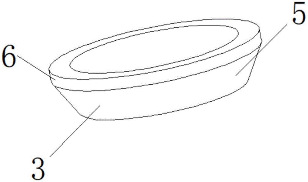
图3为本实用新型密封环的结构示意图;Fig. 3 is the structural representation of the sealing ring of the utility model;
图4为本实用新型密封环俯视图。FIG. 4 is a top view of the sealing ring of the present invention.
图中:1、阀体;2、阀球;3、密封环;4、弹簧垫;5、锥形面;6、凸起环。In the figure: 1. Valve body; 2. Valve ball; 3. Sealing ring; 4. Spring washer; 5. Conical surface; 6. Raised ring.
具体实施方式Detailed ways
下面将结合本实用新型实施例中的附图,对本实用新型实施例中的技术方案进行清楚、完整地描述,显然,所描述的实施例仅仅是本实用新型一部分实施例,而不是全部的实施例。基于本实用新型中的实施例,本领域普通技术人员在没有做出创造性劳动前提下所获得的所有其他实施例,都属于本实用新型保护的范围。The technical solutions in the embodiments of the present utility model will be clearly and completely described below with reference to the accompanying drawings in the embodiments of the present utility model. Obviously, the described embodiments are only a part of the embodiments of the present utility model, rather than all the implementations. example. Based on the embodiments of the present invention, all other embodiments obtained by those of ordinary skill in the art without creative work fall within the protection scope of the present invention.
请参阅图1-4,一种具有自动补偿性质的密封结构,包括阀体1,阀体1内部的中间位置处设置有阀球2,阀球2的一侧与阀体1的连接位置处设置有密封环3,密封环3的一侧设置有弹簧垫4,密封环3包括锥形面5和凸起环6。Please refer to Fig. 1-4, a sealing structure with automatic compensation property, including a
本实用新型通过设置锥形面5和凸起环6,使得密封环3的底部为锥形,使得密封环3与阀球2为锥面密封,加大密封性,提高了密封作用,且由于锥形面5的可调节性质,使得阀体1在该处产生泄漏点后,具备自动调节的功能,使其再次密封提高了设备的密封性。In the present invention, the
请着重参阅图1、2、3和4,密封环3和弹簧垫4皆为圆形结构,密封环3的顶部为凸起环6,密封环3的底部为锥形面5。1, 2, 3 and 4, the
该种具有自动补偿性质的密封结构通过设置密封环3、弹簧垫4与阀球2配合连接,增加了结构的密封性。The sealing structure with the self-compensating property is provided with a sealing
请着重参阅图1、3和4,锥形面5向上的倾斜角度为30°。Please refer mainly to Figures 1, 3 and 4, the angle of inclination of the
该种具有自动补偿性质的密封结构通过将锥形面5的倾斜角度设置为30°加大密封面,大大提高了密封作用。The sealing structure with self-compensating properties greatly improves the sealing effect by setting the inclination angle of the
请着重参阅图1、2、3和4,密封环3为四氟材质构成。Please refer to Figures 1, 2, 3 and 4. The
该种具有自动补偿性质的密封结构的密封环3在温度小于180oC可以采用四氟材质,温度大于180oC后必须采用柔性缠绕石墨材质。The sealing
工作原理:通过将密封环3的顶部设置为凸起环6,底部为锥形面5,在安装阀球2时,使得密封环3的结构为锥形的配合形式,使原来的平面密封改为锥面密封,加大密封面,大大提高了密封作用,且锥形结构的可调节性质,使得设备在该处产生泄漏点后,具备自动调节的功能,使其再次密封提高了设备的密封性,降低了工作难度。Working principle: By setting the top of the
对于本领域技术人员而言,显然本实用新型不限于上述示范性实施例的细节,而且在不背离本实用新型的精神或基本特征的情况下,能够以其他的具体形式实现本实用新型。因此,无论从哪一点来看,均应将实施例看作是示范性的,而且是非限制性的,本实用新型的范围由所附权利要求而不是上述说明限定,因此旨在将落在权利要求的等同要件的含义和范围内的所有变化囊括在本实用新型内。不应将权利要求中的任何附图标记视为限制所涉及的权利要求。It will be apparent to those skilled in the art that the present invention is not limited to the details of the above-described exemplary embodiments, and that the present invention can be implemented in other specific forms without departing from the spirit or essential characteristics of the present invention. Therefore, the embodiments are to be considered in all respects as exemplary and not restrictive, and the scope of the present invention is defined by the appended claims rather than the foregoing description, and it is therefore intended that the All changes within the meaning and range of the required equivalents are embraced within the present invention. Any reference signs in the claims shall not be construed as limiting the involved claim.
Claims (4)
Priority Applications (1)
| Application Number | Priority Date | Filing Date | Title |
|---|---|---|---|
| CN201922032925.5U CN210920195U (en) | 2019-11-22 | 2019-11-22 | Sealing structure with automatic compensation property |
Applications Claiming Priority (1)
| Application Number | Priority Date | Filing Date | Title |
|---|---|---|---|
| CN201922032925.5U CN210920195U (en) | 2019-11-22 | 2019-11-22 | Sealing structure with automatic compensation property |
Publications (1)
| Publication Number | Publication Date |
|---|---|
| CN210920195U true CN210920195U (en) | 2020-07-03 |
Family
ID=71363278
Family Applications (1)
| Application Number | Title | Priority Date | Filing Date |
|---|---|---|---|
| CN201922032925.5U Active CN210920195U (en) | 2019-11-22 | 2019-11-22 | Sealing structure with automatic compensation property |
Country Status (1)
| Country | Link |
|---|---|
| CN (1) | CN210920195U (en) |
Cited By (2)
| Publication number | Priority date | Publication date | Assignee | Title |
|---|---|---|---|---|
| CN111928002A (en) * | 2020-09-22 | 2020-11-13 | 四川艺诚精密机械有限公司 | Natural gas emergency cut-off valve convenient to connect |
| CN118903947A (en) * | 2024-10-09 | 2024-11-08 | 亿凯(江苏)机械科技有限公司 | High-temperature-resistant liquid leakage-proof electrolyte filter |
-
2019
- 2019-11-22 CN CN201922032925.5U patent/CN210920195U/en active Active
Cited By (2)
| Publication number | Priority date | Publication date | Assignee | Title |
|---|---|---|---|---|
| CN111928002A (en) * | 2020-09-22 | 2020-11-13 | 四川艺诚精密机械有限公司 | Natural gas emergency cut-off valve convenient to connect |
| CN118903947A (en) * | 2024-10-09 | 2024-11-08 | 亿凯(江苏)机械科技有限公司 | High-temperature-resistant liquid leakage-proof electrolyte filter |
Similar Documents
| Publication | Publication Date | Title |
|---|---|---|
| CN208687000U (en) | A kind of two way seal floating hard seal ball valve spring is against pressure and structure | |
| CN205592395U (en) | Resistant ultra -low temperature two way seal circle | |
| CN204553883U (en) | Valve | |
| CN209430757U (en) | A kind of sealing element of bulb tube connector | |
| CN206377269U (en) | Valve port sealing ring of a gas proportional valve | |
| CN209164807U (en) | Spill-proof assembly is used in a kind of connection of pipeline | |
| CN202790658U (en) | Valve seat of fixed ball valve | |
| CN108253154A (en) | The elastic sealing structure of fixed spherical ball valve valve seat | |
| CN208107206U (en) | A kind of enhanced more back seal ball valve sealing structures of segmentation structure | |
| CN213206566U (en) | A valve seat valve core sealing structure and valve | |
| CN207906468U (en) | A valve seat with cushioning function | |
| CN203670827U (en) | An inclined full sealing surface seat butterfly valve | |
| CN208487303U (en) | A kind of high leakproofness closestool adapter tube | |
| CN222543277U (en) | A new type of articulated joint | |
| CN220792134U (en) | Floating ball valve | |
| CN207701788U (en) | A kind of flexibility bidirectional sealed butterfly valve | |
| CN204300391U (en) | A kind of two way sealed high-performance butterfly valve | |
| CN217422210U (en) | Anti-leakage valve | |
| CN207584013U (en) | A kind of automobile oil-resisting type oil scraper ring | |
| CN205207755U (en) | Non -maintaining high performance ball valve | |
| CN205534267U (en) | Automatic compensation formula quck -opening valve | |
| CN210770972U (en) | Domestic safety gas valve structure | |
| CN205401752U (en) | Eccentric diaphragm butterfly valve of flange cartridge clip formula | |
| CN207621362U (en) | A kind of band angle seals auxiliary structure shut-off valve | |
| CN211501642U (en) | Medium pressurized sealing ring and its valve |
Legal Events
| Date | Code | Title | Description |
|---|---|---|---|
| GR01 | Patent grant | ||
| GR01 | Patent grant | ||
| TR01 | Transfer of patent right |
Effective date of registration: 20251124 Address after: 415500 Hunan Province, Changde City, Lixian County, Guanyuan Township, YujiaTai Village, Dongfu 5th Group Patentee after: Xie Tieping Country or region after: China Address before: 415500 floor 1-2, building 10, Chuangyuan Park, Lixian Economic Development Zone, Sanjia neighborhood committee, Lidan sub district office, Lixian County, Changde City, Hunan Province Patentee before: HUNAN GAOCI CONTROL SYSTEM TECHNOLOGY Co.,Ltd. Country or region before: China |
|
| TR01 | Transfer of patent right |