CN210916413U - High-efficient cleaning device of fly frame - Google Patents
High-efficient cleaning device of fly frame Download PDFInfo
- Publication number
- CN210916413U CN210916413U CN201921459803.8U CN201921459803U CN210916413U CN 210916413 U CN210916413 U CN 210916413U CN 201921459803 U CN201921459803 U CN 201921459803U CN 210916413 U CN210916413 U CN 210916413U
- Authority
- CN
- China
- Prior art keywords
- plate
- cleaning device
- roving frame
- fixed
- wall
- Prior art date
- Legal status (The legal status is an assumption and is not a legal conclusion. Google has not performed a legal analysis and makes no representation as to the accuracy of the status listed.)
- Expired - Fee Related
Links
Images


Landscapes
- Spinning Or Twisting Of Yarns (AREA)
Abstract
本实用新型公开了一种粗纱机的高效清洁装置,包括支撑架、升降机构和清洁机构,所述升降机构位于支撑架上,所述升降机构包括承重板和伺服电机,所述承重板固定于支撑架顶部的边侧,所述承重板底部的中心处安装有第一转轴的下端,所述第一转轴的上端依次贯穿于活动板和支撑架的内部与伺服电机的输出端相互连接,所述承重板底部的一侧固定有导向杆的下端,所述导向杆的上端贯穿于活动板的内部与支撑架的顶部相互连接;本实用新型能够将粗纱机本体产生的小颗粒悬浮物和棉絮、绒布或者碎屑吸收,且能够将吸附在过滤网底部的小颗粒悬浮物和棉絮、绒布或者碎屑扫落到收集盒的内部,同时避免了拆卸过滤网,降低了人工的劳动强度。
The utility model discloses a high-efficiency cleaning device for a roving frame, comprising a support frame, a lifting mechanism and a cleaning mechanism. The lifting mechanism is located on the support frame, and the lifting mechanism includes a load-bearing plate and a servo motor, and the load-bearing plate is fixed on On the side of the top of the support frame, the lower end of the first rotating shaft is installed at the center of the bottom of the bearing plate. One side of the bottom of the load-bearing plate is fixed with the lower end of the guide rod, and the upper end of the guide rod penetrates through the interior of the movable plate and is connected to the top of the support frame; , flannel or debris absorption, and can sweep the small suspended particles and cotton wool, flannel or debris adsorbed at the bottom of the filter screen into the inside of the collection box, while avoiding the disassembly of the filter screen and reducing the labor intensity of labor.
Description
技术领域technical field
本实用新型属于粗纱机技术领域,具体涉及一种粗纱机的高效清洁装置。The utility model belongs to the technical field of roving frames, in particular to an efficient cleaning device for a roving frame.
背景技术Background technique
在纺织厂中需要使用到粗纱机,粗纱机是把纤维条制成粗纱的纺纱机器,粗纱机主要作用是牵伸和加拈,并把粗纱卷绕成一定的卷装,以适应细纱机加工的要求。Roving frame is used in textile mills. Roving frame is a spinning machine that makes fiber strips into roving. The main function of roving frame is to draft and twist, and to wind roving into a certain package to adapt to spinning frame processing. requirements.
如公开号为CN209098888U的实用新型所公开的一种粗纱机,其虽然通过转动驱动丝杆,使滑块在滑槽内滑动,从而使安装杆从机体中导出,从而在机体外部更换原材料,更换原料方便,但是该粗纱机没有设置清洁装置,导致小颗粒悬浮物和棉絮、绒布或者碎屑四散,降低了车间的环境,为此我们提出一种粗纱机的高效清洁装置。For example, a roving frame disclosed by the utility model with the publication number of CN209098888U, although the sliding block slides in the chute by rotating the driving screw, so that the mounting rod is led out from the body, so as to replace the raw material outside the body, replace The raw material is convenient, but the roving frame is not equipped with a cleaning device, which leads to the scattering of small particle suspended matter and cotton wool, flannel or debris, which reduces the environment of the workshop. Therefore, we propose an efficient cleaning device for the roving frame.
实用新型内容Utility model content
本实用新型的目的在于提供一种粗纱机的高效清洁装置,以解决上述背景技术中提出的问题。The purpose of the present invention is to provide an efficient cleaning device for a roving frame, so as to solve the problems raised in the above background technology.
为实现上述目的,本实用新型提供如下技术方案:一种粗纱机的高效清洁装置,包括支撑架、升降机构和清洁机构,所述升降机构位于支撑架上,所述升降机构包括承重板和伺服电机,所述承重板固定于支撑架顶部的边侧,所述承重板底部的中心处安装有第一转轴的下端,所述第一转轴的上端依次贯穿于活动板和支撑架的内部与伺服电机的输出端相互连接,所述承重板底部的一侧固定有导向杆的下端,所述导向杆的上端贯穿于活动板的内部与支撑架的顶部相互连接,所述支撑架的底部固定于粗纱机本体顶部的边侧。In order to achieve the above purpose, the present utility model provides the following technical solutions: a high-efficiency cleaning device for a roving frame, comprising a support frame, a lifting mechanism and a cleaning mechanism, the lifting mechanism is located on the support frame, and the lifting mechanism includes a load-bearing plate and a servo The motor, the load-bearing plate is fixed on the side of the top of the support frame, the lower end of the first rotating shaft is installed at the center of the bottom of the load-bearing plate, and the upper end of the first rotating shaft runs through the movable plate and the inner part of the support frame and the servo motor in turn. The output ends of the motors are connected to each other, the lower end of the guide rod is fixed on one side of the bottom of the load-bearing plate, and the upper end of the guide rod penetrates through the interior of the movable plate and is connected to the top of the support frame, and the bottom of the support frame is fixed to the top of the support frame. The side of the top of the roving frame body.
优选的,所述清洁机构位于支撑架和粗纱机本体上,所述清洁机构包括中空板,所述中空板安装于活动板底部的一侧,所述中空板的底部连接有导风板,所述导风板的边侧设置有吸尘管,所述中空板的边侧连接有软管的一端,所述软管的另一端设置于分离箱的边侧,所述分离箱安装于粗纱机本体的顶部,所述分离箱边侧的顶部连接有连接管的一端,所述连接管的另一端连接有气泵,所述气泵设置于粗纱机本体的顶部。Preferably, the cleaning mechanism is located on the support frame and the roving frame body, the cleaning mechanism includes a hollow plate, the hollow plate is installed on one side of the bottom of the movable plate, and the bottom of the hollow plate is connected with an air guide plate, so The side of the air deflector is provided with a dust suction pipe, the side of the hollow plate is connected with one end of a hose, and the other end of the hose is arranged on the side of the separation box, and the separation box is installed on the roving frame The top of the main body, the top of the side of the separation box is connected with one end of a connecting pipe, the other end of the connecting pipe is connected with an air pump, and the air pump is arranged on the top of the roving frame body.
优选的,所述分离箱的内部设置有固定板,所述固定板的内部安装有过滤网,所述过滤网位于毛刷的上方,所述毛刷固定于横杆的顶部,所述横杆底部的中心处连接有第二转轴,所述第二转轴的下端贯穿于承重杆的内部,所述承重杆固定于分离箱的内壁,所述第二转轴的下端固定有第一锥形齿轮,所述第一锥形齿轮通过第二锥形齿轮与第三转轴一端相互连接,所述第三转轴的另一端依次贯穿于竖板和分离箱的内部与旋转电机相互连接,所述竖板固定于承重杆的底部。Preferably, a fixing plate is arranged inside the separation box, a filter screen is installed inside the fixing plate, the filter screen is located above the brush, the brush is fixed on the top of the cross bar, and the cross bar The center of the bottom is connected with a second rotating shaft, the lower end of the second rotating shaft penetrates the inside of the bearing rod, the bearing rod is fixed on the inner wall of the separation box, and the lower end of the second rotating shaft is fixed with a first bevel gear, The first bevel gear is connected to one end of the third rotating shaft through the second bevel gear, and the other end of the third rotating shaft is connected to the rotating motor through the interior of the vertical plate and the separation box in turn, and the vertical plate is fixed. at the bottom of the bearing bar.
优选的,所述分离箱的底部安装有收集盒,所述收集盒的外壁设置有密封件,所述分离箱的外壁固定有把手,所述把手位于分离箱的外部。Preferably, a collection box is installed on the bottom of the separation box, an outer wall of the collection box is provided with a sealing member, and a handle is fixed on the outer wall of the separation box, and the handle is located outside the separation box.
优选的,所述第一转轴的外壁和活动板的内壁均设计为螺纹状结构,且活动板与第一转轴为螺纹连接。Preferably, both the outer wall of the first rotating shaft and the inner wall of the movable plate are designed as threaded structures, and the movable plate and the first rotating shaft are connected by threads.
优选的,所述导向杆关于活动板的中心轴线对称设置有两个,且活动板与导向杆构成滑动连接。Preferably, two guide rods are symmetrically arranged with respect to the central axis of the movable plate, and the movable plate and the guide rod form a sliding connection.
优选的,所述吸尘管在导风板的边侧等间距分布,且导风板在中空板的底部等间距分布,并且导风板与吸尘管和中空板均为贯通连接。Preferably, the dust suction pipes are distributed at equal intervals on the sides of the air guide plate, and the air guide plates are distributed at equal intervals at the bottom of the hollow plate, and the air guide plates are connected with the dust suction pipe and the hollow plate through.
优选的,所述过滤网设计为圆形结构,且过滤网的直径小于横杆的长度3cm,并且横杆与过滤网相互平行设计。Preferably, the filter screen is designed in a circular structure, and the diameter of the filter screen is smaller than the length of the crossbar by 3 cm, and the crossbar and the filter screen are designed to be parallel to each other.
优选的,所述第一锥形齿轮和第二锥形齿轮相互垂直设计,且第一锥形齿轮和第二锥形齿轮为啮合连接。Preferably, the first bevel gear and the second bevel gear are designed to be perpendicular to each other, and the first bevel gear and the second bevel gear are in meshing connection.
优选的,所述密封件的内壁与收集盒的外壁为粘贴连接,且密封件的外壁与分离箱的内壁相互贴合。Preferably, the inner wall of the sealing member and the outer wall of the collection box are connected by adhesive bonding, and the outer wall of the sealing member and the inner wall of the separation box are attached to each other.
与现有技术相比,本实用新型的有益效果是:Compared with the prior art, the beneficial effects of the present utility model are:
1、设置有升降机构,在升降机构的带动下,使得吸尘管能够升降,从而能够移动到粗纱机本体的前端,进而能够将粗纱机本体产生的小颗粒悬浮物和棉絮、绒布或者碎屑吸收,同时吸尘管能够收纳,不会影响粗纱机本体的正常使用,保证了工人能够在良好的环境工作。1. A lifting mechanism is provided. Driven by the lifting mechanism, the dust suction pipe can be lifted and lowered, so that it can move to the front end of the roving frame, and then can remove the small suspended particles and cotton wool, flannel or debris generated by the roving frame. At the same time, the vacuum tube can be stored, which will not affect the normal use of the roving frame, ensuring that workers can work in a good environment.
2、设置有横杆和毛刷,且横杆和毛刷能够进行旋转,从而能够将吸附在过滤网底部的小颗粒悬浮物和棉絮、绒布或者碎屑扫落到收集盒的内部,从而便于集中处理,同时避免了拆卸过滤网,降低了人工的劳动强度。2. There are crossbars and brushes, and the crossbars and brushes can be rotated, so that the small suspended particles and cotton wool, flannel or debris adsorbed on the bottom of the filter can be swept into the inside of the collection box, so as to facilitate Centralized processing, while avoiding the disassembly of the filter screen, reducing the labor intensity of labor.
附图说明Description of drawings
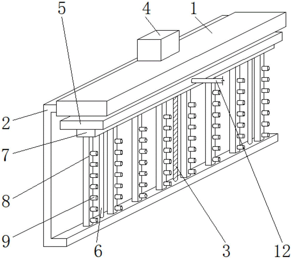
图1为本实用新型局部立体结构示意图;Fig. 1 is the partial three-dimensional structure schematic diagram of the present utility model;
图2为本实用新型整体正视结构示意图;Fig. 2 is the overall front view structure schematic diagram of the utility model;
图3为本实用新型图2中A处放大结构示意图;Fig. 3 is the enlarged schematic diagram of the structure at place A in Fig. 2 of the utility model;
图4为本实用新型图3中过滤网安装结构示意图;4 is a schematic diagram of the installation structure of the filter screen in FIG. 3 of the present utility model;
图5为本实用新型图3中收集盒安装结构示意图;5 is a schematic diagram of the installation structure of the collection box in FIG. 3 of the present utility model;
图6为本实用新型图1中导向杆安装结构示意图;6 is a schematic diagram of the installation structure of the guide rod in FIG. 1 of the present utility model;
图中:1、支撑架;2、承重板;3、第一转轴;4、伺服电机;5、活动板;6、导向杆;7、中空板;8、导风板;9、吸尘管;10、粗纱机本体;11、分离箱;12、软管;13、收集盒;14、密封件;15、把手;16、固定板;17、过滤网;18、毛刷;19、横杆;20、第二转轴;21、承重杆;22、第一锥形齿轮;23、第二锥形齿轮;24、第三转轴;25、竖板;26、旋转电机;27、连接管;28、气泵。In the figure: 1. Supporting frame; 2. Load-bearing plate; 3. First rotating shaft; 4. Servo motor; 5. Active plate; 6. Guide rod; 7. Hollow plate; 8. Air deflector; ; 10, roving frame body; 11, separation box; 12, hose; 13, collection box; 14, seal; 15, handle; 16, fixing plate; 17, filter screen; 18, brush; ; 20, the second shaft; 21, the load-bearing rod; 22, the first bevel gear; 23, the second bevel gear; 24, the third shaft; 25, the vertical plate; 26, the rotating motor; 27, the connecting pipe; 28 ,air pump.
具体实施方式Detailed ways
下面将结合本实用新型实施例中的附图,对本实用新型实施例中的技术方案进行清楚、完整地描述,显然,所描述的实施例仅仅是本实用新型一部分实施例,而不是全部的实施例。基于本实用新型中的实施例,本领域普通技术人员在没有做出创造性劳动前提下所获得的所有其他实施例,都属于本实用新型保护的范围。The technical solutions in the embodiments of the present utility model will be clearly and completely described below with reference to the accompanying drawings in the embodiments of the present utility model. Obviously, the described embodiments are only a part of the embodiments of the present utility model, rather than all the implementations. example. Based on the embodiments of the present invention, all other embodiments obtained by those of ordinary skill in the art without creative work fall within the protection scope of the present invention.
请参阅图1-6,本实用新型提供技术方案:一种粗纱机的高效清洁装置,包括支撑架1、升降机构和清洁机构,升降机构位于支撑架1上,升降机构包括承重板2和伺服电机4,承重板2固定于支撑架1顶部的边侧,承重板2底部的中心处安装有第一转轴3的下端,第一转轴3的上端依次贯穿于活动板5和支撑架1的内部与伺服电机4的输出端相互连接,承重板2底部的一侧固定有导向杆6的下端,导向杆6的上端贯穿于活动板5的内部与支撑架1的顶部相互连接,支撑架1的底部固定于粗纱机本体10顶部的边侧,在升降机构的带动下,使得吸尘管9能够升降,从而能够移动到粗纱机本体10的前端,进而能够将粗纱机本体10产生的小颗粒悬浮物和棉絮、绒布或者碎屑吸收,同时吸尘管9能够收纳,不会影响粗纱机本体10的正常使用,保证了工人能够在良好的环境工作。Please refer to FIGS. 1-6, the present utility model provides a technical solution: a high-efficiency cleaning device for a roving frame, comprising a
能够对粗纱机本体10产生的小颗粒悬浮物和棉絮、绒布或者碎屑吸收,本实施案例,优选的,清洁机构位于支撑架1和粗纱机本体10上,清洁机构包括中空板7,中空板7安装于活动板5底部的一侧,中空板7的底部连接有导风板8,导风板8的边侧设置有吸尘管9,中空板7的边侧连接有软管12的一端,软管12的另一端设置于分离箱11的边侧,分离箱11安装于粗纱机本体10的顶部,分离箱11边侧的顶部连接有连接管27的一端,连接管27的另一端连接有气泵28,气泵28设置于粗纱机本体10的顶部。It can absorb small suspended particles and cotton wool, flannel or debris generated by the roving
能够将吸附在过滤网17底部的小颗粒悬浮物和棉絮、绒布或者碎屑扫落到收集盒13的内部,从而便于集中处理,同时避免了拆卸过滤网17,降低了人工的劳动强度,本实施案例,优选的,分离箱11的内部设置有固定板16,固定板16的内部安装有过滤网17,过滤网17位于毛刷18的上方,毛刷18固定于横杆19的顶部,横杆19底部的中心处连接有第二转轴20,第二转轴20的下端贯穿于承重杆21的内部,承重杆21固定于分离箱11的内壁,第二转轴20的下端固定有第一锥形齿轮22,第一锥形齿轮22通过第二锥形齿轮23与第三转轴24一端相互连接,第三转轴24的另一端依次贯穿于竖板25和分离箱11的内部与旋转电机26相互连接,竖板25固定于承重杆21的底部。The small suspended solids and cotton wool, flannel or debris adsorbed at the bottom of the
保证了分离箱11与收集盒13之间连接的密闭性,同时通过把手15能够将收集盒13从分离箱11的内部拉出,本实施案例,优选的,分离箱11的底部安装有收集盒13,收集盒13的外壁设置有密封件14,分离箱11的外壁固定有把手15,把手15位于分离箱11的外部。The airtightness of the connection between the
保证了第一转轴3正转或者反转时,活动板5在导向杆6的限位下能够进行升降,本实施案例,优选的,第一转轴3的外壁和活动板5的内壁均设计为螺纹状结构,且活动板5与第一转轴3为螺纹连接,导向杆6关于活动板5的中心轴线对称设置有两个,且活动板5与导向杆6构成滑动连接。It is ensured that when the first
增加了吸尘的有效面积,从而提升了吸尘的效率,本实施案例,优选的,吸尘管9在导风板8的边侧等间距分布,且导风板8在中空板7的底部等间距分布,并且导风板8与吸尘管9和中空板7均为贯通连接。The effective area for dust collection is increased, thereby improving the efficiency of dust collection. In this implementation case, preferably, the
保证了横杆19旋转时,横杆19上的毛刷18能够扫到过滤网17的底部,从而能够将过滤网17底部的小颗粒悬浮物等扫落到收集盒13的内部,本实施案例,优选的,过滤网17设计为圆形结构,且过滤网17的直径小于横杆19的长度3cm,并且横杆19与过滤网17相互平行设计。It is ensured that when the
保证了水平方向的旋转能够转化成竖直方向的旋转,从而方便旋转电机26的安装,本实施案例,优选的,第一锥形齿轮22和第二锥形齿轮23相互垂直设计,且第一锥形齿轮22和第二锥形齿轮23为啮合连接。It is ensured that the rotation in the horizontal direction can be converted into the rotation in the vertical direction, thereby facilitating the installation of the
保证了分离箱11与收集盒13之间连接的密闭性,使得清洁机构能够正转运行,本实施案例,优选的,密封件14的内壁与收集盒13的外壁为粘贴连接,且密封件14的外壁与分离箱11的内壁相互贴合。The airtightness of the connection between the
本实用新型的工作原理及使用流程:该装置在使用时,首先启动伺服电机4进行正转,接着伺服电机4带动第一转轴3正转,由于第一转轴3与活动板5为螺纹连接,因此活动板5在导向杆6的限位向下移动,从而使得吸尘管9移动到粗纱机本体10的前端,然后启动气泵28,气泵28产生吸力,依次通过连接管27、分离箱11、软管12、活动板5、中空板7和导风板8传递至吸尘管9处,由于吸尘管9和导风板8均设置有多个,因此增加了吸尘的有效面积,然后粗纱机本体10产生的小颗粒悬浮物和棉絮、绒布或者碎屑进入到分离箱11的内部,粗纱机本体10产生的小颗粒悬浮物和棉絮、绒布或者碎屑被过滤网17拦截,空气被排出,当过滤网17需要清理时,此时启动旋转电机26,接着旋转电机26通过第三转轴24、第二锥形齿轮23、第一锥形齿轮22和第二转轴20带动横杆19和毛刷18旋转,从而能够将吸附在过滤网17底部的小颗粒悬浮物和棉絮、绒布或者碎屑扫落到收集盒13的内部,然后通过把手15,即可将收集盒13从分离箱11的内部拉出,然后将收集盒13内部垃圾清理完毕后安装回原处即可。The working principle and use process of the utility model: when the device is in use, the
尽管已经示出和描述了本实用新型的实施例,对于本领域的普通技术人员而言,可以理解在不脱离本实用新型的原理和精神的情况下可以对这些实施例进行多种变化、修改、替换和变型,本实用新型的范围由所附权利要求及其等同物限定。Although the embodiments of the present invention have been shown and described, it will be understood by those skilled in the art that various changes and modifications can be made to these embodiments without departing from the principles and spirit of the present invention , alternatives and modifications, the scope of the present invention is defined by the appended claims and their equivalents.
Claims (10)
Priority Applications (1)
| Application Number | Priority Date | Filing Date | Title |
|---|---|---|---|
| CN201921459803.8U CN210916413U (en) | 2019-09-04 | 2019-09-04 | High-efficient cleaning device of fly frame |
Applications Claiming Priority (1)
| Application Number | Priority Date | Filing Date | Title |
|---|---|---|---|
| CN201921459803.8U CN210916413U (en) | 2019-09-04 | 2019-09-04 | High-efficient cleaning device of fly frame |
Publications (1)
| Publication Number | Publication Date |
|---|---|
| CN210916413U true CN210916413U (en) | 2020-07-03 |
Family
ID=71367733
Family Applications (1)
| Application Number | Title | Priority Date | Filing Date |
|---|---|---|---|
| CN201921459803.8U Expired - Fee Related CN210916413U (en) | 2019-09-04 | 2019-09-04 | High-efficient cleaning device of fly frame |
Country Status (1)
| Country | Link |
|---|---|
| CN (1) | CN210916413U (en) |
-
2019
- 2019-09-04 CN CN201921459803.8U patent/CN210916413U/en not_active Expired - Fee Related
Similar Documents
| Publication | Publication Date | Title |
|---|---|---|
| CN108939790B (en) | Weaving machine weaving dirt collection device | |
| CN217888299U (en) | A high-efficient electrostatic precipitator for power plant | |
| CN216229965U (en) | A chip collection device for man-made fiber board cutting | |
| CN214019744U (en) | Bag-type dust collector with self-cleaning function | |
| CN209178553U (en) | A kind of dust removal device for spinning frame | |
| CN216498117U (en) | A dust collector for cotton yarn production and processing | |
| CN211660691U (en) | Waste treatment device for spinning | |
| CN220888081U (en) | Device for removing textile dust from cloth | |
| CN207628779U (en) | A kind of curtain automatic cleaning apparatus | |
| CN219260394U (en) | A large double-sided knitting machine capable of automatic dust removal | |
| CN211311715U (en) | A roving frame for cashmere yarn processing | |
| CN213086169U (en) | Air-flowing type scutcher convenient for seed cotton separation | |
| CN216989112U (en) | Dust collecting and processing equipment of blowing machine for yarn production | |
| CN219861757U (en) | Fine hair clearing device for roving frame | |
| CN219647005U (en) | High-efficiency gas dust remover | |
| CN217770009U (en) | Photovoltaic board cleaning device | |
| CN211585738U (en) | Middle-effect filter with cleaning device | |
| CN220034797U (en) | Spinning line dust collector | |
| CN218608524U (en) | Dust collector is used in knitted fabric production | |
| CN222455371U (en) | A spinning dust collecting and processing device for a spinning machine | |
| CN112575421A (en) | A clear fine hair device for fly frame | |
| CN221760076U (en) | Dust collector for weaving machine | |
| CN219174840U (en) | Non-woven fabric cleaning device | |
| CN111748883A (en) | Dust collecting equipment for spinning | |
| CN216838677U (en) | Quick dust collector in printing and dyeing cloth surface |
Legal Events
| Date | Code | Title | Description |
|---|---|---|---|
| GR01 | Patent grant | ||
| GR01 | Patent grant | ||
| CF01 | Termination of patent right due to non-payment of annual fee |
Granted publication date: 20200703 |