CN210907694U - Automatic metalwork stamping die of liftout - Google Patents
Automatic metalwork stamping die of liftout Download PDFInfo
- Publication number
- CN210907694U CN210907694U CN201921677902.3U CN201921677902U CN210907694U CN 210907694 U CN210907694 U CN 210907694U CN 201921677902 U CN201921677902 U CN 201921677902U CN 210907694 U CN210907694 U CN 210907694U
- Authority
- CN
- China
- Prior art keywords
- plate
- fixedly connected
- rotating
- stamping die
- block
- Prior art date
- Legal status (The legal status is an assumption and is not a legal conclusion. Google has not performed a legal analysis and makes no representation as to the accuracy of the status listed.)
- Expired - Fee Related
Links
Images


Landscapes
- Shaping Metal By Deep-Drawing, Or The Like (AREA)
Abstract
The utility model provides an automatic metalwork stamping die of liftout relates to the stamping die field. This automatic metalwork stamping die of liftout, the power distribution box comprises a box body, the spout has all been seted up to the both sides face of box, and the equal sliding connection in inside of two spouts has two symmetrical sliders, and the inside of box is equipped with the connecting block, the first rotation piece of top surface fixedly connected with of connecting block, and the inside rotation of first rotation piece is connected with first rotation board. This metalwork stamping die of automatic liftout, through setting up ejection groove, the ejector pin, the linkage plate, first rotor plate, the connecting block, the slider, the spout, the second rotor plate, the third rotor plate, backup pad and fixed plate, possess workman low in labor strength, factor of safety is high, the cost of manufacture is low and the advantage of liftout speed piece, solved current stamping die manual work and got the material, the problem that intensity of labour is high and have the potential safety hazard uses the motor with liftout mechanism liftout, the cost of manufacture is high and the slow problem of liftout speed.
Description
Technical Field
The utility model relates to a stamping die technical field specifically is an automatic metalwork stamping die of liftout.
Background
A stamping die is a special processing equipment for processing a material (metal or nonmetal) into a part (or a semi-finished product) in cold stamping, and is called a cold stamping die (commonly called a cold stamping die), and stamping is a pressure processing method for applying pressure to the material by using a die installed on a press machine at room temperature to separate or plastically deform the material so as to obtain a required part.
The product after stamping of the stamping die needs to be manually taken out by a worker or ejected by an ejection mechanism, the demolding efficiency of the manually taken product is low, the labor intensity of the worker is increased, potential safety hazards exist, the ejection mechanism needs to use a motor, the manufacturing cost is high, and the ejection speed is low.
SUMMERY OF THE UTILITY MODEL
The utility model aims at providing an automatic metalwork stamping die of liftout solves the problem that proposes in the background art.
Technical scheme
In order to achieve the above purpose, the utility model discloses a following technical scheme realizes: a metal piece stamping die capable of automatically ejecting materials comprises a box body, wherein two side faces of the box body are respectively provided with a sliding groove, two symmetrical sliding blocks are respectively and slidably connected inside the two sliding grooves, a connecting block is arranged inside the box body, the top face of the connecting block is fixedly connected with a first rotating block, a first rotating plate is rotatably connected inside the first rotating block, one end, far away from the first rotating block, of the first rotating plate is rotatably connected with a second rotating block, a linkage plate is arranged above the second rotating block, the top face of the linkage plate is fixedly connected with an ejector rod, one side face, far away from the connecting block, of each sliding block is fixedly connected with a third rotating block, a second rotating plate is rotatably connected inside each third rotating block, a lower die is fixedly connected to the center of the top face of the box body, an ejecting groove is formed inside the lower die, two ends of the top face of the box body are, and the bottom surface of roof and the top surface fixed connection of guide bar, the center fixedly connected with pneumatic cylinder of roof top surface, the output fixedly connected with fixed plate of pneumatic cylinder, the bottom surface fixedly connected with of fixed plate goes up the mould, the equal fixedly connected with two symmetrical fourth turning blocks of both sides face of fixed plate, the inside of every fourth turning block all rotates and is connected with the third rotor plate, the one end that the fourth turning block was kept away from to every third rotor plate all rotates and is connected with the backup pad.
Further, the top surface fixedly connected with spring of linkage plate, the top surface of spring and the interior roof fixed connection of box, the ejector pin is located the inside of spring, through setting up the spring, supports the linkage plate, promotes the reset speed of linkage plate to promote the liftout speed of ejector pin.
Furthermore, two symmetrical through holes are formed in the top of the fixing plate, the fixing plate is connected with the guide rod in a sliding mode through the through holes, and the fixing plate slides on the guide rod through the through holes, so that the accuracy of closing the upper die and the lower die is improved, and the dislocation of the closed die is avoided.
Furthermore, the ejector rod is matched with the ejection groove, and the horizontal plane of the top surface of the ejector rod is higher than the horizontal plane of the top surface of the ejection groove, so that the situation that the ejection length of the ejector rod in the ejection groove is insufficient, and the ejection of a workpiece fails is avoided.
Furthermore, the bottom surface of linkage board and the top surface fixed connection of second turning block, the both sides face of connecting block respectively with the side fixed connection that two sliders are close to each other, through setting up spout and slider, make the slider slide in the inside of spout to stability when promoting the slider and removing.
Furthermore, one side face, far away from the third rotating plate, of the supporting plate is rotatably connected with one end, far away from the third rotating block, of the second rotating plate, the opening direction of the third rotating block is the same as that of the fourth rotating block, and the supporting plate is arranged, so that the third rotating plate rotates for a certain angle on the supporting plate and then pushes the supporting plate to descend, and therefore the rotating angle of the second rotating plate is reduced, and the moving range of the fixing plate is enlarged.
Furthermore, the opening direction of the first rotating block is opposite to that of the second rotating block, the maximum cross-sectional length of the first rotating plate is the same as the maximum moving distance of the sliding block in the sliding groove, and therefore the stability is higher when the first rotating plate rotates to 90 degrees in the first rotating block and the second rotating block.
1. The automatic ejection metal piece stamping die is characterized in that an ejection groove, an ejector rod, a linkage plate, a first rotating plate, a connecting block, sliding blocks, a sliding groove, a second rotating plate, a third rotating plate, a supporting plate and a fixed plate are arranged, when a stamping die is assembled, the fixed plate descends to drive the third rotating plate to rotate on the supporting plate, rotate the second rotating plate on the supporting plate and descend, so that the two sliding blocks are far away from each other in the sliding groove, the first rotating plate rotates in the first rotating block and the second rotating block, the linkage plate drives the ejector rod to descend, when the die is assembled, the fixed plate drives the third rotating plate to ascend, so that the supporting plate drives the second rotating plate to ascend, the second rotating plate rotates in the third rotating block, the two sliding blocks are close to each other, and the first rotating plate rotates in the first rotating block and the second rotating block to a vertical state, thereby make the ejector pin stretch out from ejecting inslot, reached the effect to the automatic liftout of work piece, possess workman low in labor strength, factor of safety height, cost of manufacture low and the advantage of liftout speed piece, solved current stamping die manual work and got the material, high and the problem that has the potential safety hazard of intensity of labour and liftout mechanism liftout use the motor, cost of manufacture is high and the slow problem of liftout speed.
2. This automatic metalwork stamping die of liftout supports the linkage plate through setting up the spring, promotes the speed that resets of linkage plate to promote the liftout speed of ejector pin, through setting up the through-hole, make the fixed plate slide on the guide bar, thereby promote the accuracy when mould and bed die compound die, avoid the compound die dislocation, through setting up spout and slider, make the slider slide in the inside of spout, thereby promote the stability when slider removes.
Drawings
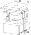
Fig. 1 is a perspective view of the top plate of the present invention;
FIG. 2 is a sectional view of the box body of the present invention;
fig. 3 is a cross-sectional view of a perspective view of the box body of the present invention.
The device comprises a box body 1, a sliding groove 2, a sliding block 3, a connecting block 4, a first rotating block 5, a first rotating plate 6, a second rotating block 7, a linkage plate 8, a push rod 9, a spring 10, a third rotating block 11, a second rotating plate 12, a lower die 13, a push groove 14, a guide rod 15, a top plate 16, a hydraulic cylinder 17, a fixed plate 18, a through hole 19, a fourth rotating block 20, a third rotating plate 21, a support plate 22 and an upper die 23.
Detailed Description
As shown in fig. 1-3, an embodiment of the present invention provides an automatic material ejection metal part stamping die, which includes a box body 1, wherein two side surfaces of the box body 1 are respectively provided with a sliding groove 2, two symmetrical sliding blocks 3 are respectively slidably connected inside the two sliding grooves 2, a connecting block 4 is arranged inside the box body 1, a first rotating block 5 is fixedly connected to a top surface of the connecting block 4, a first rotating plate 6 is rotatably connected inside the first rotating block 5, one end of the first rotating plate 6, which is far away from the first rotating block 5, is rotatably connected to a second rotating block 7, an opening direction of the first rotating block 5 is opposite to an opening direction of the second rotating block 7, a maximum transverse length of the first rotating plate 6 is the same as a maximum moving distance of the sliding blocks 3 in the sliding grooves 2, so that the stability of the first rotating plate 6 is higher when the first rotating block 5 and the second rotating block 7 rotate to 90 degrees, a linkage plate 8 is arranged above the second rotating block, top surface fixedly connected with ejector pin 9 of linkage plate 8, the top surface fixedly connected with spring 10 of linkage plate 8, the top surface of spring 10 and the interior roof fixed connection of box 1, ejector pin 9 is located the inside of spring 10, through setting up spring 10, support linkage plate 8, promote linkage plate 8's speed of resetting, thereby promote ejector pin 9's liftout speed, every slider 3 keeps away from the equal fixedly connected with third turning block 11 in a side of connecting block 4, linkage plate 8's bottom surface and second turning block 7's top surface fixed connection, the both sides face of connecting block 4 respectively with the side fixed connection that two sliders 3 are close to each other, through setting up spout 2 and slider 3, make slider 3 slide in the inside of spout 2, thereby promote the stability when slider 3 removes.
A second rotating plate 12 is rotatably connected inside each third rotating block 11, a lower die 13 is fixedly connected to the center of the top surface of the box body 1, an ejection groove 14 is formed inside the lower die 13, the ejector rod 9 is matched with the ejection groove 14, the horizontal plane of the top surface of the ejector rod 9 is higher than the horizontal plane of the top surface of the ejection groove 14, so that the situation that the ejection length of the ejector rod 9 in the ejection groove 14 is insufficient and the ejection failure of a workpiece is caused is avoided, guide rods 15 are fixedly connected to both ends of the top surface of the box body 1, a top plate 16 is arranged above the guide rods 15, the bottom surface of the top plate 16 is fixedly connected with the top surface of the guide rods 15, a hydraulic cylinder 17 is fixedly connected to the center of the top surface of the top plate 16, a fixing plate 18 is fixedly connected to the output end of the hydraulic cylinder 17, an upper die 23 is fixedly connected to the bottom surface of the fixing plate 18, through the arrangement of the through hole 19, the fixed plate 18 slides on the guide rod 15, so that the accuracy of die assembly of the upper die 23 and the lower die 13 is improved, die assembly dislocation is avoided, two symmetrical fourth rotating blocks 20 are fixedly connected to both side surfaces of the fixed plate 18, a third rotating plate 21 is rotatably connected to the inside of each fourth rotating block 20, a supporting plate 22 is rotatably connected to one end of each third rotating plate 21, which is far away from the fourth rotating block 20, one side surface of the supporting plate 22, which is far away from the third rotating plate 21, is rotatably connected to one end of the second rotating plate 12, which is far away from the third rotating block 11, the opening direction of the third rotating block 11 is the same as the opening direction of the fourth rotating block 20, by arranging the supporting plate 22, the third rotating plate 21 rotates a certain angle on the supporting plate 22 and then pushes the supporting plate 22 to descend, thereby increasing the moving range of the fixed plate 18 for lowering the rotation angle of the second rotating plate 12.
When the punching die is used, an un-punched workpiece is placed at the top of the lower die 13, the hydraulic cylinder 17 is started to enable the output end of the hydraulic cylinder to descend, so that the fixed plate 18 slides and descends on the guide rod 15 through the through hole 19, the third rotating plate 21 rotates in the fourth rotating block 20, the third rotating plate 21 pushes the supporting plate 22 to descend, the second rotating plate 12 rotates in the third rotating block 11, the third rotating block 11 drives the sliding block 3 to slide in the sliding groove 2 in the direction away from the linkage plate 8, the first rotating plate 6 rotates in the first rotating block 5 and the second rotating block 7, the linkage plate 8 descends, the ejector rod 9 descends in the ejection groove 14, the spring 10 is stretched, the upper die 23 and the lower die 13 are matched, so that the workpiece is punched, the hydraulic cylinder 17 is started to enable the output end of the hydraulic cylinder to ascend, so that the fixed plate 18 ascends on the guide rod 15 through the through hole 19, therefore, the third rotating plate 21 rotates reversely in the fourth rotating block 20, the supporting plate 22 is pulled to rise, the second rotating plate 12 rotates reversely in the third rotating block 11, the sliding block 3 moves towards the direction close to the linkage plate 8, the first rotating plate 6 rotates in the first rotating block 5 and the second rotating block 7 to be in a vertical state, the ejector rod 9 extends out of the ejection groove 14, and a workpiece formed in the lower die 13 is ejected.
Claims (7)
1. The utility model provides an automatic metalwork stamping die of liftout, includes box (1), its characterized in that: the two side faces of the box body (1) are respectively provided with a sliding groove (2), two symmetrical sliding blocks (3) are respectively and slidably connected into the two sliding grooves (2), a connecting block (4) is arranged inside the box body (1), a first rotating block (5) is fixedly connected onto the top face of the connecting block (4), a first rotating plate (6) is rotatably connected into the first rotating block (5), a second rotating block (7) is rotatably connected onto one end, far away from the first rotating block (5), of the first rotating plate (6), a linkage plate (8) is arranged above the second rotating block (7), a top face of the linkage plate (8) is fixedly connected with a push rod (9), a third rotating block (11) is fixedly connected onto one side face, far away from the connecting block (4), of each sliding block (3), a second rotating plate (12) is rotatably connected into the inside of each third rotating block (11), and a lower die (13) is fixedly connected onto the center of the top face of, ejecting groove (14) have been seted up to the inside of bed die (13), equal fixedly connected with guide bar (15) in both ends of box (1) top surface, the top of guide bar (15) is equipped with roof (16), and the bottom surface of roof (16) and the top surface fixed connection of guide bar (15), the center fixedly connected with pneumatic cylinder (17) of roof (16) top surface, the output fixedly connected with fixed plate (18) of pneumatic cylinder (17), mould (23) are gone up to the bottom surface fixedly connected with of fixed plate (18), two symmetrical fourth turning blocks (20) of the equal fixedly connected with in both sides face of fixed plate (18), the inside of every fourth turning block (20) all rotates and is connected with third rotor plate (21), the one end that fourth turning block (20) were kept away from in every third rotor plate (21) all rotates and is connected with backup pad (22).
2. The automatic ejection metal piece stamping die as claimed in claim 1, wherein: the top surface of the linkage plate (8) is fixedly connected with a spring (10), the top surface of the spring (10) is fixedly connected with the inner top wall of the box body (1), and the ejector rod (9) is located inside the spring (10).
3. The automatic ejection metal piece stamping die as claimed in claim 1, wherein: two symmetrical through holes (19) are formed in the top of the fixing plate (18), and the fixing plate (18) is connected with the guide rod (15) in a sliding mode through the through holes (19).
4. The automatic ejection metal piece stamping die as claimed in claim 1, wherein: the ejector rod (9) is matched with the ejection groove (14), and the horizontal plane where the top surface of the ejector rod (9) is located is higher than the horizontal plane where the top surface of the ejection groove (14) is located.
5. The automatic ejection metal piece stamping die as claimed in claim 1, wherein: the bottom surface of the linkage plate (8) is fixedly connected with the top surface of the second rotating block (7), and two side surfaces of the connecting block (4) are fixedly connected with the side surfaces, close to the two sliding blocks (3), respectively.
6. The automatic ejection metal piece stamping die as claimed in claim 1, wherein: one side face, far away from the third rotating plate (21), of the supporting plate (22) is rotatably connected with one end, far away from the third rotating block (11), of the second rotating plate (12), and the opening direction of the third rotating block (11) is the same as that of the fourth rotating block (20).
7. The automatic ejection metal piece stamping die as claimed in claim 1, wherein: the opening direction of the first rotating block (5) is opposite to that of the second rotating block (7), and the maximum transverse length of the first rotating plate (6) is the same as the maximum moving distance of the sliding block (3) in the sliding groove (2).
Priority Applications (1)
| Application Number | Priority Date | Filing Date | Title |
|---|---|---|---|
| CN201921677902.3U CN210907694U (en) | 2019-10-09 | 2019-10-09 | Automatic metalwork stamping die of liftout |
Applications Claiming Priority (1)
| Application Number | Priority Date | Filing Date | Title |
|---|---|---|---|
| CN201921677902.3U CN210907694U (en) | 2019-10-09 | 2019-10-09 | Automatic metalwork stamping die of liftout |
Publications (1)
| Publication Number | Publication Date |
|---|---|
| CN210907694U true CN210907694U (en) | 2020-07-03 |
Family
ID=71356634
Family Applications (1)
| Application Number | Title | Priority Date | Filing Date |
|---|---|---|---|
| CN201921677902.3U Expired - Fee Related CN210907694U (en) | 2019-10-09 | 2019-10-09 | Automatic metalwork stamping die of liftout |
Country Status (1)
| Country | Link |
|---|---|
| CN (1) | CN210907694U (en) |
Cited By (2)
| Publication number | Priority date | Publication date | Assignee | Title |
|---|---|---|---|---|
| CN112496189A (en) * | 2020-11-12 | 2021-03-16 | 长春一汽四环力达冲压制品有限公司 | Automatic bending device for vehicle thermal forming floor beam |
| CN112893502A (en) * | 2021-01-22 | 2021-06-04 | 陈文杰 | Effectual aluminium alloy extrusion die of shock attenuation |
-
2019
- 2019-10-09 CN CN201921677902.3U patent/CN210907694U/en not_active Expired - Fee Related
Cited By (2)
| Publication number | Priority date | Publication date | Assignee | Title |
|---|---|---|---|---|
| CN112496189A (en) * | 2020-11-12 | 2021-03-16 | 长春一汽四环力达冲压制品有限公司 | Automatic bending device for vehicle thermal forming floor beam |
| CN112893502A (en) * | 2021-01-22 | 2021-06-04 | 陈文杰 | Effectual aluminium alloy extrusion die of shock attenuation |
Similar Documents
| Publication | Publication Date | Title |
|---|---|---|
| CN211052249U (en) | Metal plate stamping device capable of being replaced quickly | |
| CN212664687U (en) | Stamping die based on demoulding component | |
| CN211071475U (en) | Digit control machine tool mould punching press mechanism | |
| CN117259529A (en) | Cold stamping forming device and forming method for high-strength aluminum alloy plate | |
| CN107008801A (en) | A kind of continuous punching hole forming process equipment | |
| CN113798393A (en) | Punching die | |
| CN217166119U (en) | Auxiliary structure of stamping die | |
| CN223670066U (en) | Multi-station punching machine | |
| CN219746127U (en) | Stamping forming device of bridge pier arc-shaped template | |
| CN220591310U (en) | Stamping die plane detection device | |
| CN209156750U (en) | A kind of lead pipe extrusion forming device | |
| CN219193659U (en) | Automatic runner device of cutting of laser | |
| CN213613908U (en) | Claw utmost point forges mould | |
| CN108422699B (en) | Accurate positioning device for upper die and lower die | |
| CN217315582U (en) | Safe workpiece taking device for stamping workpiece | |
| CN212760793U (en) | Stamping die ejection mechanism | |
| CN213104118U (en) | Stamping die is used in metal work piece processing | |
| CN211330992U (en) | Hardware stamping die | |
| CN113198936B (en) | Stamping device is used in aluminium alloy ex-trusions processing | |
| CN222805942U (en) | Synchronous stamping die of many parts | |
| CN220196064U (en) | Continuous forming die for metal part machining | |
| CN117505570B (en) | Cold extrusion device for processing shock absorber piston | |
| CN221312174U (en) | Stamping type metal die | |
| CN212494897U (en) | Stamping die convenient for demolding | |
| CN221231427U (en) | Zirconium cup stamping forming die |
Legal Events
| Date | Code | Title | Description |
|---|---|---|---|
| GR01 | Patent grant | ||
| GR01 | Patent grant | ||
| CF01 | Termination of patent right due to non-payment of annual fee |
Granted publication date: 20200703 Termination date: 20211009 |
|
| CF01 | Termination of patent right due to non-payment of annual fee |