CN210896852U - Power transformer shell with good heat dissipation performance - Google Patents
Power transformer shell with good heat dissipation performance Download PDFInfo
- Publication number
- CN210896852U CN210896852U CN201921397238.7U CN201921397238U CN210896852U CN 210896852 U CN210896852 U CN 210896852U CN 201921397238 U CN201921397238 U CN 201921397238U CN 210896852 U CN210896852 U CN 210896852U
- Authority
- CN
- China
- Prior art keywords
- fixedly connected
- heat dissipation
- shell
- power transformer
- casing
- Prior art date
- Legal status (The legal status is an assumption and is not a legal conclusion. Google has not performed a legal analysis and makes no representation as to the accuracy of the status listed.)
- Expired - Fee Related
Links
- 230000017525 heat dissipation Effects 0.000 title claims abstract description 44
- RYGMFSIKBFXOCR-UHFFFAOYSA-N Copper Chemical compound [Cu] RYGMFSIKBFXOCR-UHFFFAOYSA-N 0.000 claims description 3
- 229910052802 copper Inorganic materials 0.000 claims description 3
- 239000010949 copper Substances 0.000 claims description 3
- 239000000463 material Substances 0.000 claims description 3
- 239000006185 dispersion Substances 0.000 abstract description 13
- 239000000428 dust Substances 0.000 abstract description 7
- 238000001816 cooling Methods 0.000 abstract description 4
- 238000009434 installation Methods 0.000 abstract description 2
- 244000309464 bull Species 0.000 description 8
- 241000883990 Flabellum Species 0.000 description 3
- 230000000694 effects Effects 0.000 description 3
- 238000001125 extrusion Methods 0.000 description 2
- 230000005855 radiation Effects 0.000 description 2
- 238000009423 ventilation Methods 0.000 description 2
- 238000009825 accumulation Methods 0.000 description 1
- 230000009286 beneficial effect Effects 0.000 description 1
- 238000009795 derivation Methods 0.000 description 1
- 238000010586 diagram Methods 0.000 description 1
- 238000007669 thermal treatment Methods 0.000 description 1
Images
Landscapes
- Cooling Or The Like Of Electrical Apparatus (AREA)
Abstract
The utility model relates to a power transformer technical field, and a power transformer shell that heat dispersion is good is disclosed, which comprises a housin, the equal fixedly connected with landing leg in bottom four corners department of casing, the equal fixedly connected with dust screen frame of the left and right sides inner wall of casing, the inside fixedly connected with cooling fan of dust screen frame, the same heat dissipation layer board that is used for bearing installation electronic components of riser fixedly connected with that the bottom inner wall of casing set up through two symmetries, a plurality of radiating fin of the even fixedly connected with of lower extreme of heat dissipation layer board, radiating fin's lower extreme runs through the bottom of stretching out the casing, the casing is close to the lateral wall of bottom and has evenly seted up a plurality of lower wind gaps, a plurality of last wind gaps have evenly. The utility model discloses can make power transformer have outstanding heat dispersion for power transformer's operation is reliable.
Description
Technical Field
The utility model relates to a power transformer technical field especially relates to a power transformer shell that heat dispersion is good.
Background
A power transformer is a stationary electrical device that is used to transform an ac voltage (current) of a certain value into another voltage (current) of the same frequency or different values.
The current power transformer shell is fixed in form and single, heat dissipation performance is limited, heat accumulation is not quickly discharged, normal work of the power transformer is easily influenced, a good protection mechanism is not arranged at the top of the power transformer, and the top of the power transformer is easily damaged due to external force impact, so that the power transformer cannot be reliably used.
SUMMERY OF THE UTILITY MODEL
The utility model aims at solving the fixed singleness of power transformer shell form among the prior art, heat dispersion is limited, and the heat is gathered and is not discharged fast and influence power transformer's normal work easily, and does not have better protection machanism to power transformer's top, and power transformer's top receives external impact easily and causes the damage to it for power transformer can not be reliable the problem of using, and the power transformer shell that a heat dispersion is good that provides.
In order to achieve the above purpose, the utility model adopts the following technical scheme:
a power transformer shell with good heat dissipation performance comprises a shell body, wherein four corners at the bottom of the shell body are fixedly connected with supporting legs, the inner walls of the left and right opposite sides of the shell are fixedly connected with a dustproof screen frame, the interior of the dustproof screen frame is fixedly connected with a heat radiation fan, the inner wall of the bottom of the shell is fixedly connected with a same heat dissipation supporting plate for bearing and installing electronic parts through two symmetrically arranged vertical plates, the lower end of the heat dissipation supporting plate is uniformly and fixedly connected with a plurality of heat dissipation fins, the lower ends of the heat dissipation fins penetrate through the bottom of the shell, the side wall of the shell close to the bottom is uniformly provided with a plurality of lower air ports, the upper end of the shell is uniformly provided with a plurality of upper air ports, the upper end four corners department of casing all is through the same shielding plate of bracing piece fixedly connected with, the upper end of shielding plate is through the same buffer board of a plurality of buffer spring fixedly connected with.
Preferably, the side wall of the shell is provided with a plurality of vent holes corresponding to the heat radiation fan.
Preferably, the upper end of casing is through support fixedly connected with bearing frame, rotate through ball bearing in the bearing frame and be connected with the pivot, the one end fixedly connected with fan blade of pivot, the other end fixedly connected with initiative helical gear of pivot, the upper end of casing has been seted up trepanning and has been rotated through ball bearing in the trepanning and be connected with the bull stick, the upper end fixedly connected with of bull stick and the driven helical gear of initiative helical gear meshing, the lower extreme of bull stick stretches into in the casing and fixedly connected with fan blade.
Preferably, the specific material of the heat dissipation supporting plate and the heat dissipation fins is copper.
Preferably, the buffer plate is of a triangular structure.
Compared with the prior art, the utility model provides a power transformer shell that heat dispersion is good possesses following beneficial effect:
1. this power transformer shell that heat dispersion is good, through the radiator fan that is equipped with, can dispel the heat in the transformer housing fast, and the dust screen frame that is equipped with can avoid radiator fan to carry the dust of outside to the problem that influences transformer normal use in the casing, electronic component installs on the heat dissipation layer board, the heat dissipation layer board can lead away the heat that electronic component produced at work is quick, the radiating fin that the rethread was equipped with can be with the quick derivation casing of heat outside, can make power transformer shell have outstanding heat dispersion, make power transformer's operation reliable.
2. This power transformer shell that heat dispersion is good, through the last wind gap that is equipped with, lower wind gap, fan blade and flabellum, when the casing outside has wind, wind-force drives the fan blade and rotates, and then drive the rotation of initiative helical gear, the meshing effect that utilizes initiative helical gear and driven helical gear drives the bull stick and rotates, and then drive the flabellum and rotate, can utilize natural wind power to carry out the heat dissipation treatment to transformer housing inside, the lower wind gap and the last wind gap that set up can form chimney effect, make the hot-air walk quick discharge from the last wind gap, the cold air gets into the replenishment from lower wind gap, utilize natural energy can further promote the radiating efficiency to transformer housing inside, and the cost is saved.
3. This power transformer shell that heat dispersion is good through bracing piece, shielding plate, buffer spring and the buffer board that is equipped with, when the transformer upper end received external impact, buffer board atress extrusion buffer spring utilized the resilience force that buffer spring deformation produced to carry out effectual protection to transformer shell, and safety protection nature is good.
And the part that does not relate to among the device all is the same with prior art or can adopt prior art to realize, the utility model discloses can make power transformer have outstanding heat dispersion for power transformer's operation is reliable.
Drawings
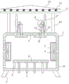
Fig. 1 is a schematic structural diagram of a power transformer case with good heat dissipation performance according to the present invention;
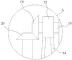
fig. 2 is the utility model provides a power transformer shell A part's that heat dispersion is good structural schematic.
In the figure: the fan comprises a shell 1, supporting legs 2, a dust-proof screen frame 3, a heat dissipation fan 4, a vertical plate 5, a heat dissipation supporting plate 6, heat dissipation fins 7, a lower air opening 8, an upper air opening 9, a supporting rod 10, a shielding plate 11, a buffer spring 12, a buffer plate 13, a support 14, a bearing seat 15, a rotating shaft 16, fan blades 17, a driving bevel gear 18, a rotating rod 19, a driven bevel gear 20 and fan blades 21.
Detailed Description
The technical solutions in the embodiments of the present invention will be described clearly and completely with reference to the accompanying drawings in the embodiments of the present invention, and it is obvious that the described embodiments are only some embodiments of the present invention, not all embodiments.
In the description of the present invention, it is to be understood that the terms "upper", "lower", "front", "rear", "left", "right", "top", "bottom", "inner", "outer", and the like indicate orientations or positional relationships based on the orientations or positional relationships shown in the drawings, and are only for convenience of description and simplicity of description, and do not indicate or imply that the device or element being referred to must have a particular orientation, be constructed and operated in a particular orientation, and therefore, should not be construed as limiting the present invention.
Referring to fig. 1-2, a power transformer shell that heat dispersion is good, including casing 1, the equal fixedly connected with landing leg 2 in bottom four corners department of casing 1, the equal fixedly connected with dust screen frame 3 of the relative both sides inner wall in left and right sides of casing 1, the inside fixedly connected with cooling fan 4 of dust screen frame 3, the same heat dissipation layer board 6 that is used for bearing the weight of installation electronic components of 5 fixedly connected with of riser that the bottom inner wall of casing 1 set up through two symmetries, the even fixedly connected with a plurality of radiating fin 7 of lower extreme of heat dissipation layer board 6, the lower extreme of radiating fin 7 runs through the bottom that stretches out casing 1, casing 1 has evenly seted up a plurality of lower wind gaps 8 near the lateral wall of bottom, a plurality of last wind gaps 9 have evenly been seted up to casing 1's upper end, the equal baffle 11 of the same fixedly connected with of upper end four corners department of casing 1 through bracing piece 10, the.
A plurality of ventilation holes corresponding to the cooling fan 4 are formed in the side wall of the shell 1, and the ventilation and heat dissipation of the cooling fan 4 can be guaranteed.
The upper end of casing 1 is through support 14 fixedly connected with bearing frame 15, it is connected with pivot 16 to rotate through ball bearing in the bearing frame 15, the one end fixedly connected with fan blade 17 of pivot 16, the other end fixedly connected with initiative helical gear 18 of pivot 16, trepanning and trepanning are seted up to the upper end of casing 1 and are rotated through ball bearing and be connected with bull stick 19, the upper end fixedly connected with of bull stick 19 and the driven helical gear 20 of initiative helical gear 18 meshing, the lower extreme of bull stick 19 stretches into in the casing 1 and fixedly connected with fan blade 21, when there is wind in casing 1 outside, wind-force drives fan blade 17 and rotates, and then drive initiative helical gear 18 and rotate, utilize the meshing of initiative helical gear 18 and driven helical gear 20 to drive bull stick 19 and rotate, and then drive fan blade 21 and rotate, can utilize natural wind-force to carry out the.
The specific materials of the heat dissipation supporting plate 6 and the heat dissipation fins 7 are copper, so that the heat dissipation performance of the structure is guaranteed.
The buffer plate 13 is of a triangular structure, so that sundries and rainwater can quickly fall out.
In the utility model, when in use, the heat dissipation fan 4 is arranged to quickly dissipate heat in the transformer casing, the dustproof screen frame 3 is arranged to avoid the problem that the heat dissipation fan 4 can convey external dust into the casing 1 to influence the normal use of the transformer, the electronic parts are arranged on the heat dissipation support plate 6, the heat dissipation support plate 6 can quickly guide away the heat generated by the electronic parts in the work, the heat can be quickly guided out of the casing through the heat dissipation fins 7, the power transformer has excellent heat dissipation performance, the power transformer can be reliably operated, the upper air inlet 9, the lower air inlet 8, the fan blades 17 and the fan blades 21 are arranged, when wind exists outside the casing 1, the wind power drives the fan blades 17 to rotate so as to drive the driving helical gear 18 to rotate, the rotating rod 19 is driven to rotate by the meshing action of the driving helical gear 18 and the driven helical gear 20, and then drive flabellum 21 and rotate, can utilize natural wind power to carry out the inside thermal treatment that dispels the heat of transformer housing 1, the lower wind gap 8 and the last wind gap 9 that set up can form the chimney effect, make hot-air walk quick discharge from the last wind gap, cold air gets into the replenishment from lower wind gap 8, utilize the natural energy can further promote the radiating efficiency to transformer housing 1 inside, and the cost is saved, through the bracing piece 10 that is equipped with, shielding plate 11, buffer spring 12 and buffer plate 13, when the transformer upper end receives external force striking, buffer plate 13 atress extrusion buffer spring 12, the resilience force that utilizes buffer spring 12 deformation to produce can carry out effectual protection to the transformer, safety protection nature is good.
The above, only be the concrete implementation of the preferred embodiment of the present invention, but the protection scope of the present invention is not limited thereto, and any person skilled in the art is in the technical scope of the present invention, according to the technical solution of the present invention and the utility model, the concept of which is equivalent to replace or change, should be covered within the protection scope of the present invention.
Claims (5)
1. A power transformer shell with good heat dissipation performance comprises a shell (1) and is characterized in that supporting legs (2) are fixedly connected to four corners of the bottom of the shell (1), dustproof net frames (3) are fixedly connected to inner walls of the left side and the right side of the shell (1), a heat dissipation fan (4) is fixedly connected to the inner portion of each dustproof net frame (3), a heat dissipation supporting plate (6) used for bearing and installing electronic parts is fixedly connected to the inner wall of the bottom of the shell (1) through two symmetrically arranged vertical plates (5), a plurality of heat dissipation fins (7) are uniformly and fixedly connected to the lower end of each heat dissipation supporting plate (6), the lower ends of the heat dissipation fins (7) penetrate through the bottom of the shell (1), a plurality of lower air openings (8) are uniformly formed in the side wall, close to the bottom, of the shell (1), a plurality of upper air openings (9) are uniformly formed in the upper end of, the upper end four corners department of casing (1) all through the same shielding plate (11) of bracing piece (10) fixedly connected with, the upper end of shielding plate (11) is through the same buffer board (13) of a plurality of buffer spring (12) fixedly connected with.
2. The power transformer casing with good heat dissipation performance according to claim 1, wherein a plurality of vent holes corresponding to the heat dissipation fan (4) are formed in the side wall of the casing (1).
3. The power transformer shell with good heat dissipation performance according to claim 1, wherein a bearing seat (15) is fixedly connected to the upper end of the shell (1) through a support (14), a rotating shaft (16) is rotatably connected to the inside of the bearing seat (15) through a ball bearing, a fan blade (17) is fixedly connected to one end of the rotating shaft (16), a driving helical gear (18) is fixedly connected to the other end of the rotating shaft (16), a sleeve hole is formed in the upper end of the shell (1), a rotating rod (19) is rotatably connected to the inside of the sleeve hole through a ball bearing, a driven helical gear (20) meshed with the driving helical gear (18) is fixedly connected to the upper end of the rotating rod (19), and the lower end of the rotating rod (19) extends into the shell (1) and is fixedly connected with the fan blade (21).
4. The power transformer shell with good heat dissipation performance according to claim 1, wherein the specific materials of the heat dissipation supporting plate (6) and the heat dissipation fins (7) are both copper.
5. The power transformer housing with good heat dissipation performance as recited in claim 1, wherein the buffer plate (13) is of a triangular structure.
Priority Applications (1)
| Application Number | Priority Date | Filing Date | Title |
|---|---|---|---|
| CN201921397238.7U CN210896852U (en) | 2019-08-27 | 2019-08-27 | Power transformer shell with good heat dissipation performance |
Applications Claiming Priority (1)
| Application Number | Priority Date | Filing Date | Title |
|---|---|---|---|
| CN201921397238.7U CN210896852U (en) | 2019-08-27 | 2019-08-27 | Power transformer shell with good heat dissipation performance |
Publications (1)
| Publication Number | Publication Date |
|---|---|
| CN210896852U true CN210896852U (en) | 2020-06-30 |
Family
ID=71317971
Family Applications (1)
| Application Number | Title | Priority Date | Filing Date |
|---|---|---|---|
| CN201921397238.7U Expired - Fee Related CN210896852U (en) | 2019-08-27 | 2019-08-27 | Power transformer shell with good heat dissipation performance |
Country Status (1)
| Country | Link |
|---|---|
| CN (1) | CN210896852U (en) |
Cited By (1)
| Publication number | Priority date | Publication date | Assignee | Title |
|---|---|---|---|---|
| CN112435833A (en) * | 2020-11-13 | 2021-03-02 | 广东电网有限责任公司 | Heat dissipation mechanism of power transformer |
-
2019
- 2019-08-27 CN CN201921397238.7U patent/CN210896852U/en not_active Expired - Fee Related
Cited By (2)
| Publication number | Priority date | Publication date | Assignee | Title |
|---|---|---|---|---|
| CN112435833A (en) * | 2020-11-13 | 2021-03-02 | 广东电网有限责任公司 | Heat dissipation mechanism of power transformer |
| CN112435833B (en) * | 2020-11-13 | 2021-10-01 | 广东电网有限责任公司 | A heat dissipation mechanism for a power transformer |
Similar Documents
| Publication | Publication Date | Title |
|---|---|---|
| CN208143074U (en) | A kind of spinning frame frequency converter cooling device | |
| CN210075805U (en) | Self-radiating structure of air conditioner control box | |
| CN216773933U (en) | Intelligent power distribution cabinet with optimized design | |
| CN112072823A (en) | High-efficient radiating switched reluctance drive arrangement | |
| CN213783903U (en) | Novel server cabinet for Internet of things | |
| CN211044111U (en) | Quick radiating computer machine case | |
| CN209981117U (en) | An air-cooled solid state relay | |
| CN221101825U (en) | Intelligent heat dissipation type electronic transformer | |
| CN214170735U (en) | Wind power generation tower cylinder structure with good heat dissipation effect | |
| CN208752893U (en) | A protection device for LED display | |
| CN216215301U (en) | Block terminal with heat abstractor | |
| CN216307599U (en) | High-power integrated form wisdom street lamp with heat radiation structure | |
| CN215170931U (en) | Fan energy-saving device | |
| CN204667280U (en) | A kind of notebook computer of high efficiency and heat radiation | |
| CN213690506U (en) | Artificial intelligence application service software development terminal | |
| CN213341363U (en) | Power distribution cabinet for easy heat dissipation and dust removal | |
| CN212573264U (en) | Outdoor display upper shell with heat dissipation and dust removal effects | |
| CN210348315U (en) | High heat dissipation computer display screen structure | |
| CN220823427U (en) | Radiator of electromechanical equipment | |
| CN210958117U (en) | Fixing device of frequency converter | |
| CN219081857U (en) | Energy-saving water pump with overheat protection mechanism | |
| CN222563344U (en) | Power distribution cabinet with excellent heat dissipation performance | |
| CN207519048U (en) | A kind of PTFE microwave circuits plate heat dissipating device | |
| CN216251861U (en) | Electric automation control's heat dissipation regulator cubicle | |
| CN115144629B (en) | An intelligent building energy consumption monitoring device that facilitates maintenance of internal components |
Legal Events
| Date | Code | Title | Description |
|---|---|---|---|
| GR01 | Patent grant | ||
| GR01 | Patent grant | ||
| CF01 | Termination of patent right due to non-payment of annual fee |
Granted publication date: 20200630 |
|
| CF01 | Termination of patent right due to non-payment of annual fee |