CN210893500U - Detection device for glass production - Google Patents
Detection device for glass production Download PDFInfo
- Publication number
- CN210893500U CN210893500U CN201921373450.XU CN201921373450U CN210893500U CN 210893500 U CN210893500 U CN 210893500U CN 201921373450 U CN201921373450 U CN 201921373450U CN 210893500 U CN210893500 U CN 210893500U
- Authority
- CN
- China
- Prior art keywords
- workstation
- splint
- workbench
- fixed mounting
- glass production
- Prior art date
- Legal status (The legal status is an assumption and is not a legal conclusion. Google has not performed a legal analysis and makes no representation as to the accuracy of the status listed.)
- Expired - Fee Related
Links
- 238000001514 detection method Methods 0.000 title claims abstract description 23
- 239000011521 glass Substances 0.000 title claims abstract description 23
- 238000004519 manufacturing process Methods 0.000 title claims abstract description 21
- 239000003381 stabilizer Substances 0.000 claims abstract description 5
- 244000309464 bull Species 0.000 claims abstract description 3
- 230000006978 adaptation Effects 0.000 claims description 6
- 230000008859 change Effects 0.000 claims description 5
- 230000000149 penetrating effect Effects 0.000 claims description 4
- 238000009434 installation Methods 0.000 claims description 3
- 238000009826 distribution Methods 0.000 claims description 2
- 238000007689 inspection Methods 0.000 claims 5
- 239000005341 toughened glass Substances 0.000 abstract description 31
- 230000000694 effects Effects 0.000 abstract description 6
- 206010044565 Tremor Diseases 0.000 abstract description 2
- 238000000034 method Methods 0.000 description 10
- 230000008569 process Effects 0.000 description 4
- 230000009471 action Effects 0.000 description 3
- 238000003825 pressing Methods 0.000 description 3
- 230000004075 alteration Effects 0.000 description 1
- 230000009286 beneficial effect Effects 0.000 description 1
- 230000007547 defect Effects 0.000 description 1
- 238000012986 modification Methods 0.000 description 1
- 230000004048 modification Effects 0.000 description 1
- 239000006058 strengthened glass Substances 0.000 description 1
- 238000006467 substitution reaction Methods 0.000 description 1
Images


Landscapes
- Re-Forming, After-Treatment, Cutting And Transporting Of Glass Products (AREA)
Abstract
The utility model relates to a toughened glass production and processing technology field just discloses a detection device for glass production, comprises a workbench, the equal fixed mounting in the left and right sides of workstation bottom has the stabilizer blade, the interior diapire fixed mounting of workstation has servo motor. This detection device is used in glass production, through starting servo motor, make the bull stick rotate, drive bevel gear and rotate, drive meshing gear through the meshing, make the threaded rod rotate, two movable loop bars receive the screw thread thrust and the reverse movement when the threaded rod rotates, thereby drive two splint and control on the workstation and remove, can control the distance between two splint, when needs carry out stress detection to toughened glass, only need to place toughened glass between two splint, through controlling servo motor, make two splint stabilize the toughened glass centre gripping on the workstation, effectively avoid toughened glass to place the shakiness on the workstation and lead to dropping, make equipment reach the effect that the security performance is high.
Description
Technical Field
The utility model relates to a toughened glass production and processing technology field specifically is a detection device is used in glass production.
Background
The toughened glass is glass with compressive stress on the surface, is also called strengthened glass, and is strengthened by adopting a toughening method.
The tempered glass stress detection device commonly used in the market at present generally has the defect of low safety performance, and the tempered glass is usually directly placed on a detection table and is not fixed, so that the tempered glass is easily dropped on the ground carelessly in the detection process, the glass is broken, the working efficiency is influenced, and the use requirement of people is not met, so that the detection device for glass production is provided to solve the problem.
SUMMERY OF THE UTILITY MODEL
Technical problem to be solved
The utility model provides a to prior art's is not enough, the utility model provides a detection device is used in glass production possesses advantages such as security performance height, has solved and has commonly used in toughened glass stress detection device in the existing market and generally has had the lower shortcoming of security performance, directly places toughened glass on examining test table usually, does not fix it, leads to falling it on the ground carelessly at the in-process that detects very easily like this, leads to glass broken, influences work efficiency, unsatisfied people's user demand's problem.
(II) technical scheme
For the purpose that realizes above-mentioned security performance is high, the utility model provides a following technical scheme: a detection device for glass production comprises a workbench, wherein support legs are fixedly mounted on the left side and the right side of the bottom of the workbench respectively, a servo motor is fixedly mounted on the inner bottom wall of the workbench, a rotating rod with one end movably connected with the workbench is fixedly mounted on an output shaft of the servo motor, a bevel gear is fixedly mounted on the outer side of the rotating rod, a threaded rod is movably connected between the left side wall and the right side wall of an inner cavity of the workbench, a meshing gear with the bevel gear is fixedly mounted on the outer side of the threaded rod, movable sleeve rods are movably mounted on the left side and the right side of the outer side of the threaded rod respectively, a clamping plate with one end penetrating through and extending to the outer side of the workbench and movably connected with the workbench is fixedly mounted on the top of the clamping plate, a rotating ring is movably mounted on the top of the clamping plate, a threaded thin rod with one end penetrating through and extending to the bottom of the, the utility model discloses a clamp plate, including clamp plate, clamp plate top, fixed mounting, workstation top, fixed mounting, the top fixed mounting of screw thread thin rod has the spacing ring, the bottom fixed mounting of screw thread thin rod has one end to run through and extend to splint inner chamber and with splint swing joint's clamp plate, two the equal fixed mounting in one side that the clamp plate was carried on the back mutually has one end and splint swing joint's slider, the equal fixed mounting in the left and right sides at clamp plate top has one end and fixed plate fixed connection's telescopic link, the back fixed mounting at workstation top has the connecting rod, the top of workstation.
Preferably, the left and right sides at workstation top has all seted up the spout, and spout and splint looks adaptation, servo motor's bottom fixed mounting has one end and workstation fixed connection's motor cabinet.
Preferably, the quantity of stabilizer blade is two, and two stabilizer blades are the symmetric distribution with the perpendicular bisector of workstation, the connecting rod is ninety degrees vertical mount with the workstation.
Preferably, threaded holes are formed in one opposite side of each of the two movable sleeve rods and are matched with the threaded rods, and the thread directions of the threaded holes formed in the two movable sleeve rods are opposite.
Preferably, two the draw-in groove has all been seted up to the relative one side of splint, and draw-in groove and slider looks adaptation, the bull stick is ninety degrees perpendicular installation with the workstation.
Preferably, the bottom fixed mounting of swivel has the bearing, and the swivel passes through bearing and fixed plate swing joint, the quantity of telescopic link is four.
(III) advantageous effects
Compared with the prior art, the utility model provides a detection device is used in glass production possesses following beneficial effect:
1. the detection device for glass production is characterized in that a servo motor is arranged, the servo motor is started, a rotating rod is rotated to drive a bevel gear to rotate, a meshing gear is driven to rotate through meshing, a threaded rod is rotated, threaded holes matched with the threaded rod are formed in two movable sleeve rods, the thread directions of the two threaded holes are opposite, when the threaded rod rotates, the two movable sleeve rods move in the reverse direction under the action of the thread thrust generated when the threaded rod rotates, so that the two clamping plates are driven to move left and right on a workbench, the distance between the two clamping plates can be controlled, when the stress detection of toughened glass is required, only the toughened glass needs to be placed between the two clamping plates, the toughened glass is clamped and fixed on the workbench by the two clamping plates through controlling the servo motor, the phenomenon that the toughened glass is placed unstably on the workbench and falls off is effectively avoided, and the equipment achieves the effect of high, and the structure is simple, the use is convenient, and the working efficiency is improved.
2. This detection device is used in glass production through be provided with on the change with the screw thread through-hole of the thin pole looks adaptation of screw thread, makes when rotating the change, and the thin pole of screw thread receives screw thread thrust when the change rotates and reciprocates, can further compress tightly toughened glass, improve equipment's security performance, more satisfy the demand that people used.
Drawings
FIG. 1 is a schematic structural view of the present invention;
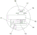
FIG. 2 is an enlarged view of the point A in FIG. 1 according to the present invention;
fig. 3 is a side view of the overall structure of the present invention.
In the figure: the device comprises a connecting rod 1, a stress test frame 2, a workbench 3, a supporting leg 4, a movable sleeve rod 5, a threaded rod 6, a meshing gear 7, a rotating rod 8, a conical gear 9, a servo motor 10, a clamping plate 11, a sliding block 12, a pressing plate 13, a telescopic rod 14, a fixed plate 15, a rotating ring 16, a threaded thin rod 17 and a limiting ring 18.
Detailed Description
The technical solutions in the embodiments of the present invention will be described clearly and completely with reference to the accompanying drawings in the embodiments of the present invention, and it is obvious that the described embodiments are only some embodiments of the present invention, not all embodiments. Based on the embodiments in the present invention, all other embodiments obtained by a person skilled in the art without creative work belong to the protection scope of the present invention.
Referring to fig. 1-3, a detection device for glass production comprises a workbench 3, chutes are formed on the left and right sides of the top of the workbench 3, the chutes are matched with clamping plates 11, support legs 4 are fixedly mounted on the left and right sides of the bottom of a motor base workbench 3, one end of each support leg 4 is fixedly connected with the workbench 3, the two support legs 4 are symmetrically distributed on the perpendicular bisector of the workbench 3, a connecting rod 1 is vertically mounted at ninety degrees with the workbench 3, a servo motor 10 is fixedly mounted on the inner bottom wall of the workbench 3, the servo motor 10 is started by arranging the servo motor 10, a rotating rod 8 is rotated to drive a bevel gear 9 to rotate, a meshing gear 7 is driven to rotate by meshing, a threaded rod 6 is rotated, threaded holes matched with the threaded rod 6 are formed in two movable sleeve rods 5, and the thread directions of the two threaded holes are opposite, when the threaded rod 6 rotates, the two movable loop bars 5 are pushed by the thread when the threaded rod 6 rotates and move reversely, so as to drive the two clamping plates 11 to move left and right on the workbench 3, and the distance between the two clamping plates 11 can be controlled, when the stress detection is needed to be carried out on the toughened glass, the toughened glass is only needed to be placed between the two clamping plates 11, the type of the servo motor 10 can be PLX-60 by controlling the servo motor 10, so that the toughened glass is clamped and fixed on the workbench 3 by the two clamping plates 11, the falling caused by the unstable placement of the toughened glass on the workbench 3 is effectively avoided, the equipment achieves the effect of high safety, the structure is simple, the use is convenient, the working efficiency is improved, the output shaft of the servo motor 10 is fixedly provided with the rotating rod 8 of which one end is movably connected with the workbench 3, the outer side of the rotating rod, a threaded rod 6 is movably connected between the left side wall and the right side wall of the inner cavity of the workbench 3, a meshing gear 7 with one end meshed with a bevel gear 9 is fixedly arranged on the outer side of the threaded rod 6, movable sleeve rods 5 are movably arranged on the left end and the right end of the outer side of the threaded rod 6, threaded holes are respectively arranged on the opposite sides of the two movable sleeve rods 5 and are matched with the threaded rod 6, the thread directions of the threaded holes arranged on the two movable sleeve rods 5 are opposite, a clamping plate 11 with one end penetrating and extending to the outer side of the workbench 3 and movably connected with the workbench 3 is fixedly arranged on the top of each movable sleeve rod 5, clamping grooves are respectively arranged on the opposite sides of the two clamping plates 11 and are matched with a sliding block 12, the rotating rod 8 and the workbench 3 are vertically arranged at ninety degrees, a fixing plate 15 is fixedly arranged on the top of each clamping plate 11, a rotating ring 16 is, the rotating ring 16 is more convenient to rotate and convenient to use by arranging the rotating handle, the toughened glass can be further compressed by arranging the threaded through hole matched with the threaded thin rod 17 on the rotating ring 16, when the rotating ring 16 is rotated, the threaded thin rod 17 moves up and down under the action of the threaded thrust generated when the rotating ring 16 rotates, the safety performance of the equipment is improved, and the use requirement of people is further met, the bottom of the rotating ring 16 is fixedly provided with a bearing, the rotating ring 16 is movably connected with the fixed plate 15 through the bearing, the number of the telescopic rods 14 is four, the top of the rotating ring 16 is movably provided with the threaded thin rod 17, one end of the threaded thin rod 17 penetrates through and extends to the bottom of the rotating ring 16, the top of the threaded thin rod 17 is fixedly provided with a limiting ring 18, the bottom of the threaded thin rod 17 is fixedly provided with a pressing plate 13, one end of the pressing plate 13 penetrates through and extends to the inner cavity of the clamping plate 11 and is movably connected with the clamping plate 11, the equal fixed mounting in the left and right sides at clamp plate 13 top has one end and fixed plate 15 fixed connection's telescopic link 14, telescopic link 14 comprises dead lever and carriage release lever, the bottom of carriage release lever run through and extend to the inner chamber of dead lever and with dead lever swing joint, through setting up telescopic link 14, it is fixed more steady with toughened glass to make clamp plate 13, the back fixed mounting at 3 tops of workstation has connecting rod 1, there is stress test frame 2 at the top of workstation 3 through connecting rod 1 fixed mounting.
When the device is used, the distance between the two clamping plates 11 can be flexibly controlled only by controlling the rotation of the servo motor 10, the toughened glass is fixed on the workbench 3, the device achieves the effect of high safety performance, the structure is simple, the use is convenient, and the working efficiency is improved.
In conclusion, the detection device for glass production is provided with the servo motor 10, the servo motor 10 is started, the rotating rod 8 is rotated to drive the bevel gear 9 to rotate, the meshing gear 7 is driven to rotate through meshing, the threaded rod 6 is driven to rotate, the threaded holes matched with the threaded rod 6 are formed in the two movable sleeve rods 5, the thread directions of the two threaded holes are opposite, when the threaded rod 6 rotates, the two movable sleeve rods 5 move in opposite directions under the action of the thread thrust generated when the threaded rod 6 rotates, the two clamping plates 11 are driven to move left and right on the workbench 3, the distance between the two clamping plates 11 can be controlled, when stress detection needs to be carried out on toughened glass, only the toughened glass needs to be placed between the two clamping plates 11, the type of the servo motor 10 can be PLX-60 through controlling the servo motor 10, so that the two clamping plates 11 clamp the toughened glass firmly on the workbench 3, effectively avoid toughened glass to place the shakiness on workstation 3 and lead to falling, make equipment reach the effect that the security performance is high, and simple structure, convenient to use has improved work efficiency.
And, through be provided with the screw thread through-hole with screw thread pin 17 looks adaptation on swivel 16, it makes when rotating swivel 16, screw thread pin 17 receives the screw thread thrust when swivel 16 rotates and reciprocates, can further compress tightly toughened glass, improve equipment's security performance, more satisfy the demand that people used, it generally has the shortcoming that security performance is lower to have solved commonly used in toughened glass stress detection device on the existing market, it is direct to place toughened glass on detecting the platform usually, do not fix it, very easily lead to falling it on the ground carelessly in the in-process that detects like this, lead to glass breakage, influence work efficiency, unsatisfied people's user demand's problem.
It is to be noted that the terms "comprises," "comprising," or any other variation thereof, are intended to cover a non-exclusive inclusion, such that a process, method, article, or apparatus that comprises a list of elements does not include only those elements but may include other elements not expressly listed or inherent to such process, method, article, or apparatus. Without further limitation, an element defined by the phrase "comprising an … …" does not exclude the presence of other identical elements in a process, method, article, or apparatus that comprises the element.
Although embodiments of the present invention have been shown and described, it will be appreciated by those skilled in the art that changes, modifications, substitutions and alterations can be made in these embodiments without departing from the principles and spirit of the invention, the scope of which is defined in the appended claims and their equivalents.
Claims (6)
1. The utility model provides a detection device is used in glass production, includes workstation (3), its characterized in that: the all-in-one machine tool is characterized in that support legs (4) are fixedly mounted on the left side and the right side of the bottom of the workbench (3), a servo motor (10) is fixedly mounted on the inner bottom wall of the workbench (3), a rotating rod (8) with one end movably connected with the workbench (3) is fixedly mounted on an output shaft of the servo motor (10), a bevel gear (9) is fixedly mounted on the outer side of the rotating rod (8), a threaded rod (6) is movably connected between the left side wall and the right side wall of the inner cavity of the workbench (3), a meshing gear (7) with one end meshed with the bevel gear (9) is fixedly mounted on the outer side of the threaded rod (6), a movable sleeve rod (5) is movably mounted on the left end and the right end of the outer side of the threaded rod (6), and a clamping plate (11) with one end penetrating through and extending to the outer side of the workbench (, the top fixed mounting of splint (11) has fixed plate (15), the top movable mounting of fixed plate (15) has swivel (16), the top movable mounting of swivel (16) has screw thread pin (17) that one end runs through and extends to swivel (16) bottom, the top fixed mounting of screw thread pin (17) has spacing ring (18), the bottom fixed mounting of screw thread pin (17) has clamp plate (13) that one end runs through and extends to splint (11) inner chamber and with splint (11) swing joint, two one side that clamp plate (13) were carried on the back mutually all fixed mounting have one end and splint (11) swing joint's slider (12), the equal fixed mounting in the left and right sides at clamp plate (13) top has one end and fixed plate (15) fixed connection's telescopic link (14), the back fixed mounting at workstation (3) top has connecting rod (1), the top of the workbench (3) is fixedly provided with a stress test frame (2) through a connecting rod (1).
2. The inspection device for glass production according to claim 1, wherein: the left and right sides at workstation (3) top has all seted up the spout, and spout and splint (11) looks adaptation, the bottom fixed mounting of servo motor (10) has one end and workstation (3) fixed connection's motor cabinet.
3. The inspection device for glass production according to claim 1, wherein: the quantity of stabilizer blade (4) is two, and two stabilizer blades (4) are the symmetric distribution with the perpendicular bisector of workstation (3), connecting rod (1) is the perpendicular installation of ninety degrees with workstation (3).
4. The inspection device for glass production according to claim 1, wherein: threaded holes are formed in one side, opposite to the movable sleeve rods (5), of each of the two movable sleeve rods, the threaded holes are matched with the threaded rods (6), and the thread directions of the threaded holes formed in the two movable sleeve rods (5) are opposite.
5. The inspection device for glass production according to claim 1, wherein: two the draw-in groove has all been seted up to splint (11) relative one side, and draw-in groove and slider (12) looks adaptation, bull stick (8) are ninety degrees perpendicular installation with workstation (3).
6. The inspection device for glass production according to claim 1, wherein: the bottom fixed mounting of change (16) has the bearing, and change (16) through bearing and fixed plate (15) swing joint, the quantity of telescopic link (14) is four.
Priority Applications (1)
| Application Number | Priority Date | Filing Date | Title |
|---|---|---|---|
| CN201921373450.XU CN210893500U (en) | 2019-08-22 | 2019-08-22 | Detection device for glass production |
Applications Claiming Priority (1)
| Application Number | Priority Date | Filing Date | Title |
|---|---|---|---|
| CN201921373450.XU CN210893500U (en) | 2019-08-22 | 2019-08-22 | Detection device for glass production |
Publications (1)
| Publication Number | Publication Date |
|---|---|
| CN210893500U true CN210893500U (en) | 2020-06-30 |
Family
ID=71335604
Family Applications (1)
| Application Number | Title | Priority Date | Filing Date |
|---|---|---|---|
| CN201921373450.XU Expired - Fee Related CN210893500U (en) | 2019-08-22 | 2019-08-22 | Detection device for glass production |
Country Status (1)
| Country | Link |
|---|---|
| CN (1) | CN210893500U (en) |
Cited By (6)
| Publication number | Priority date | Publication date | Assignee | Title |
|---|---|---|---|---|
| CN112378370A (en) * | 2020-12-14 | 2021-02-19 | 澧县澧水明珠钢化玻璃有限公司 | Toughened glass surface flatness detection device |
| CN113109132A (en) * | 2021-04-09 | 2021-07-13 | 安徽荣春玻璃科技有限公司 | High borosilicate fire prevention glass intensity detection device |
| CN113199573A (en) * | 2021-03-28 | 2021-08-03 | 郝崑 | Numerical control groove broaching device for furniture board machining |
| CN113267457A (en) * | 2021-05-17 | 2021-08-17 | 泰辉兴科技(厦门)有限公司 | 3D glass vision measurement workbench |
| CN114136515A (en) * | 2021-10-25 | 2022-03-04 | 湖北光锐鑫光电科技有限公司 | Optical glass stress measuring device and measuring method thereof |
| CN116399287A (en) * | 2023-06-08 | 2023-07-07 | 山东华美新材料科技股份有限公司 | Silicon carbide uniform Wen Banping area degree detection device for liquid crystal glass substrate manufacturing process |
-
2019
- 2019-08-22 CN CN201921373450.XU patent/CN210893500U/en not_active Expired - Fee Related
Cited By (8)
| Publication number | Priority date | Publication date | Assignee | Title |
|---|---|---|---|---|
| CN112378370A (en) * | 2020-12-14 | 2021-02-19 | 澧县澧水明珠钢化玻璃有限公司 | Toughened glass surface flatness detection device |
| CN113199573A (en) * | 2021-03-28 | 2021-08-03 | 郝崑 | Numerical control groove broaching device for furniture board machining |
| CN113109132A (en) * | 2021-04-09 | 2021-07-13 | 安徽荣春玻璃科技有限公司 | High borosilicate fire prevention glass intensity detection device |
| CN113267457A (en) * | 2021-05-17 | 2021-08-17 | 泰辉兴科技(厦门)有限公司 | 3D glass vision measurement workbench |
| CN113267457B (en) * | 2021-05-17 | 2024-03-19 | 泰辉兴科技(厦门)有限公司 | 3D glass vision measurement workbench |
| CN114136515A (en) * | 2021-10-25 | 2022-03-04 | 湖北光锐鑫光电科技有限公司 | Optical glass stress measuring device and measuring method thereof |
| CN116399287A (en) * | 2023-06-08 | 2023-07-07 | 山东华美新材料科技股份有限公司 | Silicon carbide uniform Wen Banping area degree detection device for liquid crystal glass substrate manufacturing process |
| CN116399287B (en) * | 2023-06-08 | 2023-08-25 | 山东华美新材料科技股份有限公司 | Silicon carbide uniform Wen Banping area degree detection device for liquid crystal glass substrate manufacturing process |
Similar Documents
| Publication | Publication Date | Title |
|---|---|---|
| CN211614374U (en) | High accuracy multi-spindle drilling machine convenient to work piece is fixed | |
| CN107962633A (en) | A kind of building board cutting device that can adjust thickness | |
| CN209557988U (en) | A kind of hanging support device of patch mural circle | |
| CN108381221B (en) | Large-caliber special pipeline processing device | |
| CN210453276U (en) | A cutting device for stone processing | |
| CN209902668U (en) | Angle adjusting mechanism of steel bar end face cutting device | |
| CN217529286U (en) | Metal plate drilling device | |
| CN107984510B (en) | Calibration counterpoint formula board cutting machine | |
| CN218313951U (en) | A slicer for easy replacement of cutting blades | |
| CN215146574U (en) | Automatic nut feeding equipment | |
| CN210361991U (en) | Graphite round bar rotary cutting processing platform | |
| CN211276793U (en) | Cutting equipment for processing cylindrical rod | |
| CN210306011U (en) | Raw materials cutting device is used in aluminum mould board production | |
| CN212239490U (en) | Lifting working frame of self-adaptive spark machine | |
| CN210968566U (en) | Turnover mechanism for processing artware | |
| CN222060586U (en) | A cut-proof artificial board cutting device | |
| CN221338991U (en) | Hydraulic engineering construction building materials cutting machine | |
| CN222903946U (en) | A fixed tool for bracket processing | |
| CN209503574U (en) | A kind of electric motor end cap milling inclined-plane horizontal-vertical double-purpose universal fixture | |
| CN220093699U (en) | Screw machine convenient to level | |
| CN221720331U (en) | Automatic overturning platform for curtain wall | |
| CN221455172U (en) | Cleaning structure and weight plate processing drilling device | |
| CN112845943A (en) | A rectangular iron plate rounding equipment for hardware processing | |
| CN211362650U (en) | Novel cutting equipment for ceramic packaging raw material | |
| CN218904704U (en) | High-precision full-automatic chamfering machine |
Legal Events
| Date | Code | Title | Description |
|---|---|---|---|
| GR01 | Patent grant | ||
| GR01 | Patent grant | ||
| CF01 | Termination of patent right due to non-payment of annual fee | ||
| CF01 | Termination of patent right due to non-payment of annual fee |
Granted publication date: 20200630 Termination date: 20210822 |