CN210891382U - An LED photovoltaic integrated lighting device - Google Patents
An LED photovoltaic integrated lighting device Download PDFInfo
- Publication number
- CN210891382U CN210891382U CN201921521103.7U CN201921521103U CN210891382U CN 210891382 U CN210891382 U CN 210891382U CN 201921521103 U CN201921521103 U CN 201921521103U CN 210891382 U CN210891382 U CN 210891382U
- Authority
- CN
- China
- Prior art keywords
- cover
- solar photovoltaic
- led
- fixing plate
- led lamp
- Prior art date
- Legal status (The legal status is an assumption and is not a legal conclusion. Google has not performed a legal analysis and makes no representation as to the accuracy of the status listed.)
- Active
Links
- 230000001681 protective effect Effects 0.000 claims abstract description 22
- 230000017525 heat dissipation Effects 0.000 claims abstract description 16
- 238000010248 power generation Methods 0.000 claims abstract description 11
- 238000009423 ventilation Methods 0.000 claims description 3
- 238000006243 chemical reaction Methods 0.000 abstract description 4
- 230000005611 electricity Effects 0.000 abstract description 3
- 230000003760 hair shine Effects 0.000 abstract description 2
- 238000009434 installation Methods 0.000 abstract 1
- 230000000694 effects Effects 0.000 description 4
- 238000012986 modification Methods 0.000 description 2
- 230000004048 modification Effects 0.000 description 2
- 230000009286 beneficial effect Effects 0.000 description 1
- 230000007547 defect Effects 0.000 description 1
- 238000004134 energy conservation Methods 0.000 description 1
- 238000005265 energy consumption Methods 0.000 description 1
- 238000005516 engineering process Methods 0.000 description 1
- 230000007613 environmental effect Effects 0.000 description 1
- 238000000034 method Methods 0.000 description 1
- 238000013082 photovoltaic technology Methods 0.000 description 1
- 238000003466 welding Methods 0.000 description 1
Images


Landscapes
- Arrangement Of Elements, Cooling, Sealing, Or The Like Of Lighting Devices (AREA)
Abstract
本实用新型提供一种LED光伏一体照明装置,包括安装板、连接杆和防护网罩;所述安装板的底部通过一组连接杆与太阳能光伏罩的顶部固定连接;所述太阳能光伏罩的底部通过三根竖杆与LED灯固定板固定连接。太阳能光伏罩的设置,有利于提高使用的安全性,本装置在使用时可在LED灯固定板顶部的凹槽中安装光伏发电的配套设备,在白天阳光照射时太阳能光伏罩会发出电量经过转化后储存,太阳能光伏罩因为将LED灯固定板的顶部和外侧全部包裹在内,所以可以起到保护灯体和防止雨水接触内部线路的作用,而且内部发出的热量可透过防护网罩上的散热孔并通过LED灯固定板和太阳能光伏罩之间的缝隙向外散出,提高散热效率,同时防护网罩还能防止发电设备向外落出。
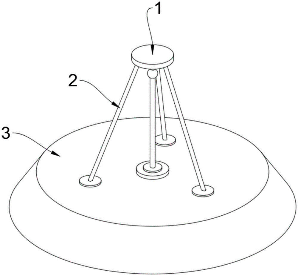
The utility model provides an LED photovoltaic integrated lighting device, comprising a mounting plate, a connecting rod and a protective net cover; the bottom of the mounting plate is fixedly connected with the top of the solar photovoltaic cover through a set of connecting rods; the bottom of the solar photovoltaic cover It is fixedly connected to the LED lamp fixing plate through three vertical rods. The installation of the solar photovoltaic cover is conducive to improving the safety of use. When the device is in use, photovoltaic power generation equipment can be installed in the groove on the top of the LED lamp fixing plate. When the sun shines during the day, the solar photovoltaic cover will emit electricity after conversion. After storage, the solar photovoltaic cover wraps the top and outer sides of the LED lamp fixing plate, so it can protect the lamp body and prevent rainwater from contacting the internal circuit, and the heat emitted from the inside can pass through the protective net cover. The heat dissipation holes radiate outward through the gap between the LED lamp fixing plate and the solar photovoltaic cover to improve the heat dissipation efficiency, and at the same time, the protective net cover can also prevent the power generation equipment from falling out.
Description
技术领域technical field
本实用新型属于LED照明技术领域,更具体地说,特别涉及一种LED光伏一体照明装置。The utility model belongs to the technical field of LED lighting, and more particularly, particularly relates to an LED photovoltaic integrated lighting device.
背景技术Background technique
由于太阳能光伏组件(简称光伏组件)可以提供清洁的绿色电力,一直以来被认为是能源革命的一个重要战场。将光伏组件应用到寿命长、能耗低的LED照明上则成为了21世纪以科技发展来实现节能环保的重要典范。将光伏技术与LED照明技术结合应用实现无需外加电源的照明系统有着广泛的应用前景,可应用于道路照明、农田作业照明、景观照明等领域。这种室外的照明系统对照明有时间应用的特性,大多是在夜间无日照的情况下使用。Since solar photovoltaic modules (referred to as photovoltaic modules) can provide clean green power, it has always been considered an important battlefield in the energy revolution. The application of photovoltaic modules to LED lighting with long life and low energy consumption has become an important model for realizing energy conservation and environmental protection through technological development in the 21st century. The combination of photovoltaic technology and LED lighting technology to achieve a lighting system that does not require external power has a wide range of application prospects, which can be applied to road lighting, farmland lighting, landscape lighting and other fields. This outdoor lighting system has the characteristics of time application to lighting, and is mostly used at night without sunlight.
例如申请号为201920154924.5的专利,公开了一种LED户外照明太阳能光伏板,包括安装底座、机壳、保护壳、光伏板、避雷针、蓄电池、电机、散热孔、安装螺孔、合页和凸环,安装底座顶部通过焊接固定有机壳,安装板顶部中心通过螺栓固定安装有电机,转轴的底端竖直固定连接在电机的输出轴上,转轴的顶端穿过机壳与保护壳顶部内壁固定连接,保护壳的侧面竖直安装固定有避雷针,支撑板的顶部通过螺栓固定安装有光伏板,电池仓设有蓄电池,蓄电池通过螺栓固定安装在机壳的底部内壁,机壳的侧壁底部开设有散热孔,该实用新型能够调整光伏板的垂直方向角度和水平方向上角度,最大化的提高对太阳能的转化利用效率,在位置较高的地方安装使用时,可以通过避雷针达到防雷的效果。For example, the patent application number 201920154924.5 discloses an LED outdoor lighting solar photovoltaic panel, including a mounting base, a chassis, a protective shell, a photovoltaic panel, a lightning rod, a battery, a motor, a heat dissipation hole, a mounting screw hole, a hinge and a convex ring , the top of the mounting base is fixed to the casing by welding, the center of the top of the mounting plate is fixed with the motor by bolts, the bottom end of the rotating shaft is vertically fixed and connected to the output shaft of the motor, and the top of the rotating shaft passes through the casing and is fixed to the top inner wall of the protective shell Connection, the side of the protective shell is vertically installed and fixed with a lightning rod, the top of the support plate is fixed with a photovoltaic panel by bolts, the battery compartment is provided with a battery, the battery is fixed on the bottom inner wall of the casing by bolts, and the bottom of the side wall of the casing is opened With heat dissipation holes, the utility model can adjust the vertical angle and horizontal angle of the photovoltaic panel to maximize the conversion and utilization efficiency of solar energy. When installed in a high position, the lightning rod can be used to achieve the effect of lightning protection. .
基于上述检索发现,上述专利同时结合现有技术中的多数光伏一体照明装置,其在使用时存在以下问题:现在的光伏一体照明装置虽然增加了光伏发电设备,但是光伏组部分设备是直接包裹在内侧的,散热只能依靠散热片和风扇,散热效果较差,侧面设置的开口容易让雨水接触造成线路故障,并且灯体顶部的保护结构也较少。Based on the above search, it is found that the above patent is combined with most of the photovoltaic integrated lighting devices in the prior art, which has the following problems in use: although the current photovoltaic integrated lighting device has added photovoltaic power generation equipment, some equipment of the photovoltaic group is directly wrapped in the On the inner side, heat dissipation can only rely on heat sinks and fans, and the heat dissipation effect is poor. The openings on the side are prone to rainwater contact and cause circuit failures, and there are fewer protective structures on the top of the lamp body.
于是,有鉴于此,针对现有的结构及缺失予以研究改良,提供一种LED光伏一体照明装置,以期达到更具有更加实用价值性的目的。Therefore, in view of this, the existing structure and defects are studied and improved, and an LED photovoltaic integrated lighting device is provided, in order to achieve a more practical purpose.
实用新型内容Utility model content
为了解决上述技术问题,本实用新型提供一种LED光伏一体照明装置,以解决现在的光伏一体照明装置虽然增加了光伏发电设备,但是光伏组部分设备是直接包裹在内侧的,散热只能依靠散热片和风扇,散热效果较差,侧面设置的开口容易让雨水接触造成线路故障,并且灯体顶部的保护结构也较少的问题。In order to solve the above technical problems, the utility model provides an LED photovoltaic integrated lighting device, so as to solve the problem that although photovoltaic power generation equipment is added to the current photovoltaic integrated lighting device, part of the photovoltaic group equipment is directly wrapped inside, and heat dissipation can only rely on heat dissipation The heat dissipation effect is poor, the openings on the side are easy to let rainwater contact and cause circuit failure, and there are fewer problems with the protective structure on the top of the lamp body.
本实用新型LED光伏一体照明装置的目的与功效,由以下具体技术手段所达成:The purpose and effect of the LED photovoltaic integrated lighting device of the present utility model are achieved by the following specific technical means:
一种LED光伏一体照明装置,包括安装板、连接杆、太阳能光伏罩、LED灯固定板、LED灯和防护网罩;所述安装板的底部通过一组连接杆与太阳能光伏罩的顶部固定连接;所述太阳能光伏罩的底部通过三根竖杆与LED灯固定板固定连接;所述LED灯固定板的底部内侧固定安装有一个LED灯;所述LED灯固定板的顶部还固定设置有一组防护网罩。An LED photovoltaic integrated lighting device, comprising a mounting plate, a connecting rod, a solar photovoltaic cover, an LED lamp fixing plate, an LED lamp and a protective net cover; the bottom of the mounting plate is fixedly connected to the top of the solar photovoltaic cover through a set of connecting rods The bottom of the solar photovoltaic cover is fixedly connected with the LED lamp fixing plate through three vertical rods; an LED lamp is fixedly installed on the inner side of the bottom of the LED lamp fixing plate; the top of the LED lamp fixing plate is also fixedly provided with a set of protection grille.
进一步的,所述太阳能光伏罩的外侧为圆台形下翻结构,底部为全开式圆形开口。Further, the outer side of the solar photovoltaic cover is a truncated downturned structure, and the bottom is a fully open circular opening.
进一步的,所述LED灯固定板的顶部设置有一个凹槽,使用时可以安装光伏发电的配套设备。Further, the top of the LED lamp fixing plate is provided with a groove, which can be used to install photovoltaic power generation supporting equipment.
进一步的,所述防护网罩上设置有若干透气散热网孔,且防护网罩的高度与太阳能光伏罩和LED灯固定板之间的竖杆高度相同。Further, the protective net cover is provided with several ventilation and heat dissipation mesh holes, and the height of the protective net cover is the same as the height of the vertical rod between the solar photovoltaic cover and the LED lamp fixing plate.
进一步的,所述LED灯固定板的直径小于太阳能光伏罩的顶部最小部分的内径。Further, the diameter of the LED lamp fixing plate is smaller than the inner diameter of the smallest part of the top of the solar photovoltaic cover.
与现有技术相比,本实用新型具有如下有益效果:Compared with the prior art, the utility model has the following beneficial effects:
太阳能光伏罩的设置,有利于提高使用的安全性,本装置在使用时可在LED灯固定板顶部的凹槽中安装光伏发电的配套设备,在白天阳光照射时太阳能光伏罩会发出电量经过转化后储存,太阳能光伏罩因为将LED灯固定板的顶部和外侧全部包裹在内,所以可以起到保护灯体和防止雨水接触内部线路的作用,而且内部发出的热量可透过防护网罩上的散热孔并通过LED灯固定板和太阳能光伏罩之间的缝隙向外散出,提高散热效率,同时防护网罩还能防止发电设备向外落出。The setting of the solar photovoltaic cover is conducive to improving the safety of use. When the device is in use, the photovoltaic power generation equipment can be installed in the groove on the top of the LED lamp fixing plate. When the sun shines during the day, the solar photovoltaic cover will emit electricity after conversion After storage, the solar photovoltaic cover wraps the top and outer sides of the LED lamp fixing plate, so it can protect the lamp body and prevent rainwater from contacting the internal circuit, and the heat emitted from the inside can pass through the protective net cover. The heat dissipation holes radiate outward through the gap between the LED lamp fixing plate and the solar photovoltaic cover to improve the heat dissipation efficiency. At the same time, the protective mesh cover can also prevent the power generation equipment from falling out.
附图说明Description of drawings
图1是本实用新型的俯轴侧结构示意图。FIG. 1 is a schematic view of the structure of the lower axis side of the present invention.
图2是本实用新型的仰轴侧结构示意图。FIG. 2 is a schematic view of the structure of the elevation axis side of the present invention.
图3是本实用新型剖切后的轴侧结构示意图。FIG. 3 is a schematic view of the shaft side structure of the utility model after cutting.
图4是本实用新型剖切后的主视结构示意图。FIG. 4 is a schematic view of the front structure of the utility model after cutting.
图中,部件名称与附图编号的对应关系为:In the figure, the corresponding relationship between component names and drawing numbers is:
1、安装板;2、连接杆;3、太阳能光伏罩;4、LED灯固定板;5、LED灯;6、防护网罩。1. Mounting plate; 2. Connecting rod; 3. Solar photovoltaic cover; 4. LED light fixing plate; 5. LED light; 6. Protective mesh cover.
具体实施方式Detailed ways
下面结合附图和实施例对本实用新型的实施方式作进一步详细描述。以下实施例用于说明本实用新型,但不能用来限制本实用新型的范围。The embodiments of the present utility model will be described in further detail below with reference to the accompanying drawings and examples. The following examples are used to illustrate the present invention, but cannot be used to limit the scope of the present invention.
在本实用新型的描述中,除非另有说明,“多个”的含义是两个或两个以上;术语“上”、“下”、“左”、“右”、“内”、“外”、“前端”、“后端”、“头部”、“尾部”等指示的方位或位置关系为基于附图所示的方位或位置关系,仅是为了便于描述本实用新型和简化描述,而不是指示或暗示所指的装置或元件必须具有特定的方位、以特定的方位构造和操作,因此不能理解为对本实用新型的限制。此外,术语“第一”、“第二”、“第三”等仅用于描述目的,而不能理解为指示或暗示相对重要性。In the description of the present utility model, unless otherwise specified, "multiple" means two or more; the terms "upper", "lower", "left", "right", "inner", "outer" ", "front end", "rear end", "head", "tail" and other indications of orientation or positional relationship are based on the orientation or positional relationship shown in the accompanying drawings, only for the convenience of describing the present utility model and simplifying the description, Rather than indicating or implying that the indicated device or element must have a particular orientation, be constructed and operate in a particular orientation, it should not be construed as a limitation of the present invention. Furthermore, the terms "first," "second," "third," etc. are used for descriptive purposes only and should not be construed to indicate or imply relative importance.
在本实用新型的描述中,需要说明的是,除非另有明确的规定和限定,术语“相连”、“连接”应做广义理解,例如,可以是固定连接,也可以是可拆卸连接,或一体地连接;可以是机械连接,也可以是电连接;可以是直接相连,也可以通过中间媒介间接相连。对于本领域的普通技术人员而言,可以具体情况理解上述术语在本实用新型中的具体含义。In the description of the present invention, it should be noted that, unless otherwise expressly specified and limited, the terms "connected" and "connected" should be understood in a broad sense, for example, it may be a fixed connection or a detachable connection, or It can be connected integrally; it can be a mechanical connection or an electrical connection; it can be directly connected or indirectly connected through an intermediate medium. For those of ordinary skill in the art, the specific meanings of the above terms in the present invention can be understood in specific situations.
实施例:Example:
如附图1至附图4所示:As shown in accompanying
本实用新型提供一种LED光伏一体照明装置,包括安装板1;安装板1的底部通过一组连接杆2与太阳能光伏罩3的顶部固定连接;太阳能光伏罩3的底部通过三根竖杆与LED灯固定板4固定连接;LED灯固定板4的底部内侧固定安装有一个LED灯5;LED灯固定板4的顶部还固定设置有一组防护网罩6。The utility model provides an LED photovoltaic integrated lighting device, comprising a
其中,太阳能光伏罩3的外侧为圆台形下翻结构,底部为全开式圆形开口。The outer side of the solar
其中,LED灯固定板4的顶部设置有一个凹槽,使用时可以安装光伏发电的配套设备。Among them, the top of the LED
其中,防护网罩6上设置有若干透气散热网孔,且防护网罩的高度与太阳能光伏罩3和LED灯固定板4之间的竖杆高度相同。The
其中,LED灯固定板4的直径小于太阳能光伏罩3的顶部最小部分的内径。Wherein, the diameter of the LED
本实施例的具体使用方式与作用:The specific usage mode and function of this embodiment:
本实用新型中,本装置在使用时可在LED灯固定板4顶部的凹槽中安装光伏发电的配套设备,在白天阳光照射时太阳能光伏罩3会发出电量经过转化后储存,太阳能光伏罩3因为将LED灯固定板4的顶部和外侧全部包裹在内,所以可以起到保护灯体和防止雨水接触内部线路的作用,而且内部发出的热量可透过防护网罩6上的散热孔并通过LED灯固定板4和太阳能光伏罩3之间的缝隙向外散出,提高散热效率,同时防护网罩6还能防止发电设备向外落出。In the utility model, the device can install photovoltaic power generation supporting equipment in the groove on the top of the LED
本实用新型的实施例是为了示例和描述起见而给出的,而并不是无遗漏的或者将本实用新型限于所公开的形式。很多修改和变化对于本领域的普通技术人员而言是显而易见的。选择和描述实施例是为了更好说明本实用新型的原理和实际应用,并且使本领域的普通技术人员能够理解本实用新型从而设计适于特定用途的带有各种修改的各种实施例。The embodiments of the present invention are presented for purposes of illustration and description, and are not intended to be exhaustive or to limit the invention to the form disclosed. Many modifications and variations will be apparent to those of ordinary skill in the art. The embodiment was chosen and described in order to better explain the principles of the invention and the practical application, and to enable others of ordinary skill in the art to understand the invention for the design of various embodiments with various modifications as are suited to the particular use.
Claims (5)
Priority Applications (1)
| Application Number | Priority Date | Filing Date | Title |
|---|---|---|---|
| CN201921521103.7U CN210891382U (en) | 2019-09-12 | 2019-09-12 | An LED photovoltaic integrated lighting device |
Applications Claiming Priority (1)
| Application Number | Priority Date | Filing Date | Title |
|---|---|---|---|
| CN201921521103.7U CN210891382U (en) | 2019-09-12 | 2019-09-12 | An LED photovoltaic integrated lighting device |
Publications (1)
| Publication Number | Publication Date |
|---|---|
| CN210891382U true CN210891382U (en) | 2020-06-30 |
Family
ID=71312290
Family Applications (1)
| Application Number | Title | Priority Date | Filing Date |
|---|---|---|---|
| CN201921521103.7U Active CN210891382U (en) | 2019-09-12 | 2019-09-12 | An LED photovoltaic integrated lighting device |
Country Status (1)
| Country | Link |
|---|---|
| CN (1) | CN210891382U (en) |
-
2019
- 2019-09-12 CN CN201921521103.7U patent/CN210891382U/en active Active
Similar Documents
| Publication | Publication Date | Title |
|---|---|---|
| CN101709845B (en) | Self-powered environmental-friendly street lamp and square lamp | |
| CN111663832A (en) | 5G network communication equipment with anti-interference structure is convenient for heat dissipation | |
| CN207588548U (en) | A photovoltaic power generation controller with cooling function | |
| CN109140362A (en) | A kind of new type solar energy street lamp | |
| CN218153949U (en) | An integrated high-efficiency photovoltaic power generation LED smart street lamp | |
| CN218829169U (en) | Three-in-one mobile energy storage power supply | |
| CN207896507U (en) | One kind having the function of dust-proof radiating electric power box | |
| CN110529809A (en) | A kind of integrated lighting device of LED light volt | |
| CN212510915U (en) | An adjustable smart solar street light | |
| CN110715241A (en) | Solar street lamp | |
| CN210717285U (en) | Sealed outdoor LED lamp convenient to heat dissipation | |
| CN218634516U (en) | Control device of distributed photovoltaic system | |
| CN206637373U (en) | A floodlight with emergency power supply lighting | |
| CN216480703U (en) | An LED street lamp lamp head device | |
| CN222339357U (en) | Radiator for photovoltaic power generation system | |
| CN217087566U (en) | Outdoor cabinet light storage structure | |
| CN223460414U (en) | A solar mining lamp | |
| CN215446302U (en) | Intelligent solar street lamp system | |
| CN204652287U (en) | Photovoltaic wind turbine generator | |
| CN222621449U (en) | Rate discharge device for multiple mobile energy supply batteries | |
| CN219300565U (en) | Explosion-proof street lamp using solar energy | |
| CN219533982U (en) | Electronic bus stop board | |
| CN211780713U (en) | A new type of solar LED street light | |
| CN220674218U (en) | Self-heat-dissipation electric energy metering box | |
| CN214468324U (en) | Energy-saving lighting device based on clean energy |
Legal Events
| Date | Code | Title | Description |
|---|---|---|---|
| GR01 | Patent grant | ||
| GR01 | Patent grant |