CN210888306U - Novel telescopic rail of electric wire netting safety - Google Patents
Novel telescopic rail of electric wire netting safety Download PDFInfo
- Publication number
- CN210888306U CN210888306U CN201921110682.6U CN201921110682U CN210888306U CN 210888306 U CN210888306 U CN 210888306U CN 201921110682 U CN201921110682 U CN 201921110682U CN 210888306 U CN210888306 U CN 210888306U
- Authority
- CN
- China
- Prior art keywords
- telescopic fence
- power grid
- novel power
- face
- grid safety
- Prior art date
- Legal status (The legal status is an assumption and is not a legal conclusion. Google has not performed a legal analysis and makes no representation as to the accuracy of the status listed.)
- Expired - Fee Related
Links
- 238000003780 insertion Methods 0.000 claims description 14
- 230000037431 insertion Effects 0.000 claims description 14
- 230000000694 effects Effects 0.000 claims description 5
- 238000003466 welding Methods 0.000 claims description 3
- 239000003292 glue Substances 0.000 claims 1
- 238000000034 method Methods 0.000 claims 1
- 101100234547 Caenorhabditis elegans rod-1 gene Proteins 0.000 description 6
- 239000011435 rock Substances 0.000 description 4
- 229910001220 stainless steel Inorganic materials 0.000 description 3
- 239000010935 stainless steel Substances 0.000 description 3
- 230000002457 bidirectional effect Effects 0.000 description 2
- 230000005540 biological transmission Effects 0.000 description 2
- 230000007797 corrosion Effects 0.000 description 2
- 238000005260 corrosion Methods 0.000 description 2
- 230000002349 favourable effect Effects 0.000 description 2
- 229920001651 Cyanoacrylate Polymers 0.000 description 1
- 239000004830 Super Glue Substances 0.000 description 1
- 230000004888 barrier function Effects 0.000 description 1
- 230000009286 beneficial effect Effects 0.000 description 1
- 238000009395 breeding Methods 0.000 description 1
- 230000001488 breeding effect Effects 0.000 description 1
- 230000005611 electricity Effects 0.000 description 1
- 238000004880 explosion Methods 0.000 description 1
- 244000144972 livestock Species 0.000 description 1
- 238000012423 maintenance Methods 0.000 description 1
- 230000002093 peripheral effect Effects 0.000 description 1
- 230000001568 sexual effect Effects 0.000 description 1
Images


Landscapes
- Refuge Islands, Traffic Blockers, Or Guard Fence (AREA)
Abstract
The utility model discloses a novel telescopic rail of electric wire netting safety, its structure includes the bracing piece, tenon fourth of twelve earthly branches quick connect structure, the connecting seat, fixed stay device and flexible fence, through having set up tenon fourth of twelve earthly branches quick connect structure in bracing piece top face, to the connecting piece application of force after that, through the draw-in groove screens cooperation on the fixture block that the connecting piece drove on the mounting and the connecting block, the fixture block on the mounting of the connecting piece other end is connected with external guardrail, it puts to carry out the high-speed joint according to the required rail shape of putting of electric wire netting, realize the swing joint between rail and the rail, through having set up fixed stay device in connecting seat bottom face, apply the pulling force to inserting the awl after that, will insert awl from recess internal rotation to vertical position through the.
Description
Technical Field
The utility model relates to a power grid rail technical field, concretely relates to novel telescopic rail of power grid safety.
Background
The whole that electric power system various voltage's electric substation and transmission and distribution lines constitute is called the electric power net, it contains the transformer, the transmission of electricity, three units of distribution, the task of electric power net is carried and distribution electric energy, change voltage, the rail is the guardrail, from the wooden fence that appears at first, people have been the barrier that sets up for captive breeding various livestock, develop to present day, the rail often appears with different outward appearance forms in our life, there are very extensive usage and connotation, need use safe telescopic rail to carry out the enclosure when the electric wire netting maintenance and take precautions against, but inconvenient multi-angle quick fixed connection that carries on between the prior art rail, work efficiency is low, it is fixed to insert with ground, rock easily, poor stability.
SUMMERY OF THE UTILITY MODEL
Technical problem to be solved
In order to overcome prior art not enough, present a novel telescopic rail of electric wire netting safety, solved prior art between the rail inconvenient multi-angle quick fixed connection that carries on, work efficiency is low, and inconvenient and ground insert fixedly, rocks easily, poor stability's problem.
(II) technical scheme
The utility model discloses a following technical scheme realizes: the utility model provides a novel electric network safety telescopic fence, which comprises a support rod, a tenon-and-mortise rapid connection structure, a connecting seat, a fixed support device and a telescopic fence, wherein the top end surface of the support rod is provided with the tenon-and-mortise rapid connection structure, the bottom end surface of the support rod is welded with the connecting seat in a manual arc welding mode, the bottom end surface of the connecting seat is provided with the fixed support device, the inner side of the support rod is in folding fit with the telescopic fence, the tenon-and-mortise rapid connection structure comprises a support column, a connecting block, a clamping groove, a clamping block, a fixing piece and a connecting piece, the middle part of the periphery of the support column is integrally connected with the connecting block with a fixed support effect, the clamping groove is embedded in the middle part of the front end surface of the connecting block, the inner diameter surface of the clamping groove is in clamping fit with the outer diameter surface of the, the fixed supporting device is composed of a base, a non-slip mat, a fixed plate, a groove, a rotating shaft and an insertion cone, the bottom end face of the base is in bonding fit with the non-slip mat through super glue, the left end and the right end of the bottom end face of the base are locked with the fixed plate through bolts, the groove is embedded into the middle portion of the bottom end face of the fixed plate, the outer side of the inner diameter surface of the groove is in rotating fit with the insertion cone through the rotating shaft, and the middle portion of the top end of the base is locked and.
Furthermore, the connecting blocks are provided with four blocks which are distributed in pairs in an opposite mode.
Furthermore, the inner diameter of the clamping groove is larger than the outer diameter of the clamping block by 3 MM.
Furthermore, both ends all are provided with fixture block and mounting about the connecting piece to carry out the integral type with the mounting and be connected.
Furthermore, the fixture block is wide at the top and narrow at the bottom, and the top end surface is in a T shape.
Further, the working temperature range of the support column is minus 40 ℃ to 50 ℃, and the storage temperature range is minus 40 ℃ to 125 ℃.
Furthermore, the middle part of the top end face of the base is provided with two screw holes, and the diameter of each screw hole is 8 MM.
Further, the inner diameter dimension of the groove is 5MM larger than the outer diameter dimension of the insertion cone.
Further, the insertion cones are provided in two numbers, and each inward inclination angle is 20 degrees.
Furthermore, the fixture block is made of PVC plastic.
Furthermore, the rotating shaft is made of stainless steel.
(III) advantageous effects
Compared with the prior art, the utility model, following beneficial effect has:
1) for solving inconvenient multi-angle quick fixed connection that carries on between the prior art rail, work efficiency is low, it is inconvenient to insert fixedly with ground, rock easily, the problem of poor stability, through having set up tenon fourth of twelve earthly branches quick connect structure in bracing piece top face, then to the connecting piece application of force, through the draw-in groove screens cooperation on the fixture block that the connecting piece drove on the mounting and the connecting block, the fixture block on the mounting of the connecting piece other end is connected with external guardrail, it puts to carry out the high-speed joint according to the required rail shape of putting of electric wire netting, realize the swing joint between rail and the rail, through having set up fixed stay device in connecting seat bottom face, exert pulling force to inserting the awl after that, will insert awl from recess internal rotation to vertical position through the axis of rotation.
Drawings
Other features, objects and advantages of the invention will become more apparent upon reading of the detailed description of non-limiting embodiments with reference to the following drawings:
fig. 1 is a schematic structural view of the present invention;
FIG. 2 is a schematic structural view of the tenon-and-mortise rapid connection structure of the present invention;
FIG. 3 is a schematic structural view of the explosion of the tenon-and-mortise rapid connection structure of the present invention;
fig. 4 is a schematic structural view of the fixing and supporting device of the present invention;
fig. 5 is a schematic structural view of the bottom end surface of the fixing and supporting device of the present invention.
In the figure: the support rod-1, the mortise and tenon quick connection structure-2, the connection seat-3, the fixed support device-4, the telescopic fence-5, the support column-21, the connection block-22, the clamping groove-23, the clamping block-24, the fixing piece-25, the connection piece-26, the base-41, the anti-skid pad-42, the fixing plate-43, the groove-44, the rotating shaft-45 and the insertion cone-46.
Detailed Description
In order to make the objects, technical solutions and advantages of the present invention more clearly understood, the present invention is further described in detail below with reference to the accompanying drawings and embodiments. It should be understood that the specific embodiments described herein are merely illustrative of the invention and are not intended to limit the invention.
Referring to fig. 1, fig. 2, fig. 3, fig. 4 and fig. 5, the present invention provides a novel telescopic fence for electric network safety: the fast tenon-and-mortise connection structure comprises a support rod 1, a fast tenon-and-mortise connection structure 2, a connection seat 3, a fixed support device 4 and a telescopic fence 5, wherein the top end face of the support rod 1 is provided with the fast tenon-and-mortise connection structure 2, the bottom end face of the support rod 1 is welded with the connection seat 3 in a manual arc welding mode, the bottom end face of the connection seat 3 is provided with the fixed support device 4, the inner side of the support rod 1 is in folding fit with the telescopic fence 5, the fast tenon-and-mortise connection structure 2 comprises a support column 21, a connection block 22, a clamping groove 23, a fixture block 24, a fixing part 25 and a connection part 26, the peripheral middle part of the support column 21 is integrally connected with the connection block 22 with a fixed support effect, the clamping groove 23 is embedded in the inner middle part of the front end face of the connection block 22, the inner diameter surface of the, fixed strutting arrangement 4 comprises base 41, slipmat 42, fixed plate 43, recess 44, axis of rotation 45 and insert awl 46, and the cooperation that bonds with slipmat 42 is glued through the powerful to base 41 bottom face, and both ends are through bolt and fixed plate 43 realization locking about base 41 bottom face, and recess 44 imbeds in fixed plate 43 bottom face middle part, and the outside of recess 44 internal diameter surface is through axis of rotation 45 and insert awl 46 normal running fit, and base 41 top middle part is fixed with connecting seat 3 locking through the bolt.
Wherein, the connecting block 22 is provided with four blocks, and is pairwise distributed relatively, is convenient for carry out multi-angle and inserts fixedly.
The inner diameter of the clamping groove 23 is larger than the outer diameter of the clamping block 24 by 3MM, so that the clamping block 24 is ensured to be normally inserted into the clamping groove 23.
The left end and the right end of the connecting piece 26 are provided with the clamping blocks 24 and the fixing piece 25, and are integrally connected with the fixing piece 25, so that bidirectional fixing is facilitated.
The shape of the fixture block 24 is wide at the top and narrow at the bottom, and the top end surface is in a T shape, so that the fixture block is suitable in shape and strong in fixity.
Wherein, the support column 21 operating temperature scope is minus 40 degrees centigrade to 50 degrees centigrade, and the storage temperature scope is minus 40 degrees centigrade to 125 degrees centigrade, and the temperature is moderate, convenient operation.
Wherein, base 41 top end face middle part is provided with two screw to the screw diameter is 8MM, is favorable to being connected with connecting seat 3.
Wherein, the inner diameter of the groove 44 is larger than the outer diameter of the insertion cone 46 by 5MM, which ensures the insertion cone 46 to rotate normally in the groove 44.
Wherein, the two insertion cones 46 are provided, and the inward inclined angles are 20 degrees, the angles are moderate, and the stability is strong.
The fixture block 24 is made of PVC plastic, and is firm, durable, high in cost performance, corrosion-resistant and good in quality.
The rotating shaft 45 is made of stainless steel.
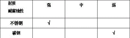
According to the table shown above; the utility model discloses axis of rotation 45 adopts the stainless steel, and corrosion resistance is strong, and is with low costs, the sexual valence relative altitude effect.
The patent states: the rotating shaft 45 is a rotating shaft, which is a common motion, when an object rotates, each point of the object makes circular motion, centers of the circles are on the same straight line, the straight line is called as a rotating shaft, and a door, a window, a grinding wheel, a rotor of a motor and the like are provided with fixed rotating shafts, so that only rotation can be performed, but translation cannot be performed.
The working principle is as follows: firstly, the novel power grid safety telescopic fence is placed at a proper position, then relative pulling force is applied to the supporting rods 1 at the left end and the right end, the telescopic fence 5 is opened for protection, the bottom end face of the connecting seat 3 is provided with the fixed supporting device 4, then pulling force is applied to the insertion cone 46, the insertion cone 46 is rotated to a vertical position from the groove 44 through the rotating shaft 45, the inner diameter size of the groove 44 is larger than the outer diameter size 5MM of the insertion cone 46, the insertion cone 46 is ensured to normally rotate in the groove 44 and is inserted into the ground for fixing, the shaking of the telescopic fence caused by strong weather is avoided, the top end face of the supporting rod 1 is provided with the tenon-and-mortise quick connecting structure 2, then force is applied to the connecting piece 26, the clamping block on the fixing piece 25 is driven by the connecting piece 26 to be in clamping fit with the clamping groove 23 on the connecting, both ends all are provided with fixture block 24 and mounting 25 about connecting piece 26, and carry out the integral type with mounting 25 and be connected, be favorable to carrying out the bidirectional fixation, fixture block 24 on the mounting 25 of the connecting piece other end is connected with external guardrail, the rail shape that needs to put according to the electric wire netting carries out the high-speed joint and puts, realize the swing joint between rail and the rail, solved the inconvenient quick fixed connection of multi-angle that carries on between the prior art rail, work efficiency is low, inconvenient and ground insert fixedly, rock easily, poor stability's problem.
The basic principles and the main features of the invention and the advantages of the invention have been shown and described above, it will be evident to those skilled in the art that the invention is not limited to the details of the foregoing illustrative embodiments, but that the invention may be embodied in other specific forms without departing from the spirit or essential characteristics of the invention. The present embodiments are therefore to be considered in all respects as illustrative and not restrictive, the scope of the invention being indicated by the appended claims rather than by the foregoing description, and all changes which come within the meaning and range of equivalency of the claims are therefore intended to be embraced therein. Any reference sign in a claim should not be construed as limiting the claim concerned.
Furthermore, it should be understood that although the present description refers to embodiments, not every embodiment may contain only a single embodiment, and such description is for clarity only, and those skilled in the art should integrate the description, and the embodiments may be combined as appropriate to form other embodiments understood by those skilled in the art.
Claims (9)
1. A novel power grid safety telescopic fence comprises a supporting rod (1), a connecting seat (3) and a telescopic fence (5), wherein a mortise-tenon quick connecting structure (2) is arranged on the top end face of the supporting rod (1), the bottom end face of the supporting rod (1) is welded with the connecting seat (3) in a manual arc welding mode, a fixed supporting device (4) is arranged on the bottom end face of the connecting seat (3), and the inner side of the supporting rod (1) is in folding fit with the telescopic fence (5);
the method is characterized in that: still include mortise and tenon quick connect structure (2) and fixed support device (4), mortise and tenon quick connect structure (2) comprise support column (21), connecting block (22), draw-in groove (23), fixture block (24), mounting (25) and connecting piece (26), support column (21) all around the middle part with have fixed support effect connecting block (22) integral type be connected, draw-in groove (23) are embedded in middle part in connecting block (22) preceding terminal surface, draw-in groove (23) internal diameter surface and fixture block (24) external diameter surface screens cooperation, fixture block (24) preceding terminal surface is I-shaped connecting piece (26) integral type with preceding terminal surface and is connected, support column (21) bottom face realizes locking through bolt and bracing piece (1), fixed support device (4) are by base (41), non-slip mat (42), fixed plate (43), recess (44), Axis of rotation (45) and insert awl (46) and constitute, base (41) bottom face bonds the cooperation through powerful glue and slipmat (42), both ends are passed through the bolt and are realized locking with fixed plate (43) about base (41) bottom face, recess (44) embedding middle part in fixed plate (43) bottom face, recess (44) internal diameter surface outside is through axis of rotation (45) and insert awl (46) normal running fit, base (41) top middle part is passed through the bolt and is fixed with connecting seat (3) locking.
2. The novel power grid safety telescopic fence as claimed in claim 1, wherein: the connecting blocks (22) are provided with four blocks which are distributed in pairs in an opposite way.
3. The novel power grid safety telescopic fence as claimed in claim 1, wherein: the inner diameter of the clamping groove (23) is larger than the outer diameter of the clamping block (24) by 3 MM.
4. The novel power grid safety telescopic fence as claimed in claim 1, wherein: the left end and the right end of the connecting piece (26) are provided with a clamping block (24) and a fixing piece (25) and are integrally connected with the fixing piece (25).
5. The novel power grid safety telescopic fence as claimed in claim 1, wherein: the fixture block (24) is wide at the top and narrow at the bottom, and the top end surface is in a T shape.
6. The novel power grid safety telescopic fence as claimed in claim 1, wherein: the working temperature range of the support column (21) is minus 40 ℃ to 50 ℃, and the storage temperature range is minus 40 ℃ to 125 ℃.
7. The novel power grid safety telescopic fence as claimed in claim 1, wherein: two screw holes are formed in the middle of the top end face of the base (41), and the diameter of each screw hole is 8 MM.
8. The novel power grid safety telescopic fence as claimed in claim 1, wherein: the inner diameter of the groove (44) is larger than the outer diameter of the insertion cone (46) by 5 MM.
9. The novel power grid safety telescopic fence as claimed in claim 1, wherein: the insertion cones (46) are provided in two numbers, and are each inclined inward at an angle of 20 degrees.
Priority Applications (1)
| Application Number | Priority Date | Filing Date | Title |
|---|---|---|---|
| CN201921110682.6U CN210888306U (en) | 2019-07-16 | 2019-07-16 | Novel telescopic rail of electric wire netting safety |
Applications Claiming Priority (1)
| Application Number | Priority Date | Filing Date | Title |
|---|---|---|---|
| CN201921110682.6U CN210888306U (en) | 2019-07-16 | 2019-07-16 | Novel telescopic rail of electric wire netting safety |
Publications (1)
| Publication Number | Publication Date |
|---|---|
| CN210888306U true CN210888306U (en) | 2020-06-30 |
Family
ID=71311837
Family Applications (1)
| Application Number | Title | Priority Date | Filing Date |
|---|---|---|---|
| CN201921110682.6U Expired - Fee Related CN210888306U (en) | 2019-07-16 | 2019-07-16 | Novel telescopic rail of electric wire netting safety |
Country Status (1)
| Country | Link |
|---|---|
| CN (1) | CN210888306U (en) |
Cited By (1)
| Publication number | Priority date | Publication date | Assignee | Title |
|---|---|---|---|---|
| CN110439359A (en) * | 2019-07-16 | 2019-11-12 | 上海北堃电力科技有限公司 | A New Type of Power Grid Security Telescopic Fence |
-
2019
- 2019-07-16 CN CN201921110682.6U patent/CN210888306U/en not_active Expired - Fee Related
Cited By (1)
| Publication number | Priority date | Publication date | Assignee | Title |
|---|---|---|---|---|
| CN110439359A (en) * | 2019-07-16 | 2019-11-12 | 上海北堃电力科技有限公司 | A New Type of Power Grid Security Telescopic Fence |
Similar Documents
| Publication | Publication Date | Title |
|---|---|---|
| CN111800074B (en) | Photovoltaic structure for new energy building | |
| CN205725591U (en) | A kind of adjustable photovoltaic generating support | |
| CN110439359A (en) | A New Type of Power Grid Security Telescopic Fence | |
| CN208386461U (en) | A kind of novel photovoltaic power station ground pile | |
| CN211316026U (en) | A solar street light controller that is easy to disassemble and assemble | |
| CN214102565U (en) | Tree supporting device for garden construction | |
| CN221220689U (en) | Tower barrel and wind generating set | |
| CN203896259U (en) | Single-column photovoltaic support | |
| CN210343602U (en) | Base with good fixing effect for wind power generation | |
| CN210578373U (en) | Rotation type photovoltaic power generation board installing support | |
| CN217581519U (en) | Power transmission and transformation double-steel-pipe tower connecting node reinforcing structure | |
| CN218604287U (en) | Fruit tree is planted and is used trunk protector | |
| CN209799521U (en) | heavy ice area tower with wind-resistant structure | |
| CN220184824U (en) | Safety barrier for fan foundation construction | |
| CN213897141U (en) | Stiffness composite prefabricated sheet pile enclosure structure | |
| CN217010766U (en) | Mountain region photovoltaic device | |
| CN212012541U (en) | Photovoltaic power generation adjusts support | |
| CN223853970U (en) | A type of chain link fence | |
| CN221202422U (en) | Adjusting mechanism of solar panel | |
| CN221150759U (en) | Transmission line iron tower crossing frame convenient to dismantle | |
| CN216517098U (en) | Novel civil construction bearing structure | |
| CN214591279U (en) | Solar energy frame construction of multi-angle | |
| CN219197535U (en) | Stable support for wind power generation | |
| CN223806234U (en) | An easy-to-install vertical wind turbine | |
| CN223075276U (en) | Engineering management safety guard rail |
Legal Events
| Date | Code | Title | Description |
|---|---|---|---|
| GR01 | Patent grant | ||
| GR01 | Patent grant | ||
| CF01 | Termination of patent right due to non-payment of annual fee |
Granted publication date: 20200630 |
|
| CF01 | Termination of patent right due to non-payment of annual fee |