CN210866904U - Wisdom power consumption, safe power consumption control box - Google Patents
Wisdom power consumption, safe power consumption control box Download PDFInfo
- Publication number
- CN210866904U CN210866904U CN201922208773.XU CN201922208773U CN210866904U CN 210866904 U CN210866904 U CN 210866904U CN 201922208773 U CN201922208773 U CN 201922208773U CN 210866904 U CN210866904 U CN 210866904U
- Authority
- CN
- China
- Prior art keywords
- box
- box body
- heat dissipation
- strip
- cover plate
- Prior art date
- Legal status (The legal status is an assumption and is not a legal conclusion. Google has not performed a legal analysis and makes no representation as to the accuracy of the status listed.)
- Active
Links
Images


Landscapes
- Cooling Or The Like Of Electrical Apparatus (AREA)
Abstract
本实用新型属于控制箱技术领域,尤其为一种智慧用电、安全用电控制箱,包括箱体,所述箱体的内部为中空且正面开设有与箱体内部相连通进出口,所所述箱体的正面通过合页转动连接有箱门,所述箱体的顶部开设有与箱体内部相连通的散热缺口,所述箱体的顶部可拆卸固定有盖板。本实用新型盖板的内部通过散热缺口与连通缺口的配合与箱体的内部相连通,自然状态下,箱体的内部的热量会自下而上聚集在盖板的内部,然后热量可以通过盖板底部的条形散热孔排出到箱体外部,由于条形散热孔的出口朝向竖直往下,再配合防尘组件的设计,可以大部分的灰尘和杂质隔绝在外,在保证箱体体正常散热的同时还可以保证箱体内部的清洁。
The utility model belongs to the technical field of control boxes, in particular to a smart electricity and safe electricity control box, comprising a box body, the inside of the box body is hollow, and the front side is provided with an inlet and outlet that communicate with the inside of the box body. The front of the box body is rotatably connected with a box door through hinges, the top of the box body is provided with a heat dissipation gap that communicates with the inside of the box body, and a cover plate is detachably fixed on the top of the box body. The inside of the cover plate of the utility model is communicated with the inside of the box body through the cooperation of the heat dissipation gap and the communication gap. The strip-shaped heat dissipation holes at the bottom of the board are discharged to the outside of the box. Since the outlet of the strip-shaped heat dissipation holes faces vertically downward, and with the design of the dust-proof components, most of the dust and impurities can be isolated from the outside, ensuring the normal operation of the box body. It can also ensure the cleanliness of the inside of the box while dissipating heat.
Description
技术领域technical field
本实用新型涉及控制箱技术领域,具体为一种智慧用电、安全用电控制箱。The utility model relates to the technical field of control boxes, in particular to a control box for intelligent electricity consumption and safe electricity consumption.
背景技术Background technique
近年来,随着各种先进技术在电网中的广泛应用,智能化已经成为电网发展的必然趋势,发展智能电网已在世界范围内形成共识,但是现有技术中的智慧用电管理系统中的控制箱在使用的过程中,为了保证正常的散热,需要在柜体表面开设散热口,通过散热口将箱体内部的热量散失到空气中,对控制箱内部的电器元件提供一个合适的工作环境,但是散热孔位置的设计容易造成外界灰尘和杂物进入到箱体的内部,灰尘和杂物粘附在电器元件上,会对电器元件的正常运行和工作带来影响,并且单一的散热孔无法满足控制箱的散热需求,因此目前的解决方案是通过增加散热风机来提高箱体内部的散热效果,但是目前散热风机等结构的设计会占据箱体的大量空间,使箱体内部空间容错率低,不便于对箱体内部的电器元件进行检修,因此,本实用新型提出一种智慧用电、安全用电控制箱。In recent years, with the wide application of various advanced technologies in the power grid, intelligence has become an inevitable trend in the development of power grids. The development of smart grids has reached a consensus around the world. During the use of the control box, in order to ensure normal heat dissipation, it is necessary to open a heat dissipation port on the surface of the cabinet body, and through the heat dissipation port, the heat inside the box body is dissipated into the air, so as to provide a suitable working environment for the electrical components inside the control box. , but the design of the heat dissipation hole position is easy to cause external dust and debris to enter the inside of the box, and the dust and debris adhere to the electrical components, which will affect the normal operation and work of the electrical components, and a single heat dissipation hole It cannot meet the cooling requirements of the control box, so the current solution is to increase the cooling effect inside the box by adding a cooling fan. However, the current design of the cooling fan and other structures will occupy a lot of space in the box, making the internal space of the box fault-tolerant. It is inconvenient to overhaul the electrical components inside the box body, therefore, the utility model proposes a control box for intelligent electricity consumption and safe electricity consumption.
实用新型内容Utility model content
(一)解决的技术问题(1) Technical problems solved
针对现有技术的不足,本实用新型提供了一种智慧用电、安全用电控制箱,解决了现有用电控制箱散热孔位置结构不合理,散热结构占据箱体内部空间的问题。Aiming at the deficiencies of the prior art, the utility model provides a control box for intelligent electricity consumption and safe electricity consumption, which solves the problems of unreasonable position and structure of the heat dissipation holes of the existing electricity consumption control box, and the heat dissipation structure occupies the inner space of the box body.
(二)技术方案(2) Technical solutions
为实现上述目的,本实用新型提供如下技术方案:一种智慧用电、安全用电控制箱,包括箱体,所述箱体的内部为中空且正面开设有与箱体内部相连通进出口,所所述箱体的正面通过合页转动连接有箱门,所述箱体的顶部开设有与箱体内部相连通的散热缺口,所述箱体的顶部可拆卸固定有盖板,所述盖板的内部为中空且底部开设有与盖板的内部相连通的连通缺口,所述箱体的内部通过散热缺口和连通缺口的配合与盖板的内部相连通,所述盖板的底部开设有不少于三个与其内部相连通的条形散热孔,所述盖板的底部可拆卸固定有用于对条形散热孔防尘的防尘组件,所述箱体内壁的底部放置有通风框,所述通风框的内部为中空且其顶部开设有不少于七个与其内部相连通的条形吹风孔,所述箱体的一侧设置有用于往通风框内部输送风的输风组件。In order to achieve the above purpose, the present utility model provides the following technical solutions: a control box for smart electricity and safe electricity use, comprising a box body, the interior of the box body is hollow, and the front side is provided with an inlet and outlet that communicate with the inside of the box body, The front of the box body is rotatably connected with a box door through hinges, the top of the box body is provided with a heat dissipation gap that communicates with the inside of the box body, a cover plate is detachably fixed on the top of the box body, and the cover The inside of the plate is hollow and the bottom is provided with a communication gap that communicates with the inside of the cover plate. The inside of the box is communicated with the inside of the cover plate through the cooperation of the heat dissipation gap and the communication gap. There are no less than three strip-shaped heat-dissipating holes communicated with the inside thereof, the bottom of the cover plate is detachably fixed with a dust-proof component for dust-proofing the strip-shaped heat-dissipating holes, and a ventilation frame is placed at the bottom of the inner wall of the box, The interior of the ventilation frame is hollow and the top of the ventilation frame is provided with no less than seven strip-shaped blowing holes communicating with the interior thereof. One side of the box body is provided with an air conveying assembly for conveying air to the interior of the ventilation frame.
作为本实用新型的一种优选技术方案,所述箱体内壁的顶部且对应散热缺口的位置处对称固定有两个安装块,两个所述安装块相对的一侧均开设有螺纹槽,所述盖板的底部且对应连通缺口的位置处固定安装矩形框条,所述矩形框条的一端贯穿散热缺口并延伸至箱体的内部,所述矩形框条四周的外表面与散热缺口四周的内壁均相互贴合,所述矩形框条的两侧均开设有贯穿矩形框条的通孔,所述矩形框条的两侧均通过螺栓与相对应的安装块固定连接。As a preferred technical solution of the present invention, two mounting blocks are symmetrically fixed on the top of the inner wall of the box and at the position corresponding to the heat dissipation gap, and the opposite sides of the two mounting blocks are provided with threaded grooves, so A rectangular frame strip is fixedly installed at the bottom of the cover plate and at the position corresponding to the communication gap. The inner walls are attached to each other, the two sides of the rectangular frame strip are provided with through holes penetrating the rectangular frame strip, and the two sides of the rectangular frame strip are fixedly connected with the corresponding mounting blocks by bolts.
作为本实用新型的一种优选技术方案,所述防尘组件的数量与条形散热孔的数量相等。As a preferred technical solution of the present invention, the number of the dust-proof components is equal to the number of the strip-shaped heat dissipation holes.
作为本实用新型的一种优选技术方案,所述防尘组件包括两个定位螺柱,两个所述定位螺柱对称固定盖板的底部且位于相对应条形散热孔的两侧,两个所述定位螺柱上活动套接有防尘框,两个所述定位螺柱上均螺纹连接有螺纹环。As a preferred technical solution of the present invention, the dustproof assembly includes two positioning studs, and the two positioning studs are symmetrically fixed to the bottom of the cover plate and are located on both sides of the corresponding strip-shaped heat dissipation holes. A dustproof frame is movably sleeved on the positioning studs, and a threaded ring is threadedly connected to the two positioning studs.
作为本实用新型的一种优选技术方案,所述定位螺柱上开设有内螺纹,所述螺纹环的内壁开设有外螺纹,所述防尘框上开设有两个与定位螺柱直径相等的穿孔。As a preferred technical solution of the present invention, the positioning stud is provided with an internal thread, the inner wall of the threaded ring is provided with an external thread, and the dust-proof frame is provided with two diameters equal to the positioning stud. perforation.
作为本实用新型的一种优选技术方案,所述输风组件包括防护箱,所述防护箱固定在箱体的一侧,所述防护箱内壁的底部固定安装有鼓风机,所述防护箱的背面开设有通气孔并设置有将通气孔遮挡的滤网框,所述鼓风机的出风口连通输风管,所述输风管的一端依次贯穿防护箱和箱体并与通风框的内部相连通。As a preferred technical solution of the present invention, the air transmission assembly includes a protective box, the protective box is fixed on one side of the box body, the bottom of the inner wall of the protective box is fixedly installed with a blower, and the back of the protective box is fixedly installed with a blower. A ventilation hole is opened and a screen frame is arranged to cover the ventilation hole. The air outlet of the blower is connected with an air supply pipe, and one end of the air supply pipe passes through the protective box and the box body in turn and communicates with the interior of the ventilation frame.
作为本实用新型的一种优选技术方案,所述通风框的一侧开设有进出孔,所述输风管一端贯穿进出孔并延伸至通风框的内部,所述进出孔的直径大于输风管的外径,所述进出孔的内部卡接有橡胶密封圈。As a preferred technical solution of the present invention, one side of the ventilation frame is provided with an inlet and outlet hole, one end of the air supply pipe penetrates the inlet and outlet hole and extends to the interior of the ventilation frame, and the diameter of the inlet and outlet holes is larger than that of the air supply pipe The outer diameter of the inlet and outlet holes is clamped with a rubber sealing ring.
(三)有益效果(3) Beneficial effects
与现有技术相比,本实用新型提供了一种智慧用电、安全用电控制箱,具备以下有益效果:Compared with the prior art, the utility model provides a control box for intelligent electricity consumption and safe electricity consumption, which has the following beneficial effects:
1、该智慧用电、安全用电控制箱,盖板的内部通过散热缺口与连通缺口的配合与箱体的内部相连通,自然状态下,箱体的内部的热量会自下而上聚集在盖板的内部,然后热量可以通过盖板底部的条形散热孔排出到箱体外部,由于条形散热孔的出口朝向竖直往下,再配合防尘组件的设计,可以大部分的灰尘和杂质隔绝在外,在保证箱体体正常散热的同时还可以保证箱体内部的清洁,同时设计在箱体外侧的输风组件往通风框的内部输送风,由于条形吹风孔开设在通风框的顶部,因此散热风自下而上流通,可以将热量快速带出箱体并通过盖板上的条形散热孔排出,同时输风组件位置的设计,提高了箱体内部空间的容错率,方便对箱体内部的电器元件进行检查和检修。1. In this smart electricity and safe electricity control box, the inside of the cover is connected to the inside of the box through the cooperation of the heat dissipation gap and the communication gap. In a natural state, the heat inside the box will accumulate in the The inside of the cover plate, and then the heat can be discharged to the outside of the box through the strip-shaped heat dissipation holes at the bottom of the cover plate. Since the outlet of the strip-shaped heat dissipation holes faces vertically downward, combined with the design of the dust-proof components, most of the dust and heat can be removed. The impurities are isolated from the outside, which not only ensures the normal heat dissipation of the box body, but also ensures the cleanliness of the inside of the box body. At the same time, the air delivery component designed on the outside of the box body delivers air to the interior of the ventilation frame. The top, so the heat dissipation air flows from bottom to top, which can quickly take the heat out of the box and discharge it through the strip-shaped heat dissipation holes on the cover plate. At the same time, the design of the position of the air supply component improves the fault tolerance rate of the internal space of the box, which is convenient and convenient. Check and overhaul the electrical components inside the box.
2、该智慧用电、安全用电控制箱,其中盖板与箱体直接通过安装块和矩形框条的配合完成固定,由于矩形框条位于箱体的内部,并且固定位置位于箱体的内部,保证了盖板与箱体之间的密封性,在户外使用时,可以保证盖板与箱体之间连接位置的防水性。2. In this smart electricity and safe electricity control box, the cover plate and the box body are directly fixed by the cooperation of the installation block and the rectangular frame strip. Since the rectangular frame strip is located inside the box body, and the fixing position is located inside the box body , to ensure the sealing between the cover plate and the box body, and to ensure the waterproofness of the connection position between the cover plate and the box body when used outdoors.
3、该智慧用电、安全用电控制箱,防尘框通过定位螺柱和螺纹环的配合固定在盖板的底部,通过防尘框可以对条形散热孔进行遮挡起到防尘作用,提高了本实用新型的防尘性,同时方便将防尘框进行拆卸更换和清理,结构设计简单并有效。3. In the smart electricity and safe electricity control box, the dust-proof frame is fixed on the bottom of the cover plate through the cooperation of positioning studs and threaded rings, and the strip-shaped heat dissipation holes can be shielded by the dust-proof frame to play a dust-proof effect. The dustproof performance of the utility model is improved, and at the same time, the dustproof frame is convenient for disassembly, replacement and cleaning, and the structure design is simple and effective.
附图说明Description of drawings
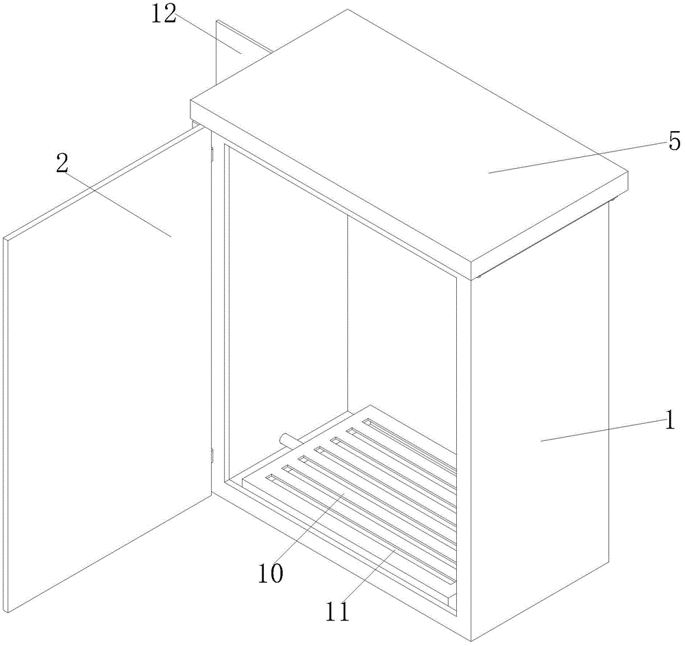
图1为本实用新型立体结构正视图;1 is a front view of a three-dimensional structure of the present utility model;
图2为本实用新型立体结构仰视图;Fig. 2 is the bottom view of the three-dimensional structure of the present utility model;
图3为本实用新型立体结构后视图;Fig. 3 is the rear view of the three-dimensional structure of the utility model;
图4为本实用新型箱体结构立体图;4 is a perspective view of the box structure of the present utility model;
图5为本实用新型盖板结构立体图;5 is a perspective view of a cover plate structure of the present invention;
图6为本实用新型通风框结构立体图。FIG. 6 is a perspective view of the structure of the ventilation frame of the present invention.
图中:1、箱体;2、箱门;3、散热缺口;4、安装块;5、盖板;6、连通缺口;7、矩形框条;8、条形散热孔;9、防尘组件;901、定位螺柱;902、防尘框;903、螺纹环;10、通风框;11、条形吹风孔;12、输风组件;121、防护箱;122、鼓风机;123、滤网框;124、输风管;13、进出孔;14、橡胶密封圈。In the picture: 1. Box body; 2. Box door; 3. Heat dissipation gap; 4. Mounting block; 5. Cover plate; 6. Connecting gap; 7. Rectangular frame strip; 8. Strip cooling hole; 9. Dustproof Component; 901, positioning stud; 902, dustproof frame; 903, threaded ring; 10, ventilation frame; 11, strip air hole; 12, air supply assembly; 121, protective box; 122, blower; 123, filter screen frame; 124, air supply pipe; 13, inlet and outlet holes; 14, rubber sealing ring.
具体实施方式Detailed ways
下面将结合本实用新型实施例中的附图,对本实用新型实施例中的技术方案进行清楚、完整地描述,显然,所描述的实施例仅仅是本实用新型一部分实施例,而不是全部的实施例。基于本实用新型中的实施例,本领域普通技术人员在没有做出创造性劳动前提下所获得的所有其他实施例,都属于本实用新型保护的范围。The technical solutions in the embodiments of the present utility model will be clearly and completely described below with reference to the accompanying drawings in the embodiments of the present utility model. Obviously, the described embodiments are only a part of the embodiments of the present utility model, rather than all the implementations. example. Based on the embodiments of the present invention, all other embodiments obtained by those of ordinary skill in the art without creative work fall within the protection scope of the present invention.
实施例Example
请参阅图1-6,本实用新型提供以下技术方案:一种智慧用电、安全用电控制箱,包括箱体1,箱体1的内部为中空且正面开设有与箱体1内部相连通进出口,所箱体1的正面通过合页转动连接有箱门2,箱体1的顶部开设有与箱体1内部相连通的散热缺口3,箱体1的顶部可拆卸固定有盖板5,盖板5的内部为中空且底部开设有与盖板5的内部相连通的连通缺口6,箱体1的内部通过散热缺口3和连通缺口6的配合与盖板5的内部相连通,盖板5的底部开设有不少于三个与其内部相连通的条形散热孔8,盖板5的底部可拆卸固定有用于对条形散热孔8防尘的防尘组件9,箱体1内壁的底部放置有通风框10,通风框10的内部为中空且其顶部开设有不少于七个与其内部相连通的条形吹风孔11,箱体1的一侧设置有用于往通风框10内部输送风的输风组件12。Please refer to FIGS. 1-6 , the present invention provides the following technical solutions: a smart electricity and safe electricity control box, including a
本实施方案中,正常情况下将箱门2关闭,把箱体1正面的进出口给遮挡住,保存箱体1内部处于一个封闭环境;盖板5的内部通过散热缺口3与连通缺口6的配合与箱体1的内部相连通,自然状态下,箱体1的内部的热量会自下而上聚集在盖板5的内部,然后热量可以通过盖板5底部的条形散热孔8排出到箱体1外部,由于条形散热孔8的出口朝向竖直往下,再配合防尘组件9的设计,可以大部分的灰尘和杂质隔绝在外,在保证箱体1正常散热的同时还可以保证箱体1内部的清洁,同时设计在箱体1外侧的输风组件12往通风框10的内部输送风,由于条形吹风孔11开设在通风框10的顶部,因此散热风自下而上流通,可以将热量快速带出箱体1并通过盖板5上的条形散热孔8排出,同时输风组件12位置的设计,提高了箱体1内部空间的容错率,方便对箱体1内部的电器元件进行检查和检修。In this embodiment, under normal circumstances, the
具体的,箱体1内壁的顶部且对应散热缺口3的位置处对称固定有两个安装块4,两个安装块4相对的一侧均开设有螺纹槽,盖板5的底部且对应连通缺口6的位置处固定安装矩形框条7,矩形框条7的一端贯穿散热缺口3并延伸至箱体1的内部,矩形框条7四周的外表面与散热缺口3四周的内壁均相互贴合,矩形框条7的两侧均开设有贯穿矩形框条7的通孔,矩形框条7的两侧均通过螺栓与相对应的安装块4固定连接。Specifically, two mounting blocks 4 are symmetrically fixed on the top of the inner wall of the
本实施例中,盖板5与箱体1直接通过安装块4和矩形框条7的配合完成固定,由于矩形框条7位于箱体1的内部,并且固定位置位于箱体1的内部,直接利用螺栓穿过矩形框条7上的通孔与安装块4上的螺纹槽进行螺栓连接即可,固定后的矩形框条7的四周的外表面与散热缺口3四周的内壁均相互贴合,保证了盖板5与箱体1之间的密封性,在户外使用时,还可以保证盖板5与箱体1之间连接位置的防水性。In this embodiment, the
具体的,防尘组件9的数量与条形散热孔8的数量相等。Specifically, the number of the
本实施例中,确保了每个条形散热孔8都有对应的防尘组件9对其进行防尘处理。In this embodiment, it is ensured that each strip-shaped
具体的,防尘组件9包括两个定位螺柱901,两个定位螺柱901对称固定盖板5的底部且位于相对应条形散热孔8的两侧,两个定位螺柱901上活动套接有防尘框902,两个定位螺柱901上均螺纹连接有螺纹环903。Specifically, the
本实施例中,防尘框902通过定位螺柱901和螺纹环903的配合固定在盖板5的底部,通过防尘框902可以对条形散热孔8进行遮挡起到防尘作用,提高了本实用新型的防尘性,同时方便将防尘框902进行拆卸更换和清理,结构设计简单并有效,其中螺纹环903与定位螺柱901螺纹连接后,将螺纹环903的一端抵触在防尘框902的底部,使防尘框902与盖板5的底部紧密贴合。In this embodiment, the
具体的,定位螺柱901上开设有内螺纹,螺纹环903的内壁开设有外螺纹,防尘框902上开设有两个与定位螺柱901直径相等的穿孔。Specifically, the
本实施例中,保证防尘框902可以顺利放置在定位螺柱901上。In this embodiment, it is ensured that the
具体的,输风组件12包括防护箱121,防护箱121固定在箱体1的一侧,防护箱121内壁的底部固定安装有鼓风机122,防护箱121的背面开设有通气孔并设置有将通气孔遮挡的滤网框123,鼓风机122的出风口连通输风管124,输风管124的一端依次贯穿防护箱121和箱体1并与通风框10的内部相连通。Specifically, the
本实施例中,鼓风机122工作将风通过输风管124输送进通风框10的内部,然后风通过通风框10上的条形吹风孔11自下而上流通即可,其中防护箱121为一个完整体,并且防护箱121与外界空气连通的位置处安装有滤网框123,并且滤网框123可以拆卸进行清理,因此保证进入到箱体1内部的空气中只有少量的灰尘和杂质。In this embodiment, the
具体的,通风框10的一侧开设有进出孔13,输风管124一端贯穿进出孔13并延伸至通风框10的内部,进出孔13的直径大于输风管124的外径,进出孔13的内部卡接有橡胶密封圈14。Specifically, one side of the
本实施例中,往箱体1内部的输送的空气中会有少量的灰尘和杂质,这些杂质会积累在通风框10的内部,由于通风框10放置在箱体1的内部,并且通风框10与输风管124为活动连接,因此方便将通风框10取出进行清理,其中橡胶密封圈14位于通风框10外部部分的外径大于进出孔13的内径,将橡胶密封圈14塞入进进出孔13的内部将其固定即可。In this embodiment, there will be a small amount of dust and impurities in the air transported to the inside of the
最后应说明的是:以上所述仅为本实用新型的优选实施例而已,并不用于限制本实用新型,尽管参照前述实施例对本实用新型进行了详细的说明,对于本领域的技术人员来说,其依然可以对前述各实施例所记载的技术方案进行修改,或者对其中部分技术特征进行等同替换。凡在本实用新型的精神和原则之内,所作的任何修改、等同替换、改进等,均应包含在本实用新型的保护范围之内。Finally, it should be noted that the above are only the preferred embodiments of the present invention, and are not intended to limit the present invention. , it is still possible to modify the technical solutions described in the foregoing embodiments, or perform equivalent replacements to some of the technical features. Any modification, equivalent replacement, improvement, etc. made within the spirit and principle of the present invention shall be included in the protection scope of the present invention.
Claims (7)
Priority Applications (1)
| Application Number | Priority Date | Filing Date | Title |
|---|---|---|---|
| CN201922208773.XU CN210866904U (en) | 2019-12-11 | 2019-12-11 | Wisdom power consumption, safe power consumption control box |
Applications Claiming Priority (1)
| Application Number | Priority Date | Filing Date | Title |
|---|---|---|---|
| CN201922208773.XU CN210866904U (en) | 2019-12-11 | 2019-12-11 | Wisdom power consumption, safe power consumption control box |
Publications (1)
| Publication Number | Publication Date |
|---|---|
| CN210866904U true CN210866904U (en) | 2020-06-26 |
Family
ID=71285501
Family Applications (1)
| Application Number | Title | Priority Date | Filing Date |
|---|---|---|---|
| CN201922208773.XU Active CN210866904U (en) | 2019-12-11 | 2019-12-11 | Wisdom power consumption, safe power consumption control box |
Country Status (1)
| Country | Link |
|---|---|
| CN (1) | CN210866904U (en) |
Cited By (1)
| Publication number | Priority date | Publication date | Assignee | Title |
|---|---|---|---|---|
| CN112333952A (en) * | 2020-11-11 | 2021-02-05 | 中国电子科技集团公司第十四研究所 | Carbon fiber air-cooled case for airborne information processing |
-
2019
- 2019-12-11 CN CN201922208773.XU patent/CN210866904U/en active Active
Cited By (1)
| Publication number | Priority date | Publication date | Assignee | Title |
|---|---|---|---|---|
| CN112333952A (en) * | 2020-11-11 | 2021-02-05 | 中国电子科技集团公司第十四研究所 | Carbon fiber air-cooled case for airborne information processing |
Similar Documents
| Publication | Publication Date | Title |
|---|---|---|
| CN205160559U (en) | An intelligent automatic dust-proof and heat-dissipating switchboard | |
| CN206461234U (en) | A kind of power engineering switch board | |
| CN104426811A (en) | Heat radiation dustproof switch device | |
| CN205546361U (en) | A cooling device for power communication | |
| CN209882331U (en) | Dustproof install bin of heat dissipation of electric automation control device | |
| CN113534915A (en) | Industrial control computer of intelligence | |
| CN207664447U (en) | A kind of flour processing power distribution cabinet of good dustproof effect | |
| CN208955913U (en) | A kind of power supply adaptor | |
| CN207834993U (en) | A kind of multiplex roles computer network terminal box | |
| CN212392566U (en) | Assembled block terminal | |
| CN217037751U (en) | Wireless energy management monitoring device | |
| CN205302131U (en) | Can play computer box of dustproof effect | |
| CN216699136U (en) | Anti-corrosion switchgear in coastal areas | |
| CN211406668U (en) | Improved network server case | |
| CN210926820U (en) | A high and low voltage switch cabinet capable of rainwater heat exchange | |
| CN210379813U (en) | Laboratory is with dustless switch board of intelligence | |
| CN203086876U (en) | Dust-free cabinet | |
| CN209131088U (en) | An energy-saving fresh air purification unit | |
| CN220874045U (en) | Energy-saving fan variable frequency control cabinet | |
| CN221710281U (en) | Sewage treatment control cabinet convenient to heat dissipation is dustproof | |
| CN210926701U (en) | High-voltage electrical cabinet suitable for it is outdoor | |
| CN220421166U (en) | Environment-friendly and energy-saving low-voltage switch cabinet | |
| CN216850890U (en) | Electric power cabinet with dustproof heat dissipation function | |
| CN220358660U (en) | Control cabinet heat abstractor | |
| CN204961348U (en) | Prevent dust and destatic quick -witted case fan |
Legal Events
| Date | Code | Title | Description |
|---|---|---|---|
| GR01 | Patent grant | ||
| GR01 | Patent grant | ||
| TR01 | Transfer of patent right | ||
| TR01 | Transfer of patent right |
Effective date of registration: 20260123 Address after: 214000 Jiangsu Province Wuxi City Liangxi District Wuhe Community Antou Bridge 20 Hao Patentee after: Wuxi Shuntong Electric Appliance Installation Co.,Ltd. Country or region after: China Address before: 214000 Jiangsu Province Wuxi City Liyuan Development Zone Dicui Road 100 Creative Park Building 10 508 Patentee before: Jiangsu zhongzhitian Intelligent Technology Co.,Ltd. Country or region before: China |