CN210860280U - Exhaust pipeline with dust removal function for clean workshop - Google Patents
Exhaust pipeline with dust removal function for clean workshop Download PDFInfo
- Publication number
- CN210860280U CN210860280U CN201921856977.8U CN201921856977U CN210860280U CN 210860280 U CN210860280 U CN 210860280U CN 201921856977 U CN201921856977 U CN 201921856977U CN 210860280 U CN210860280 U CN 210860280U
- Authority
- CN
- China
- Prior art keywords
- exhaust duct
- dust
- movable rod
- wall
- brush
- Prior art date
- Legal status (The legal status is an assumption and is not a legal conclusion. Google has not performed a legal analysis and makes no representation as to the accuracy of the status listed.)
- Active
Links
- 239000000428 dust Substances 0.000 title claims abstract description 63
- 238000007789 sealing Methods 0.000 claims 2
- 238000010408 sweeping Methods 0.000 abstract description 2
- 238000010586 diagram Methods 0.000 description 7
- 238000009434 installation Methods 0.000 description 4
- 238000004140 cleaning Methods 0.000 description 3
- 230000003749 cleanliness Effects 0.000 description 2
- 238000000034 method Methods 0.000 description 2
- 238000012986 modification Methods 0.000 description 2
- 230000004048 modification Effects 0.000 description 2
- 241000894006 Bacteria Species 0.000 description 1
- 230000009286 beneficial effect Effects 0.000 description 1
- 238000006243 chemical reaction Methods 0.000 description 1
- 230000005611 electricity Effects 0.000 description 1
- 239000003344 environmental pollutant Substances 0.000 description 1
- 238000000605 extraction Methods 0.000 description 1
- 231100000719 pollutant Toxicity 0.000 description 1
- 230000003068 static effect Effects 0.000 description 1
Images


Landscapes
- Filtering Of Dispersed Particles In Gases (AREA)
Abstract
本实用新型公开了一种具有除尘功能的洁净车间用排风管道,属于排风管道技术领域,包括排风管道本体,所述排风管道本体的内部设置有固定板,所述固定板的内部设置有灰尘过滤网,所述灰尘过滤网的边侧设置有毛刷,所述毛刷固定于活动杆的边侧,所述活动杆的中部连接有第一转轴,所述第一转轴的端部贯穿于承重板的内部与第一锥形齿轮相互连接,所述承重板的端部安装于排风管道本体的内壁,所述套杆的上端嵌套有弹簧,所述弹簧位于套筒的内部;本实用新型扫灰机构包括活动杆和毛刷等零件,且通过旋转把手,能够使得活动杆和毛刷旋转,从而能够将吸附在灰尘过滤网上的灰尘扫落下来,进而避免了拆卸灰尘过滤网进行灰尘清理,提升了工作效率。
The utility model discloses an exhaust duct for a clean workshop with dust removal function, belonging to the technical field of exhaust ducts. The utility model comprises an exhaust duct body. A fixing plate is arranged inside the exhaust duct body. A dust filter is provided, and a brush is arranged on the side of the dust filter. The brush is fixed on the side of the movable rod. The middle of the movable rod is connected with a first rotating shaft, and the end of the first rotating shaft is connected. The end of the load-bearing plate is installed on the inner wall of the exhaust duct body, the upper end of the sleeve rod is nested with a spring, and the spring is located at the end of the sleeve. Inside; the dust-sweeping mechanism of the utility model includes parts such as a movable rod and a brush, and by rotating the handle, the movable rod and the brush can be rotated, so that the dust adsorbed on the dust filter net can be swept down, thereby avoiding the disassembly of the dust The filter screen cleans dust and improves work efficiency.
Description
技术领域technical field
本实用新型属于洁净车间排风管道技术领域,且IPC分类号为B01D50/00,具体涉及一种具有除尘功能的洁净车间用排风管道。The utility model belongs to the technical field of an exhaust duct for a clean workshop, and the IPC classification number is B01D50/00, in particular to an exhaust duct for a clean workshop with a dust removal function.
背景技术Background technique
洁净车间也叫无尘车间和洁净室,是指将一定空间范围之内空气中的微粒子、有害空气、细菌等污染物排除,并将室内温度、洁净度、室内压力、气流速度与气流分布、噪音振动及照明、静电控制在某一需求范围内,而所给予特别设计的房间,且洁净车间在排气时,需要使用到排风管道,从而能够将洁净车间内部含有灰尘的空气排出,使得洁净车间内部能够保持良好的洁净度。A clean workshop is also called a dust-free workshop and a clean room, which refers to the removal of particulates, harmful air, bacteria and other pollutants in the air within a certain space, and the indoor temperature, cleanliness, indoor pressure, airflow speed and airflow distribution. Noise, vibration, lighting, and static electricity are controlled within a certain range of requirements, and the specially designed room is given, and the clean room needs to use an exhaust duct when exhausting, so that the air containing dust in the clean room can be discharged, making The interior of the clean workshop can maintain good cleanliness.
如公开号为CN205127637U的实用新型所公开的滤尘室外排风管道,其虽然设置有除尘网,使得排风管道具有除尘的功能,但是除尘网长时间使用后,会导致除尘网上的网孔堵塞,因此需要拆卸下来进行清理,导致清理起来较为麻烦,而该排风管道需要将除尘网拆卸下来,才能够清理灰尘,从而导致操作麻烦,影响工作效率,为此我们提出一种具有除尘功能的洁净车间用排风管道。For example, the dust filter outdoor exhaust duct disclosed by the utility model with the publication number of CN205127637U, although it is provided with a dedusting net, so that the exhaust duct has the function of dedusting, but after the dedusting net is used for a long time, the mesh holes on the dedusting net will be blocked. Therefore, it needs to be disassembled for cleaning, which makes it more troublesome to clean up, and the exhaust duct needs to be disassembled to remove the dust net to be able to clean the dust, which leads to troublesome operation and affects work efficiency. Exhaust ducts for workshops.
实用新型内容Utility model content
本实用新型的目的在于提供一种具有除尘功能的洁净车间用排风管道,以解决上述背景技术中提出的问题。The purpose of the present invention is to provide an exhaust duct for a clean workshop with a dust removal function, so as to solve the problems raised in the above-mentioned background technology.
为实现上述目的,本实用新型提供如下技术方案:一种具有除尘功能的洁净车间用排风管道,包括排风管道本体,所述排风管道本体的内部设置有固定板,所述固定板的内部设置有灰尘过滤网,所述灰尘过滤网的边侧设置有毛刷,所述毛刷固定于活动杆的边侧,所述活动杆的中部连接有第一转轴,所述第一转轴的端部贯穿于承重板的内部与第一锥形齿轮相互连接,所述承重板的端部安装于排风管道本体的内壁,所述第一锥形齿轮通过第二锥形齿轮与第二转轴的下端相互连接,所述第二转轴的上端贯穿于排风管道本体的顶部与把手相互连接,所述排风管道本体的底部设置有集灰斗,所述集灰斗的底部安装有塞子,所述塞子的外壁铺设有橡胶密封件,所述塞子边侧的底部连接有横杆,所述横杆顶部的边侧固定有套杆,所述套杆的上端连接有限位块,所述限位块位于套筒的内部,所述套筒的上端固定于排风管道本体的底部,所述套杆的上端嵌套有弹簧,所述弹簧位于套筒的内部。In order to achieve the above purpose, the present utility model provides the following technical solutions: an exhaust duct for a clean workshop with a dust removal function, comprising an exhaust duct body, and a fixing plate is arranged inside the exhaust duct body, and the fixed plate is The inside is provided with a dust filter screen, the side of the dust filter screen is provided with a brush, the brush is fixed on the side of the movable rod, the middle of the movable rod is connected with a first rotating shaft, and the The end penetrates through the interior of the bearing plate and is connected to the first bevel gear, the end of the bearing plate is mounted on the inner wall of the exhaust duct body, and the first bevel gear is connected to the second rotating shaft through the second bevel gear The lower ends of the ducts are connected to each other, the upper end of the second shaft runs through the top of the exhaust duct body and is connected to the handle, the bottom of the exhaust duct body is provided with an ash collecting hopper, and the bottom of the ash collecting hopper is installed with a plug, The outer wall of the plug is covered with a rubber seal, the bottom of the side of the plug is connected with a crossbar, the side of the top of the crossbar is fixed with a sleeve rod, the upper end of the sleeve rod is connected with a limit block, the limit The position block is located inside the sleeve, the upper end of the sleeve is fixed on the bottom of the exhaust duct body, the upper end of the sleeve rod is nested with a spring, and the spring is located inside the sleeve.
优选的,所述灰尘过滤网设计为圆形结构,所述灰尘过滤网的中心轴线与活动杆的中心轴线相互重合,所述活动杆的长度大于灰尘过滤网的直径3cm。Preferably, the dust filter is designed in a circular structure, the central axis of the dust filter coincides with the central axis of the movable rod, and the length of the movable rod is 3 cm greater than the diameter of the dust filter.
优选的,所述毛刷在活动杆的边侧等间距分布,所述毛刷的端部与灰尘过滤网的边侧相互贴合。Preferably, the brushes are distributed at equal intervals on the sides of the movable rod, and the ends of the brushes are attached to the sides of the dust filter.
优选的,所述第一锥形齿轮和第二锥形齿轮相互垂直设计,所述第一锥形齿轮和第二锥形齿轮为啮合连接。Preferably, the first bevel gear and the second bevel gear are designed to be perpendicular to each other, and the first bevel gear and the second bevel gear are in meshing connection.
优选的,所述塞子顶部的竖切面设计为三角形结构,所述塞子的外壁与橡胶密封件的内壁为粘贴连接,所述橡胶密封件的外壁与集灰斗底部的内侧相互贴合。Preferably, the vertical section of the top of the plug is designed as a triangular structure, the outer wall of the plug and the inner wall of the rubber seal are bonded and connected, and the outer wall of the rubber seal and the inner side of the bottom of the ash collecting hopper are attached to each other.
优选的,所述套杆的外壁与弹簧的内壁相互贴合,所述套杆与限位块组合成“T”字型结构。Preferably, the outer wall of the sleeve rod and the inner wall of the spring are attached to each other, and the sleeve rod and the limiting block are combined into a "T"-shaped structure.
优选的,所述限位块设计为矩形体结构,所述限位块与套筒构成卡合式的滑动结构。Preferably, the limiting block is designed as a rectangular body structure, and the limiting block and the sleeve form a snap-fit sliding structure.
与现有技术相比,本实用新型的有益效果是:Compared with the prior art, the beneficial effects of the present utility model are:
1、扫灰机构包括活动杆和毛刷等零件,且通过旋转把手,能够使得活动杆和毛刷旋转,从而能够将吸附在灰尘过滤网上的灰尘扫落下来,进而避免了拆卸灰尘过滤网进行灰尘清理,提升了工作效率。1. The dust-sweeping mechanism includes parts such as movable rods and brushes, and by rotating the handle, the movable rods and brushes can be rotated, so that the dust adsorbed on the dust filter can be swept off, thereby avoiding the need to disassemble the dust filter. Dust cleaning, improve work efficiency.
2、灰尘取出机构包括套杆、限位块、套筒和弹簧等零件,且通过下拉套杆,能够使得集灰斗的底部开启,从而使得灰尘能够取出,且松开套杆,弹簧产生的零件能够使得集灰斗的底部自动关闭,从而方便灰尘的取出。2. The dust extraction mechanism includes parts such as sleeve rods, limit blocks, sleeves and springs, and by pulling down the sleeve rods, the bottom of the ash collecting hopper can be opened, so that the dust can be taken out, and the sleeve rods are loosened. The part can make the bottom of the ash collecting hopper close automatically, so as to facilitate the removal of dust.
附图说明Description of drawings
图1为本实用新型整体结构示意图;Fig. 1 is the overall structure schematic diagram of the present utility model;
图2为本实用新型图1中正视结构示意图;Fig. 2 is the front view structure schematic diagram in Fig. 1 of the utility model;
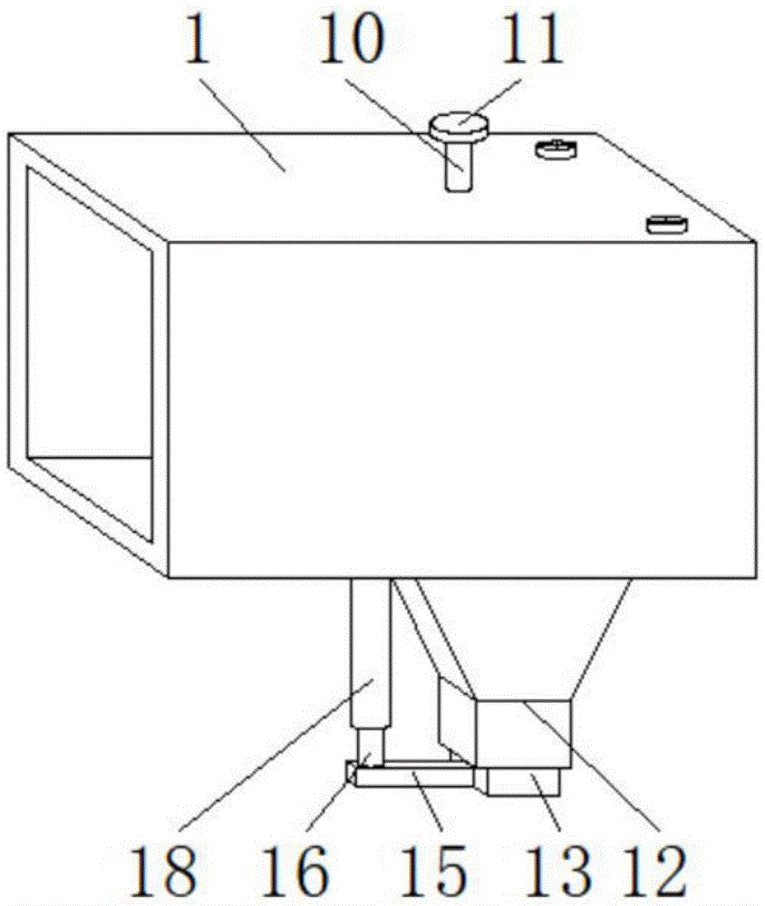
图3为本实用新型图1中套杆安装结构示意图;3 is a schematic diagram of the installation structure of the sleeve rod in FIG. 1 of the present utility model;
图4为本实用新型图2中A处放大结构示意图;Fig. 4 is the enlarged structural schematic diagram at A in Fig. 2 of the utility model;
图5为本实用新型图3中限位块安装结构示意图;FIG. 5 is a schematic diagram of the installation structure of the limit block in FIG. 3 of the present utility model;
图6为本实用新型图2中灰尘过滤网安装结构示意图;6 is a schematic diagram of the installation structure of the dust filter in FIG. 2 of the present utility model;
图7为本实用新型图4中塞子安装结构示意图;7 is a schematic diagram of the installation structure of the plug in FIG. 4 of the present utility model;
图中:1、排风管道本体;2、固定板;3、灰尘过滤网;4、毛刷;5、活动杆;6、第一转轴;7、承重板;8、第一锥形齿轮;9、第二锥形齿轮;10、第二转轴;11、把手;12、集灰斗;13、塞子;14、橡胶密封件;15、横杆;16、套杆;17、限位块;18、套筒;19、弹簧。In the figure: 1. Exhaust duct body; 2. Fixed plate; 3. Dust filter; 4. Brush; 5. Active rod; 6. First shaft; 7. Bearing plate; 8. First bevel gear; 9. The second bevel gear; 10. The second shaft; 11. The handle; 12. The ash hopper; 13. The plug; 14. The rubber seal; 15. The cross bar; 18. Sleeve; 19. Spring.
具体实施方式Detailed ways
下面将结合本实用新型实施例中的附图,对本实用新型实施例中的技术方案进行清楚、完整地描述,显然,所描述的实施例仅仅是本实用新型一部分实施例,而不是全部的实施例。基于本实用新型中的实施例,本领域普通技术人员在没有做出创造性劳动前提下所获得的所有其他实施例,都属于本实用新型保护的范围。The technical solutions in the embodiments of the present utility model will be clearly and completely described below with reference to the accompanying drawings in the embodiments of the present utility model. Obviously, the described embodiments are only a part of the embodiments of the present utility model, rather than all the implementations. example. Based on the embodiments of the present invention, all other embodiments obtained by those of ordinary skill in the art without creative work fall within the protection scope of the present invention.
请参阅图1、图2,图3和图4,本实用新型提供技术方案:一种具有除尘功能的洁净车间用排风管道,包括排风管道本体1,排风管道本体1的内部设置有固定板2,固定板2的内部设置有灰尘过滤网3,灰尘过滤网3的边侧设置有毛刷4,毛刷4固定于活动杆5的边侧,活动杆5的中部连接有第一转轴6,第一转轴6的端部贯穿于承重板7的内部与第一锥形齿轮8相互连接,承重板7的端部安装于排风管道本体1的内壁,第一锥形齿轮8通过第二锥形齿轮9与第二转轴10的下端相互连接,第二转轴10的上端贯穿于排风管道本体1的顶部与把手11相互连接,排风管道本体1的底部设置有集灰斗12,集灰斗12的底部安装有塞子13,塞子13的外壁铺设有橡胶密封件14,塞子13边侧的底部连接有横杆15,横杆15顶部的边侧固定有套杆16,套杆16的上端连接有限位块17,限位块17位于套筒18的内部,套筒18的上端固定于排风管道本体1的底部,套杆16的上端嵌套有弹簧19,弹簧19位于套筒18的内部。Please refer to Fig. 1, Fig. 2, Fig. 3 and Fig. 4, the present utility model provides a technical solution: an exhaust duct for a clean workshop with a dust removal function, comprising an
灰尘过滤网3设计为圆形结构,灰尘过滤网3的中心轴线与活动杆5的中心轴线相互重合,活动杆5的长度大于灰尘过滤网3的直径3cm,毛刷4在活动杆5的边侧等间距分布,毛刷4的端部与灰尘过滤网3的边侧相互贴合,为了便于灰尘过滤网3上吸附的灰尘扫落下来,如图2所示,在灰尘过滤网3的边侧设置有活动杆5,且活动杆5能够旋转,从而毛刷4能够将吸附在灰尘过滤网3上的灰尘扫落下来,避免了灰尘过滤网3拆卸清理,从而提升了工作效率。The
第一锥形齿轮8和第二锥形齿轮9相互垂直设计,第一锥形齿轮8和第二锥形齿轮9为啮合连接,为了便于水平方向的旋转转化成竖直方向的旋转,如图2所示,使得把手11能够安装在排风管道本体1的外部,从而方便通过把手11对活动杆5和毛刷4的旋转。The
塞子13顶部的竖切面设计为三角形结构,塞子13的外壁与橡胶密封件14的内壁为粘贴连接,橡胶密封件14的外壁与集灰斗12底部的内侧相互贴合,为了便于灰尘的取出,如图4所示,塞子13顶部的竖切面设计为三角形结构,从而使得落在塞子13顶部的灰尘能够自动落下来。The vertical section at the top of the
套杆16的外壁与弹簧19的内壁相互贴合,套杆16与限位块17组合成“T”字型结构,限位块17设计为矩形体结构,限位块17与套筒18构成卡合式的滑动结构,为了便于塞子13能够自动将集灰斗12的底部堵住,如图3所示,在套杆16的外侧嵌套有弹簧19,使得套杆16移动后,能够恢复到原位置,同时限位块17避免了套杆16的旋转,从而使得塞子13能够自动将集灰斗12的底部堵住。The outer wall of the
本实用新型的工作原理及使用流程:该装置在使用时,首先灰尘过滤网3上灰尘较多需要清理时,此时旋转把手11,接着把手11通过第二转轴10、第二锥形齿轮9、第一锥形齿轮8和第一转轴6带动活动杆5旋转,同时活动杆5带动毛刷4旋转,从而毛刷4能够将吸附在灰尘过滤网3上的灰尘扫落到集灰斗12的内部,然后向下拉动横杆15,接着横杆15带动塞子13和橡胶密封件14向下移动,使得集灰斗12内部的灰尘能够排出,同时横杆15带动套杆16和限位块17向下移动,使得弹簧19被压缩,由于限位块17为矩形体,从而保证了塞子13只能上下移动,进而保证了松开横杆15时,弹簧19被产生的弹力能够使得塞子13和橡胶密封件14向上移动,将集灰斗12的底部重新堵住。The working principle and use process of the utility model: when the device is in use, first, when there is a lot of dust on the
尽管已经示出和描述了本实用新型的实施例,对于本领域的普通技术人员而言,可以理解在不脱离本实用新型的原理和精神的情况下可以对这些实施例进行多种变化、修改、替换和变型,本实用新型的范围由所附权利要求及其等同物限定。Although the embodiments of the present invention have been shown and described, it will be understood by those skilled in the art that various changes and modifications can be made to these embodiments without departing from the principles and spirit of the present invention , alternatives and modifications, the scope of the present invention is defined by the appended claims and their equivalents.
Claims (7)
Priority Applications (1)
| Application Number | Priority Date | Filing Date | Title |
|---|---|---|---|
| CN201921856977.8U CN210860280U (en) | 2019-10-31 | 2019-10-31 | Exhaust pipeline with dust removal function for clean workshop |
Applications Claiming Priority (1)
| Application Number | Priority Date | Filing Date | Title |
|---|---|---|---|
| CN201921856977.8U CN210860280U (en) | 2019-10-31 | 2019-10-31 | Exhaust pipeline with dust removal function for clean workshop |
Publications (1)
| Publication Number | Publication Date |
|---|---|
| CN210860280U true CN210860280U (en) | 2020-06-26 |
Family
ID=71304620
Family Applications (1)
| Application Number | Title | Priority Date | Filing Date |
|---|---|---|---|
| CN201921856977.8U Active CN210860280U (en) | 2019-10-31 | 2019-10-31 | Exhaust pipeline with dust removal function for clean workshop |
Country Status (1)
| Country | Link |
|---|---|
| CN (1) | CN210860280U (en) |
Cited By (1)
| Publication number | Priority date | Publication date | Assignee | Title |
|---|---|---|---|---|
| CN112984227A (en) * | 2021-02-20 | 2021-06-18 | 广东韶钢松山股份有限公司 | Dust removal pipeline structure |
-
2019
- 2019-10-31 CN CN201921856977.8U patent/CN210860280U/en active Active
Cited By (2)
| Publication number | Priority date | Publication date | Assignee | Title |
|---|---|---|---|---|
| CN112984227A (en) * | 2021-02-20 | 2021-06-18 | 广东韶钢松山股份有限公司 | Dust removal pipeline structure |
| CN112984227B (en) * | 2021-02-20 | 2022-12-06 | 广东韶钢松山股份有限公司 | Dust removal pipeline structure |
Similar Documents
| Publication | Publication Date | Title |
|---|---|---|
| CN210995631U (en) | Dust collector is used in computer laboratory | |
| CN207996517U (en) | A kind of dust-collecting air cleaning equipment for shop floor | |
| CN210543914U (en) | Air purifier with automatically cleaning is filter screen just | |
| CN215339767U (en) | Atmosphere detection equipment with automatic dust cleaning function | |
| CN113083843A (en) | Clean environmental protection equipment of air dust | |
| CN206731630U (en) | Books ash handling equipment | |
| CN116747620A (en) | A bag dust removal device | |
| CN211963412U (en) | Bag type dust collector | |
| CN217528401U (en) | A fly ash storage bottom dredging mechanism | |
| CN109200697A (en) | A kind of automation dust-extraction unit | |
| CN218280914U (en) | Air purification dust removal filter screen cleaning device | |
| CN222220648U (en) | Cement plant dust collector | |
| CN204765410U (en) | Sweeper | |
| CN105065338B (en) | A kind of ceiling fan ash handling equipment | |
| CN218328541U (en) | An easy-to-clean household air purifier | |
| CN217838716U (en) | Glass kiln smoke exhaust pipeline with self-cleaning function | |
| CN206897036U (en) | A kind of automatic cleaning type ring protects dirt pocket | |
| CN210786598U (en) | A flue gas wet dust electric filter device | |
| CN212068065U (en) | Soot desulfurization dust remover | |
| CN209147360U (en) | An air inlet system fan cabinet assembly | |
| CN209900901U (en) | Dust collector who uses among sintering process | |
| CN210995481U (en) | Computer room is with dust removal maintenance of equipment | |
| CN212015474U (en) | A smart home sweeping robot | |
| CN210512685U (en) | Dust collector who possesses self-cleaning function | |
| CN222470164U (en) | A workshop production noise reduction device |
Legal Events
| Date | Code | Title | Description |
|---|---|---|---|
| GR01 | Patent grant | ||
| GR01 | Patent grant | ||
| PE01 | Entry into force of the registration of the contract for pledge of patent right | ||
| PE01 | Entry into force of the registration of the contract for pledge of patent right |
Denomination of utility model: A clean workshop exhaust duct with dust removal function Granted publication date: 20200626 Pledgee: Wuhan Rural Commercial Bank Co.,Ltd. Dongxihu sub branch Pledgor: WUHAN DESHIKANG TECHNOLOGY Co.,Ltd. Registration number: Y2024980060237 |