CN210848097U - Adjusting mechanism of steel bar winding machine wire pressing wheel - Google Patents
Adjusting mechanism of steel bar winding machine wire pressing wheel Download PDFInfo
- Publication number
- CN210848097U CN210848097U CN201921310611.0U CN201921310611U CN210848097U CN 210848097 U CN210848097 U CN 210848097U CN 201921310611 U CN201921310611 U CN 201921310611U CN 210848097 U CN210848097 U CN 210848097U
- Authority
- CN
- China
- Prior art keywords
- wire pressing
- adjustment mechanism
- fabric
- steel bar
- threaded rod
- Prior art date
- Legal status (The legal status is an assumption and is not a legal conclusion. Google has not performed a legal analysis and makes no representation as to the accuracy of the status listed.)
- Expired - Fee Related
Links
- 230000007246 mechanism Effects 0.000 title claims abstract description 41
- 229910000831 Steel Inorganic materials 0.000 title claims abstract description 14
- 239000010959 steel Substances 0.000 title claims abstract description 14
- 238000003825 pressing Methods 0.000 title claims description 47
- 238000004804 winding Methods 0.000 title claims description 17
- 239000004744 fabric Substances 0.000 claims abstract description 35
- VYPSYNLAJGMNEJ-UHFFFAOYSA-N Silicium dioxide Chemical compound O=[Si]=O VYPSYNLAJGMNEJ-UHFFFAOYSA-N 0.000 claims description 5
- 239000000741 silica gel Substances 0.000 claims description 5
- 229910002027 silica gel Inorganic materials 0.000 claims description 5
- 230000000694 effects Effects 0.000 abstract description 21
- 230000003014 reinforcing effect Effects 0.000 abstract description 12
- 238000001125 extrusion Methods 0.000 abstract description 6
- 238000000151 deposition Methods 0.000 abstract description 2
- 238000000034 method Methods 0.000 description 7
- 229910001294 Reinforcing steel Inorganic materials 0.000 description 5
- 230000008569 process Effects 0.000 description 5
- 230000009471 action Effects 0.000 description 4
- RYGMFSIKBFXOCR-UHFFFAOYSA-N Copper Chemical compound [Cu] RYGMFSIKBFXOCR-UHFFFAOYSA-N 0.000 description 2
- 238000006243 chemical reaction Methods 0.000 description 2
- 229910052802 copper Inorganic materials 0.000 description 2
- 239000010949 copper Substances 0.000 description 2
- 238000005485 electric heating Methods 0.000 description 2
- 239000004753 textile Substances 0.000 description 2
- 230000004075 alteration Effects 0.000 description 1
- XAGFODPZIPBFFR-UHFFFAOYSA-N aluminium Chemical compound [Al] XAGFODPZIPBFFR-UHFFFAOYSA-N 0.000 description 1
- 229910052782 aluminium Inorganic materials 0.000 description 1
- 230000009286 beneficial effect Effects 0.000 description 1
- 230000008901 benefit Effects 0.000 description 1
- 238000004519 manufacturing process Methods 0.000 description 1
- 230000004048 modification Effects 0.000 description 1
- 238000012986 modification Methods 0.000 description 1
- 238000005476 soldering Methods 0.000 description 1
- 238000003860 storage Methods 0.000 description 1
- 238000006467 substitution reaction Methods 0.000 description 1
Images
Landscapes
- Handcart (AREA)
Abstract
The utility model discloses an adjustment mechanism of steel bar coiling machine fabric wheel, including the fabric wheel body, fixed mounting has two fabric wheels on the inner wall of fabric wheel body, and square recess, four have all been seted up at the front and the back of fabric wheel body top inner wall the equal fixed mounting in inside of square recess has adjustment mechanism, four adjustment mechanism and two fabric wheel's the left and right sides threaded connection. The utility model discloses a, have two fabric wheels to realize the extrusion to the reinforcing bar through the top fixed mounting at the fabric wheel body, offer four square groove simultaneously in the inside of fabric wheel body and realize depositing to adjustment mechanism, adjustment mechanism and fabric wheel threaded connection simultaneously, just so can realize adjusting different height according to the reinforcing bar of different diameters and realize the extrusion, make extruded effect better, realize fixing to adjustment mechanism through setting up fixing device at last, just so can realize adapting to the reinforcing bar of different diameters.
Description
Technical Field
The utility model relates to the technical field, specifically be an adjustment mechanism of steel bar winding machine fabric wheel.
Background
Winding machines are devices for winding linear objects on specific workpieces, and are generally used for winding copper wires, and the wires wound by the winding machines are mostly enameled copper wires (for winding inductance coils of electronic and electric products), enameled aluminum wires, textile wires (for winding spindles and coils of textile machines), and electric heating wires and soldering wires for winding electric heating appliances, electric wires, cables and the like.
The adjustment mechanism of current coiling machine, in order to satisfy the market demand, generally all be toward how better wire winding and make the line ball effect of fabric wheel better, current reel has the effect of line ball better and more square user uses, but has certain restriction, when normal use, generally all is the line ball of fixed model, can not realize generally, causes very big trouble for production, so proposes the adjustment mechanism of a steel bar coiling machine fabric wheel and solves above-mentioned problem.
SUMMERY OF THE UTILITY MODEL
An object of the utility model is to provide an adjustment mechanism of steel bar coiling machine fabric wheel possesses the better advantage of the effect that is adapted to the reinforcing bar of different diameters and adjusts, has solved the reinforcing bar that can not be adapted to different diameters and has adjusted the poor problem of effect.
In order to achieve the above object, the utility model provides a following technical scheme: the utility model provides an adjustment mechanism of steel bar coiling machine fabric pressing wheel, includes the fabric pressing machine body, fixed mounting has two fabric pressing wheels on the inner wall of fabric pressing machine body, square recess, four have all been seted up at the front and the back of fabric pressing machine body top inner wall the equal fixed mounting in inside of square recess has adjustment mechanism, four adjustment mechanism and two fabric pressing wheel's the left and right sides threaded connection, the top fixed mounting of fabric pressing machine body has four fixing device, four fixing device all is located adjustment mechanism's right side.
Preferably, the front and the back of the wire pressing wheel on the left side are both rotatably connected with connecting rods, and threaded through holes are formed in the tops of the two connecting rods.
Preferably, adjustment mechanism includes the threaded rod, the bottom of threaded rod is rotated with the bottom of square groove and is connected, the surface and the screw thread through-hole threaded connection of threaded rod, the top of threaded rod runs through the wire pressing machine body and extends to the top of wire pressing machine body, the top fixedly connected with knob of threaded rod, the circular fixed slot that the equidistance was arranged is seted up to the surface of knob.
Preferably, fixing device includes the fixed block, the bottom of fixed block and the top fixed connection of wire pressing machine body, circular through-hole has been seted up to the inside of fixed block, the right side opening part fixed mounting of circular through-hole has the stopper, the inside sliding connection of stopper has the dead lever, the surface cover of dead lever is equipped with the spring, the right side of spring and the left side fixed connection of stopper, the left side and the circular fixed slot of dead lever are pegged graft, the right side of dead lever runs through circular through-hole and extends to the right side of fixed block, the right side fixedly connected with of dead lever carries the pull handle.
Preferably, the top of the wire pressing machine body is embedded with a bearing, and the inner circle of the bearing is fixedly connected with the outer surface of the threaded rod.
Preferably, the outer surface of the rotating button is fixedly connected with an anti-slip pad, and the anti-slip pad is a silica gel anti-slip pad.
Compared with the prior art, the beneficial effects of the utility model are as follows:
1. the utility model discloses at first there are two fabric wheels to realize the extrusion to the reinforcing bar through top fixed mounting at the fabric wheel body, offer four square groove simultaneously in the inside of fabric wheel body and realize depositing to adjustment mechanism, adjustment mechanism and fabric wheel threaded connection simultaneously, just so can realize adjusting different height according to the reinforcing bar of different diameters and realize the extrusion, make extruded effect better, realize fixing to adjustment mechanism through setting up fixing device at last, just so can realize adapting to the reinforcing bar of different diameters.
2. The utility model discloses a rotate in the left and right sides of fabric wheel and be connected with the connecting rod, set up the threaded through-hole simultaneously in the inside of connecting rod and realize in the threaded connection of threaded rod, realization that just so can be fine is to the regulation of fabric wheel, just so can be adapted to the reinforcing bar of different diameters, makes the effect of adjusting better.
3. The utility model discloses a manpower rotatory knob realizes whole adjustment mechanism's power supply, and the knob drives the threaded rod rotatory simultaneously to the realization is adjusted the height of fabric wheel according to the reinforcing bar of different diameters, has seted up circular fixed slot simultaneously at the surface of knob and has realized realizing the fixed with the dead lever, just so can guarantee the stability of knob, makes the effect of adjusting better.
4. The utility model discloses a manpower pulling is carried handle and is realized whole fixing device's power supply, carries handle simultaneously and drives the dead lever and remove, gives the power of the same removal of spring simultaneously when the dead lever removes, and the effect of reason is mutual, so when adjusting to required height, the spring gives a same reaction force of dead lever, just so can realize the dead lever and peg graft fast with circular fixed slot, makes the process of adjusting more stable, makes the effect of adjusting better.
5. The utility model discloses a bearing is inlayed at the top of wire pressing machine body, and the interior circle of bearing is connected with the fixed surface of threaded rod simultaneously, just so can guarantee give when not influencing the threaded rod normal rotation with a fixed power of threaded rod, make the effect of adjusting better.
6. The utility model discloses a fixed surface at the knob is connected with the slipmat, just so can realize when the hand perspires, realizes preliminary antiskid, is the silica gel slipmat at the slipmat simultaneously, just so can realize further antiskid, makes skid-proof effect better, makes the effect of adjusting also better simultaneously.
Drawings
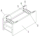
FIG. 1 is a schematic structural view of the present invention;
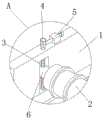
FIG. 2 is an enlarged view of FIG. A in FIG. 1;
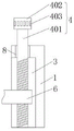
FIG. 3 is a detailed view of the structure adjusting mechanism of the present invention;
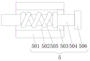
FIG. 4 is a detailed view of the structure fixing device of the present invention;
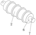
fig. 5 is a perspective view of the structure wire pressing wheel of the present invention.
In the figure: 1. a wire pressing machine body; 2. a wire pressing wheel; 3. a square groove; 4. an adjustment mechanism; 401. a threaded rod; 402. a rotation knob; 403. a circular fixing groove; 5. a fixing device; 501. a fixed block; 502. a circular through hole; 503. a limiting block; 504. fixing the rod; 505. a spring; 506. lifting the handle; 6. a connecting rod; 7. a threaded through hole; 8. and a bearing.
Detailed Description
The technical solutions in the embodiments of the present invention will be described clearly and completely with reference to the accompanying drawings in the embodiments of the present invention, and it is obvious that the described embodiments are only some embodiments of the present invention, not all embodiments. Based on the embodiments in the present invention, all other embodiments obtained by a person skilled in the art without creative work belong to the protection scope of the present invention.
Referring to fig. 1-5, an adjusting mechanism for a wire pressing wheel of a steel bar winding machine comprises a wire pressing machine body 1, two wire pressing wheels 2 are fixedly mounted on the inner wall of the wire pressing machine body 1, square grooves 3 are formed in the front and the back of the inner wall of the top of the wire pressing machine body 1, adjusting mechanisms 4 are fixedly mounted inside the four square grooves 3, the four adjusting mechanisms 4 are in threaded connection with the left side and the right side of the two wire pressing wheels 2, four fixing devices 5 are fixedly mounted on the top of the wire pressing machine body 1, and the four fixing devices 5 are located on the right side of the adjusting mechanisms 4.
Further, the front and the back of the left side wire pressing wheel 2 are all rotated and are connected with the connecting rod 6, the threaded through hole 7 is all seted up at the top of two connecting rods 6, rotate through the left and right sides at the wire pressing wheel 2 and be connected with the connecting rod 6, the threaded through hole 7 is seted up in the inside of connecting rod 6 simultaneously and is realized in the threaded connection of threaded rod 401, realization that just so can be fine is to the regulation of wire pressing wheel 2, just so can be adapted to the reinforcing bar of different diameters, make the effect of adjusting better.
Further, adjustment mechanism 4 includes threaded rod 401, threaded rod 401's bottom is rotated with square groove 3's bottom and is connected, threaded rod 401's surface and thread through hole 7 threaded connection, threaded rod 401's top is run through wire pressing machine body 1 and is extended to wire pressing machine body 1's top, threaded rod 401's top fixedly connected with knob 402, the circular fixed slot 403 that the equidistance was arranged is seted up to knob 402's surface, realize whole adjustment mechanism 4's power supply through manpower rotatory knob 402, knob 402 drives threaded rod 401 rotatory simultaneously, thereby it adjusts the height of wire pressing wheel 2 to realize the reinforcing bar according to different diameters, it realizes realizing the fixed with dead lever 504 to set up circular fixed slot 403 at knob 402's surface simultaneously, just so can guarantee knob 402's stability, make the effect of adjusting better.
Further, the fixing device 5 comprises a fixing block 501, the bottom of the fixing block 501 is fixedly connected with the top of the wire pressing machine body 1, a circular through hole 502 is formed in the fixing block 501, a limiting block 503 is fixedly installed at the right opening of the circular through hole 502, a fixing rod 504 is slidably connected in the limiting block 503, a spring 505 is sleeved on the outer surface of the fixing rod 504, the right side of the spring 505 is fixedly connected with the left side of the limiting block 503, the left side of the fixing rod 504 is connected with the circular fixing groove 403 in an inserting mode, the right side of the fixing rod 504 penetrates through the circular through hole 502 and extends to the right side of the fixing block 501, a lifting handle 506 is fixedly connected to the right side of the fixing rod 504, the power source of the whole fixing device 5 is achieved by manually pulling the lifting handle 506, meanwhile, the lifting handle 506 drives, the action of the force is mutual, so when the height is adjusted to a required height, the spring 505 provides a reaction force which is the same as that of the fixing rod 504, and thus the fixing rod 504 and the circular fixing groove 403 can be quickly inserted, the adjusting process is more stable, and the adjusting effect is better.
Further, bearing 8 is inlayed at the top of wire pressing machine body 1, and the interior circle of bearing 8 is connected with the surface fixed connection of threaded rod 401, inlays through the top of wire pressing machine body 1 and is equipped with bearing 8, and the interior circle of bearing 8 is connected with the surface fixed connection of threaded rod 401 simultaneously, just so can guarantee give the power of fixing with threaded rod 401 when not influencing threaded rod 401 normal rotation, makes the effect of adjusting better.
Further, the outer fixed surface of knob 402 is connected with the slipmat, and the slipmat is the silica gel slipmat, through the outer fixed surface at knob 402 is connected with the slipmat, just so can realize when the hand perspires, realizes preliminary antiskid, is the silica gel slipmat at the slipmat simultaneously, just so can realize further antiskid, makes skid-proof effect better, makes the effect of adjusting also better simultaneously.
The working principle is as follows: firstly, the extrusion of the reinforcing steel bars is realized by fixedly mounting two wire pressing wheels 2 at the top of a wire pressing machine body 1, meanwhile, four square grooves 3 are arranged in the wire pressing machine body 1 to realize the storage of an adjusting mechanism 4, the power source of the whole adjusting mechanism 4 is realized by manually rotating a rotary button 402, simultaneously, the rotary button 402 drives a threaded rod 401 to rotate, thereby realizing the adjustment of the height of the wire pressing wheels 2 according to the reinforcing steel bars with different diameters, meanwhile, a round fixing groove 403 is arranged on the outer surface of the rotary button 402 to realize the fixation with a fixing rod 504, thus, the stability of the rotary button 402 can be ensured, the adjusting effect is better, thus, the extrusion can be realized by adjusting different heights according to the reinforcing steel bars with different diameters, the extruding effect is better, and the power source of the whole fixing device 5 is realized by manually pulling a lifting handle 506, meanwhile, the handle 506 is lifted to drive the fixing rod 504 to move, the fixing rod 504 moves while the same moving force is given to the spring 505, and due to the fact that the forces are mutual, when the height is adjusted to be required, the spring 505 gives the same reacting force as the fixing rod 504, the fixing rod 504 can be rapidly inserted into the circular fixing groove 403, the adjusting process is stable, and therefore the reinforcing steel bar can be adapted to reinforcing steel bars with different diameters.
It is noted that, herein, relational terms such as first and second, and the like may be used solely to distinguish one entity or action from another entity or action without necessarily requiring or implying any actual such relationship or order between such entities or actions. Also, the terms "comprises," "comprising," or any other variation thereof, are intended to cover a non-exclusive inclusion, such that a process, method, article, or apparatus that comprises a list of elements does not include only those elements but may include other elements not expressly listed or inherent to such process, method, article, or apparatus.
Although embodiments of the present invention have been shown and described, it will be appreciated by those skilled in the art that changes, modifications, substitutions and alterations can be made in these embodiments without departing from the principles and spirit of the invention, the scope of which is defined in the appended claims and their equivalents.
Claims (6)
1. The utility model provides an adjustment mechanism of steel bar coiling machine fabric wheel, includes fabric wheel body (1), its characterized in that: fixed mounting has two fabric rollers (2) on the inner wall of fabric roller body (1), square groove (3), four have all been seted up at the front and the back of fabric roller body (1) top inner wall the equal fixed mounting in inside of square groove (3) has adjustment mechanism (4), four adjustment mechanism (4) and two fabric rollers's (2) both sides threaded connection about, the top fixed mounting of fabric roller body (1) has four fixing device (5), four fixing device (5) all are located the right side of adjustment mechanism (4).
2. The adjusting mechanism of the wire pressing wheel of the steel bar winding machine according to claim 1, characterized in that: the front and the back of the wire pressing wheel (2) on the left side are both rotatably connected with a connecting rod (6), and threaded through holes (7) are formed in the tops of the connecting rods (6).
3. The adjusting mechanism of the wire pressing wheel of the steel bar winding machine according to claim 1, characterized in that: adjustment mechanism (4) include threaded rod (401), the bottom of threaded rod (401) is rotated with the bottom of square groove (3) and is connected, the surface and screw through hole (7) threaded connection of threaded rod (401), the top of threaded rod (401) is run through line ball machine body (1) and is extended to the top of line ball machine body (1), the top fixedly connected with knob (402) of threaded rod (401), circular fixed slot (403) that the equidistance was arranged are seted up to the surface of knob (402).
4. The adjusting mechanism of the wire pressing wheel of the steel bar winding machine according to claim 1, characterized in that: fixing device (5) include fixed block (501), the bottom of fixed block (501) and the top fixed connection of wire pressing machine body (1), circular through-hole (502) have been seted up to the inside of fixed block (501), the right side opening part fixed mounting of circular through-hole (502) has stopper (503), the inside sliding connection of stopper (503) has dead lever (504), the surface cover of dead lever (504) is equipped with spring (505), the right side of spring (505) and the left side fixed connection of stopper (503), the left side and the circular fixed slot (403) of dead lever (504) are pegged graft, the right side of dead lever (504) runs through circular through-hole (502) and extends to the right side of fixed block (501), the right side fixedly connected with of dead lever (504) carries pull handle (506).
5. The adjusting mechanism of the wire pressing wheel of the steel bar winding machine according to claim 3, characterized in that: the wire pressing machine is characterized in that a bearing (8) is embedded in the top of the wire pressing machine body (1), and the inner circle of the bearing (8) is fixedly connected with the outer surface of the threaded rod (401).
6. The adjusting mechanism of the wire pressing wheel of the steel bar winding machine according to claim 3, characterized in that: the outer surface of the rotating button (402) is fixedly connected with an anti-slip pad, and the anti-slip pad is a silica gel anti-slip pad.
Priority Applications (1)
| Application Number | Priority Date | Filing Date | Title |
|---|---|---|---|
| CN201921310611.0U CN210848097U (en) | 2019-08-14 | 2019-08-14 | Adjusting mechanism of steel bar winding machine wire pressing wheel |
Applications Claiming Priority (1)
| Application Number | Priority Date | Filing Date | Title |
|---|---|---|---|
| CN201921310611.0U CN210848097U (en) | 2019-08-14 | 2019-08-14 | Adjusting mechanism of steel bar winding machine wire pressing wheel |
Publications (1)
| Publication Number | Publication Date |
|---|---|
| CN210848097U true CN210848097U (en) | 2020-06-26 |
Family
ID=71302771
Family Applications (1)
| Application Number | Title | Priority Date | Filing Date |
|---|---|---|---|
| CN201921310611.0U Expired - Fee Related CN210848097U (en) | 2019-08-14 | 2019-08-14 | Adjusting mechanism of steel bar winding machine wire pressing wheel |
Country Status (1)
| Country | Link |
|---|---|
| CN (1) | CN210848097U (en) |
Cited By (1)
| Publication number | Priority date | Publication date | Assignee | Title |
|---|---|---|---|---|
| CN113426922A (en) * | 2021-05-28 | 2021-09-24 | 攀枝花市巨麦钛业有限责任公司 | Bending moment adjustable material pressing equipment |
-
2019
- 2019-08-14 CN CN201921310611.0U patent/CN210848097U/en not_active Expired - Fee Related
Cited By (1)
| Publication number | Priority date | Publication date | Assignee | Title |
|---|---|---|---|---|
| CN113426922A (en) * | 2021-05-28 | 2021-09-24 | 攀枝花市巨麦钛业有限责任公司 | Bending moment adjustable material pressing equipment |
Similar Documents
| Publication | Publication Date | Title |
|---|---|---|
| CN211419083U (en) | Cable winding device | |
| CN216736925U (en) | Winding-up device with adjustable electric power engineering is used | |
| CN219525891U (en) | Winding device for electrical engineering design | |
| CN216711188U (en) | Winding machine for producing chemical fiber | |
| CN218619581U (en) | Cable arranging machine for cable production | |
| CN218319731U (en) | Rolling machine is used in cotton production and processing of pearl | |
| CN219464434U (en) | Dual-drive intelligent plate bending machine | |
| CN215625870U (en) | Insulated wire coiling device | |
| CN216583485U (en) | Take-up device for cable production | |
| CN214956193U (en) | Special automatic stranding machine of electrician convenient to adjust | |
| CN211860666U (en) | PCB forming machine for electronic industrial equipment | |
| CN220382638U (en) | Wire harness peeling device | |
| CN214989300U (en) | Coiling machine is used in cable wire manufacturing | |
| CN220564027U (en) | Winding roll | |
| CN207792326U (en) | A kind of adjustable for height vertical cable coiling device | |
| CN216150703U (en) | Wire drawing machine is used in copper wire processing with draw gear | |
| CN218159976U (en) | Winding device for inductor production | |
| CN216889492U (en) | Winder with leveling function for producing polyester fiber ropes | |
| CN211310435U (en) | Gantry type cable wire take-up and pay-off machine | |
| CN221352563U (en) | Winding machine | |
| CN223770879U (en) | Wire collecting device of fork type wire twisting machine | |
| CN212967244U (en) | Preparation device of cable core | |
| CN207192460U (en) | The take-up of machine is stretched in a kind of | |
| CN223180959U (en) | Electronic transformer winding device | |
| CN215143444U (en) | Wire drawing machine for producing low-voltage cable |
Legal Events
| Date | Code | Title | Description |
|---|---|---|---|
| GR01 | Patent grant | ||
| GR01 | Patent grant | ||
| TR01 | Transfer of patent right | ||
| TR01 | Transfer of patent right |
Effective date of registration: 20210728 Address after: 315000 Wangjiaqiao Village, Dongqiao Town, Haishu District, Ningbo City, Zhejiang Province Patentee after: Ningbo Newland automation equipment Co.,Ltd. Address before: 518100 floor 3, building C, Wanfeng venture industrial park, Shajing street, Bao'an District, Shenzhen, Guangdong Patentee before: Huang Yongjun |
|
| CF01 | Termination of patent right due to non-payment of annual fee | ||
| CF01 | Termination of patent right due to non-payment of annual fee |
Granted publication date: 20200626 Termination date: 20210814 |