CN210847487U - A rubber eraser - Google Patents
A rubber eraser Download PDFInfo
- Publication number
- CN210847487U CN210847487U CN201921690451.7U CN201921690451U CN210847487U CN 210847487 U CN210847487 U CN 210847487U CN 201921690451 U CN201921690451 U CN 201921690451U CN 210847487 U CN210847487 U CN 210847487U
- Authority
- CN
- China
- Prior art keywords
- fixedly connected
- electrostatic adsorption
- top surface
- adsorption plate
- installation groove
- Prior art date
- Legal status (The legal status is an assumption and is not a legal conclusion. Google has not performed a legal analysis and makes no representation as to the accuracy of the status listed.)
- Expired - Fee Related
Links
Images


Landscapes
- Nozzles For Electric Vacuum Cleaners (AREA)
Abstract
本实用新型涉及清洁用具技术领域,且公开了一种橡皮擦除尘器,包括上盖、槽体、下盖、连杆机构、静电吸附板、除尘滑块、伸缩机构、侧板和弹簧,通过静电发生器和静电吸附板的设置,利用静电的吸附力进行除尘,相较于风力吸附能够更有效的将细小灰尘进行集中收集,工作时全程无噪音且不会损伤到叶片等物品;静电发生器相较于变压器作为动力源,耗电量小且更体积、重量也更小,有利于进行缩小除尘器体积的设计,通过静电吸附板的设置,能快速去除吸附于其上的灰尘碎屑,综合使用效率很高,灰尘吸附效果好,不会散发到空中,更加环保。
The utility model relates to the technical field of cleaning utensils, and discloses a rubber eraser, which comprises an upper cover, a groove body, a lower cover, a link mechanism, an electrostatic adsorption plate, a dust removal slider, a telescopic mechanism, a side plate and a spring. The electrostatic generator and the electrostatic adsorption plate are set up to use the electrostatic adsorption force for dust removal. Compared with the wind adsorption, the fine dust can be collected more effectively. There is no noise during the whole process and will not damage the blades and other items; static electricity occurs. Compared with the transformer as a power source, the precipitator consumes less power and is larger in size and weight, which is conducive to the design of reducing the size of the precipitator. Through the setting of the electrostatic adsorption plate, the dust and debris adsorbed on it can be quickly removed. , The comprehensive use efficiency is very high, the dust adsorption effect is good, and it will not be emitted into the air, which is more environmentally friendly.
Description
技术领域technical field
本实用新型涉及清洁用具技术领域,具体为一种橡皮擦除尘器。The utility model relates to the technical field of cleaning appliances, in particular to a rubber duster.
背景技术Background technique
现有的橡皮擦除尘器一般都是通过涡轮增压电机产生负压,起动清理作用,但是这种设备的电耗大,灰尘容易粘在过滤网、毛刷吸管、集尘缸上,除尘效率低下,体积大,不利于学生携带除尘效果不佳。为此,人们设计出一种利用微型电机带动叶片旋转产生压力差的方式除尘,灰尘容易粘在叶片、过滤网上,能耗降低,利用干电池储能,但不符合绿色理念。为了解决这些问题,人们发明了很多利用压力差原理设计成的吸尘器,如公开号为CN109130630A的中国专利,公开了一种自动除尘器,其特征在于,包括:壳体、风扇、电池、滤网、盖和橡皮擦,通过风扇旋转轴带动橡皮固定座与橡皮擦一同旋转,通过旋转的橡皮擦擦除错误书写处,通过风扇产生的回旋风将灰尘和污垢吸入吸尘室,克服了原橡皮擦容易擦破书本,擦后用口吹或者手抹和污垢不卫生和不环保的问题。但并没有解决细小灰尘容易粘到叶片上的问题;公开号为CN2649353Y的中国专利,公开了一种电动吸尘器,其特征在于,包括壳体、电机、充电变压器、橡皮擦组成,壳体的前部为吸尘室,壳体后部设有橡皮擦槽,橡皮擦槽内设有橡皮座,橡皮座通过弹性轮活动固定壳体上,壳体上还设有笔刀槽以及时钟,该专利具有方便卫生、结构简单的特点。但该实用新型装有变压器,耗电量大。因此亟需一种橡皮擦除尘器来解决上述问题。Existing rubber dust collectors generally generate negative pressure through a turbocharged motor to start cleaning, but this equipment consumes a lot of electricity, and dust is easy to stick to the filter screen, brush suction pipe, and dust collection cylinder. Low, bulky, not conducive to students to carry the dust removal effect is not good. To this end, people have designed a way to remove dust by using a micro-motor to drive the blades to rotate to generate a pressure difference. The dust is easy to stick to the blades and the filter net, and the energy consumption is reduced. The dry battery is used for energy storage, but it does not meet the green concept. In order to solve these problems, people have invented many vacuum cleaners designed using the principle of pressure difference. For example, the Chinese patent with publication number CN109130630A discloses an automatic dust collector, which is characterized in that it includes: a casing, a fan, a battery, a filter screen , cover and eraser, the eraser holder and eraser are driven by the rotating shaft of the fan to rotate together, the wrong writing is erased by the rotating eraser, and the dust and dirt are sucked into the vacuum chamber by the whirlwind generated by the fan, which overcomes the problem of the original eraser. Wiping is easy to scratch the book, and it is unsanitary and environmentally friendly to blow by mouth or hand wipe after wiping. However, it does not solve the problem that fine dust is easy to stick to the blade; the Chinese patent with publication number CN2649353Y discloses an electric vacuum cleaner, which is characterized in that it includes a casing, a motor, a charging transformer, and an eraser. The front of the casing is composed of The part is a vacuuming room, the rear of the casing is provided with an eraser groove, and a rubber seat is arranged in the eraser groove. The rubber seat is fixed on the casing through elastic wheels. It has the characteristics of convenience, hygiene and simple structure. However, the utility model is equipped with a transformer, which consumes a large amount of electricity. Therefore, there is an urgent need for a rubber eraser to solve the above problems.
实用新型内容Utility model content
(一)解决的技术问题(1) Technical problems solved
针对现有技术的不足,本实用新型提供了一种橡皮擦除尘器,具备综合使用效率高、体积小,成本低,无噪音等优点,解决了现有的橡皮擦除尘器存在的各种使用不方便的问题。In view of the deficiencies of the prior art, the utility model provides an eraser duster, which has the advantages of high comprehensive use efficiency, small size, low cost, no noise, etc., and solves the various uses of the existing eraser duster. inconvenient question.
(二)技术方案(2) Technical solutions
为实现上述综合使用效率高、体积小,成本低,无噪音目的,本实用新型提供如下技术方案:一种橡皮擦除尘器,包括上盖、槽体、下盖、连杆机构、静电吸附板、除尘滑块、伸缩机构、侧板和弹簧,槽体的形状呈倒置的L型体且内部中空,槽体的底面开设有安装槽A和安装槽B,安装槽B对应安装槽A的一面相互连通,安装槽A内开设有两个环孔,静电吸附板固定安装于安装槽A 内,静电吸附板背离安装槽A的一面铺设有毛刷,槽体内部固定安装有静电发生器,静电发生器通过环孔与静电吸附板电性连接,弹簧固定连接安装槽B的顶面内壁,弹簧未固定的一端与伸缩机构固定连接,伸缩机构由两组限位板、接触块、拉杆、活动块和连接柱组成,两组限位板均固定连接在安装槽B内,两组限位板呈左右对应,每组限位板的数量为两个,每组的两个限位板呈前后对应且中心留有间距,弹簧位于右侧一组的两个限位板之间,接触块为顶面设有圆柱凸起的矩形体,接触块的尺寸与每组两个限位板之间的间距相适配,接触块的底面与弹簧固定连接,活动块的形状成矩形体,活动块位于左侧一组的两个限位板之间,活动块的尺寸与每组两个限位板之间的间距相适配,活动块与接触块相对应的一面均设有矩形凸起,矩形凸起上设有圆杆,拉杆的形状呈矩形体且两端开设有圆孔,拉杆的两端分别与接触块和活动块上的圆杆套接活动块远离拉杆的一面与连接柱固定连接,连接柱穿过安装槽A与安装槽B连通处的孔,连杆机构固定安装于静电吸附板背离安装槽A的一面,连杆机构与连接柱固定连接,连杆机构采用连杆伸缩机构,连杆机构远离伸缩机构的一端与除尘滑块固定连接,除尘滑块与静电吸附板贴合。In order to achieve the above-mentioned purposes of high comprehensive use efficiency, small size, low cost and no noise, the present utility model provides the following technical solutions: an eraser duster, comprising an upper cover, a groove body, a lower cover, a connecting rod mechanism, and an electrostatic adsorption plate , Dust removal slider, telescopic mechanism, side plate and spring. The shape of the tank body is an inverted L-shaped body and the interior is hollow. The bottom surface of the tank body is provided with a mounting slot A and a mounting slot B, and the mounting slot B corresponds to the side of the mounting slot A. They are connected to each other. There are two ring holes in the installation slot A. The electrostatic adsorption plate is fixedly installed in the installation slot A. The side of the electrostatic adsorption plate away from the installation slot A is laid with a brush. The generator is electrically connected to the electrostatic adsorption plate through the ring hole, the spring is fixedly connected to the inner wall of the top surface of the installation slot B, and the unfixed end of the spring is fixedly connected to the telescopic mechanism, which consists of two sets of limit plates, contact blocks, pull rods, movable It consists of a block and a connecting column. The two sets of limit plates are fixedly connected in the installation slot B. The two sets of limit plates correspond to the left and right. Correspondingly and with a gap in the center, the spring is located between the two limit plates of the right group, the contact block is a rectangular body with a cylindrical protrusion on the top surface, and the size of the contact block is between the two limit plates of each group. The distance of the contact block is adapted, the bottom surface of the contact block is fixedly connected with the spring, the shape of the movable block is a rectangle, and the movable block is located between the two limit plates of the left group. The spacing between the plates is adapted, and the side corresponding to the movable block and the contact block is provided with a rectangular protrusion, a round rod is provided on the rectangular protrusion, the shape of the pull rod is a rectangular body and round holes are opened at both ends, and the The two ends are respectively connected with the contact block and the circular rod on the movable block. The side of the movable block away from the tie rod is fixedly connected to the connecting column. The connecting column passes through the hole where the installation slot A and the installation slot B communicate with each other. The connecting rod mechanism is fixedly installed on the electrostatic The side of the adsorption plate facing away from the installation slot A, the connecting rod mechanism is fixedly connected with the connecting column, the connecting rod mechanism adopts the connecting rod telescopic mechanism, the end of the connecting rod mechanism away from the telescopic mechanism is fixedly connected with the dust removal slider, and the dust removal slider is attached to the electrostatic adsorption plate. combine.
侧板的顶面开设有穿孔,侧板与安装槽B的内壁固定连接,接触块位于穿孔内。The top surface of the side plate is provided with a perforation, the side plate is fixedly connected with the inner wall of the installation slot B, and the contact block is located in the perforation.
槽体的顶面固定安装有拨动开关,拨动开关与静电发生器电性连接,上盖固定安装与槽体的顶面,上盖的顶面开设有开关槽,拨动开关位于开关槽内。A toggle switch is fixedly installed on the top surface of the tank body. The toggle switch is electrically connected to the electrostatic generator. The upper cover is fixedly installed on the top surface of the tank body. The top surface of the upper cover is provided with a switch slot, and the toggle switch is located in the switch slot. Inside.
下盖的顶面固定连接有顶块,下盖的顶面固定连接有卡合框,下盖通过卡合框与安装槽A的卡合固定连接在槽体的底面。The top surface of the lower cover is fixedly connected with a top block, the top surface of the lower cover is fixedly connected with an engaging frame, and the lower cover is fixedly connected to the bottom surface of the tank body through the engaging of the engaging frame and the installation slot A.
优选的,所述侧板的形状和尺寸与安装槽B一致。Preferably, the shape and size of the side plate are consistent with the installation slot B.
优选的,所述卡合框的尺寸与安装槽A内壁的尺寸相适配。Preferably, the size of the engaging frame is adapted to the size of the inner wall of the installation slot A.
优选的,所述顶块的形状和尺寸与穿孔一致且位置对应。Preferably, the shape and size of the top block are consistent with the perforations and the positions thereof are corresponding.
(三)有益效果(3) Beneficial effects
与现有技术相比,本实用新型提供了一种橡皮擦除尘器,具备以下有益效果:Compared with the prior art, the utility model provides an eraser duster, which has the following beneficial effects:
1、该橡皮擦除尘器,通过静电发生器和静电吸附板的设置,利用静电的吸附力进行除尘,相较于风力吸附能够更有效的将细小灰尘进行集中收集,工作时全程无噪音且不会损伤到叶片等物品;静电发生器相较于变压器作为动力源,耗电量小且更体积、重量也更小,有利于进行缩小除尘器体积的设计。1. The rubber dust remover uses the electrostatic adsorption force to remove dust through the setting of the electrostatic generator and the electrostatic adsorption plate. Compared with the wind adsorption, it can collect the fine dust more effectively, and the whole process is noise-free and does not work. It will damage the blades and other items; compared with the transformer as a power source, the electrostatic generator consumes less power and is larger in size and weight, which is conducive to the design of reducing the size of the precipitator.
2、该橡皮擦除尘器,通过槽体的设置,在使用时的操作仿照橡皮擦的方式,无须用力且无须寻找灰尘的位置,在物体上轻轻推动即可达到较好的清理效果,有着广泛的使用范围,且通过静电吸附板上毛刷的设置,能够大大增加静电吸附的范围以及效果。2. The eraser dust remover, through the setting of the tank body, operates in the same way as an eraser when in use. It does not require force and does not need to find the position of the dust. It can achieve a better cleaning effect by gently pushing it on the object. Wide range of use, and through the setting of brushes on the electrostatic adsorption plate, the range and effect of electrostatic adsorption can be greatly increased.
附图说明Description of drawings
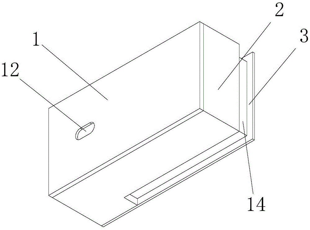
图1为本实用新型的结构示意图;Fig. 1 is the structural representation of the utility model;
图2为本实用新型槽体的底面结构示意图;Fig. 2 is the bottom surface structure schematic diagram of the groove body of the utility model;
图3为本实用新型槽体的底面结构示意图;Fig. 3 is the bottom surface structure schematic diagram of the groove body of the utility model;
图4为本实用新型静电吸附板和伸缩机构的结构示意图;4 is a schematic structural diagram of an electrostatic adsorption plate and a telescopic mechanism of the present invention;
图5为本实用新型槽体的底面结构示意图;5 is a schematic diagram of the bottom surface structure of the tank body of the present invention;
图6为本实用新型下盖的结构示意图;Fig. 6 is the structural representation of the lower cover of the present invention;
图7为本实用新型图4的A处放大图。FIG. 7 is an enlarged view of part A of FIG. 4 of the present utility model.
图中:1上盖、2槽体、3下盖、4连杆机构、5静电吸附板、6除尘滑块、 7伸缩机构、71限位板、72接触块、73拉杆、74活动块、75连接柱、8侧板、 9弹簧、10安装槽A、11安装槽B、12开关槽、13环孔、14卡合框、15穿孔、 16顶块、17矩形凸起。In the picture: 1 upper cover, 2 tank body, 3 lower cover, 4 linkage mechanism, 5 electrostatic adsorption plate, 6 dust removal slider, 7 telescopic mechanism, 71 limit plate, 72 contact block, 73 pull rod, 74 movable block, 75 connecting posts, 8 side plates, 9 springs, 10 installation slots A, 11 installation slots B, 12 switch slots, 13 ring holes, 14 snap frames, 15 perforations, 16 top blocks, 17 rectangular protrusions.
具体实施方式Detailed ways
下面将结合本实用新型实施例中的附图,对本实用新型实施例中的技术方案进行清楚、完整地描述,显然,所描述的实施例仅仅是本实用新型一部分实施例,而不是全部的实施例。基于本实用新型中的实施例,本领域普通技术人员在没有做出创造性劳动前提下所获得的所有其他实施例,都属于本实用新型保护的范围。The technical solutions in the embodiments of the present utility model will be clearly and completely described below with reference to the accompanying drawings in the embodiments of the present utility model. Obviously, the described embodiments are only a part of the embodiments of the present utility model, rather than all the implementations. example. Based on the embodiments of the present invention, all other embodiments obtained by those of ordinary skill in the art without creative work fall within the protection scope of the present invention.
请参阅图1-7,本实用新型提出了一种橡皮擦除尘器,包括上盖1、槽体2、下盖3、连杆机构4、静电吸附板5、除尘滑块6、伸缩机构7、侧板8和弹簧9,槽体2的形状呈倒置的L型体且内部中空,槽体2的底面开设有安装槽A10和安装槽B11,安装槽B11对应安装槽A10的一面相互连通,安装槽A10内开设有两个环孔13,静电吸附板5固定安装于安装槽A10内,静电吸附板5背离安装槽A10的一面铺设有毛刷,槽体2内部固定安装有静电发生器,静电发生器为现有公知技术,在此不做赘述,静电发生器通过环孔13与静电吸附板5电性连接,弹簧9固定连接安装槽B11的顶面内壁,弹簧9未固定的一端与伸缩机构7 固定连接,伸缩机构7由两组限位板71、接触块72、拉杆73、活动块74和连接柱75组成,两组限位板71均固定连接在安装槽B11内,两组限位板71呈左右对应,每组限位板71的数量为两个,每组的两个限位板71呈前后对应且中心留有间距,弹簧位于右侧一组的两个限位板71之间,接触块72为顶面设有圆柱凸起的矩形体,接触块72的尺寸与每组两个限位板71之间的间距相适配,接触块72的底面与弹簧固定连接,活动块74的形状成矩形体,活动块74位于左侧一组的两个限位板71之间,活动块74的尺寸与每组两个限位板71之间的间距相适配,活动块74与接触块72相对应的一面均设有矩形凸起17,矩形凸起17上设有圆杆,拉杆73的形状呈矩形体且两端开设有圆孔,拉杆73的两端分别与接触块72和活动块74上的圆杆套接活动块74远离拉杆73的一面与连接柱75固定连接,连接柱75穿过安装槽A10与安装槽B11连通处的孔,弹簧9 呈弹起状态时,带动接触块72抬起且使拉杆73由横置向竖置转换,拉杆73运动时对活动块74产生拉动,带动活动块74向接触块72滑动,当接触块72受力下压时,带动拉杆73由竖置向横置转换且对活动块74产生推动,带动活动块74向远离接触块72的方向滑动,连杆机构4固定安装于静电吸附板5背离安装槽A10的一面,连杆机构4与连接柱75固定连接,连杆机构4采用连杆伸缩机构,连杆机构4通过连接柱75的左右滑动来切换展开和收缩的两种状态,其为现有公知技术,在此不再赘述,连杆机构4远离伸缩机构7的一端与除尘滑块6固定连接,除尘滑块6呈矩形体,除尘滑块6的宽度与安装槽A10的宽度一致,除尘滑块6与静电吸附板5贴合。Please refer to FIGS. 1-7 , the utility model proposes a rubber dust remover, including an
侧板8的形状和尺寸与安装槽B11一致,侧板8的顶面开设有穿孔15,侧板8与安装槽B11的内壁固定连接,接触块72位于穿孔15内。The shape and size of the side plate 8 are consistent with the installation slot B11 , the top surface of the side plate 8 is provided with a through
槽体2的顶面固定安装有拨动开关,拨动开关与静电发生器电性连接,上盖1固定安装与槽体2的顶面,上盖1的顶面开设有开关槽12,拨动开关位于开关槽12内。A toggle switch is fixedly installed on the top surface of the
下盖3的顶面固定连接有顶块16,顶块16的形状和尺寸与穿孔15一致且位置对应,下盖3的顶面固定连接有卡合框14,卡合框14的尺寸与安装槽A10 内壁的尺寸相适配,下盖3通过卡合框14与安装槽A10的卡合固定连接在槽体 2的底面,下盖3与槽体2固定连接时,顶块16在穿孔15内对接触块72进行推动,带动弹簧9收缩对活动块74产生推动,使得连杆机构4呈收缩状态,下盖3脱离槽体2时,弹簧9回弹带动接触块72抬起,拉动活动块74,使得连杆机构4呈展开状态。The top surface of the
在使用时,第一步,打开下盖3使顶块16与伸缩机构7脱离连接,弹簧9 将伸缩机构7顶起,使连杆机构4呈展开状态。In use, the first step is to open the
第二步,打开拨动开关,启动静电发生器,静电吸附板5上积蓄静电,手持槽体2后用带毛刷的静电吸附板5在桌子上除尘,通过静电将灰尘吸附到静电吸附板5上。In the second step, turn on the toggle switch and start the electrostatic generator. Static electricity is accumulated on the
第三步,关上下盖3,顶块16对伸缩机构7产生推动,带动连杆机构4呈收缩状态,除尘滑块6随着连杆机构4的收缩刮去吸附在静电吸附板5上的灰尘,掉落入下盖3中。In the third step, close the upper and
第四步,关闭拨动开关,静电吸附板5失去静电积蓄,使剩余未刮擦下来的灰尘落入下盖3上。In the fourth step, the toggle switch is turned off, and the
第五步,打开下盖3,伸缩机构7从缩紧状态变为展开状态,除尘滑块6再一次将灰尘刮落下盖3中,倒出下盖3中的垃圾入垃圾桶,合上下盖3。The fifth step, open the
尽管已经示出和描述了本实用新型的实施例,对于本领域的普通技术人员而言,可以理解在不脱离本实用新型的原理和精神的情况下可以对这些实施例进行多种变化、修改、替换和变型,本实用新型的范围由所附权利要求及其等同物限定。Although the embodiments of the present invention have been shown and described, it will be understood by those skilled in the art that various changes and modifications can be made to these embodiments without departing from the principles and spirit of the present invention , alternatives and modifications, the scope of the present invention is defined by the appended claims and their equivalents.
Claims (4)
Priority Applications (1)
| Application Number | Priority Date | Filing Date | Title |
|---|---|---|---|
| CN201921690451.7U CN210847487U (en) | 2019-10-10 | 2019-10-10 | A rubber eraser |
Applications Claiming Priority (1)
| Application Number | Priority Date | Filing Date | Title |
|---|---|---|---|
| CN201921690451.7U CN210847487U (en) | 2019-10-10 | 2019-10-10 | A rubber eraser |
Publications (1)
| Publication Number | Publication Date |
|---|---|
| CN210847487U true CN210847487U (en) | 2020-06-26 |
Family
ID=71300606
Family Applications (1)
| Application Number | Title | Priority Date | Filing Date |
|---|---|---|---|
| CN201921690451.7U Expired - Fee Related CN210847487U (en) | 2019-10-10 | 2019-10-10 | A rubber eraser |
Country Status (1)
| Country | Link |
|---|---|
| CN (1) | CN210847487U (en) |
Cited By (1)
| Publication number | Priority date | Publication date | Assignee | Title |
|---|---|---|---|---|
| CN112838988A (en) * | 2020-12-11 | 2021-05-25 | 江苏德联达智能科技有限公司 | Router with low adsorptivity of dust |
-
2019
- 2019-10-10 CN CN201921690451.7U patent/CN210847487U/en not_active Expired - Fee Related
Cited By (1)
| Publication number | Priority date | Publication date | Assignee | Title |
|---|---|---|---|---|
| CN112838988A (en) * | 2020-12-11 | 2021-05-25 | 江苏德联达智能科技有限公司 | Router with low adsorptivity of dust |
Similar Documents
| Publication | Publication Date | Title |
|---|---|---|
| CN2592103Y (en) | Vertical dust collector | |
| CN116509238A (en) | Cleaning equipment and self-cleaning method thereof | |
| CN108185919A (en) | A kind of intelligent residence cleaning device | |
| CN116116159B (en) | A spray adsorption dust removal device in a building construction room | |
| CN211080056U (en) | Environment-friendly cleaning robot | |
| CN201280015Y (en) | Absorbent blackboard eraser convenient to discharge dust | |
| CN115253503B (en) | Bag type dust collector capable of reducing emission and use method | |
| CN213405900U (en) | A sweeping robot with mopping function | |
| CN201419599Y (en) | Electric dust absorption blackboard cleaning device | |
| CN210113490U (en) | Domestic air purifier convenient to clearance | |
| CN108720722A (en) | A kind of easy to clean Efficient dust collector | |
| CN108295561B (en) | A purifier filter screen dust removal method with good dust removal effect | |
| CN116353237B (en) | Electric vacuum blackboard eraser | |
| CN218899343U (en) | High-efficient dust collection robot sweeps floor | |
| CN2675032Y (en) | Electric vacuum cleaner | |
| CN205762878U (en) | A kind of school blackboard wipes cleaning device | |
| CN211834246U (en) | Dust box for sweeping robot and sweeping robot | |
| CN211676817U (en) | A wet dust removal device with environmental protection benefits | |
| CN219292293U (en) | Automatic cleaning device of hopper of bag collector | |
| CN223585853U (en) | Lightweight portable dust collector | |
| CN207856304U (en) | A toy with dust removal function | |
| CN2283455Y (en) | Cleaning head | |
| CN220757297U (en) | Dust collector convenient to clean | |
| CN112403106A (en) | V-shaped groove deep dust suction cleaner of plate filter not easy to deform | |
| CN217649197U (en) | Blackboard eraser with electrostatic absorbing chalk dust |
Legal Events
| Date | Code | Title | Description |
|---|---|---|---|
| GR01 | Patent grant | ||
| GR01 | Patent grant | ||
| CF01 | Termination of patent right due to non-payment of annual fee | ||
| CF01 | Termination of patent right due to non-payment of annual fee |
Granted publication date: 20200626 |