CN210845578U - Waste gas tar separation and filtration equipment - Google Patents
Waste gas tar separation and filtration equipment Download PDFInfo
- Publication number
- CN210845578U CN210845578U CN201921044227.0U CN201921044227U CN210845578U CN 210845578 U CN210845578 U CN 210845578U CN 201921044227 U CN201921044227 U CN 201921044227U CN 210845578 U CN210845578 U CN 210845578U
- Authority
- CN
- China
- Prior art keywords
- tar
- waste gas
- filtration
- main body
- filtering
- Prior art date
- Legal status (The legal status is an assumption and is not a legal conclusion. Google has not performed a legal analysis and makes no representation as to the accuracy of the status listed.)
- Expired - Fee Related
Links
- 238000001914 filtration Methods 0.000 title claims abstract description 127
- 239000002912 waste gas Substances 0.000 title claims abstract description 67
- 238000000926 separation method Methods 0.000 title claims abstract description 46
- 239000011269 tar Substances 0.000 title claims description 72
- 239000000463 material Substances 0.000 claims abstract description 20
- 239000007788 liquid Substances 0.000 claims abstract description 17
- 239000010865 sewage Substances 0.000 claims abstract description 8
- 239000011286 gas tar Substances 0.000 claims 3
- 230000010354 integration Effects 0.000 abstract description 4
- 230000000737 periodic effect Effects 0.000 abstract 1
- 239000010813 municipal solid waste Substances 0.000 description 70
- 239000007789 gas Substances 0.000 description 69
- OKTJSMMVPCPJKN-UHFFFAOYSA-N Carbon Chemical compound [C] OKTJSMMVPCPJKN-UHFFFAOYSA-N 0.000 description 50
- 238000000746 purification Methods 0.000 description 44
- XLYOFNOQVPJJNP-UHFFFAOYSA-N water Substances O XLYOFNOQVPJJNP-UHFFFAOYSA-N 0.000 description 33
- 239000002699 waste material Substances 0.000 description 23
- 238000005507 spraying Methods 0.000 description 21
- 238000000034 method Methods 0.000 description 19
- 229910052799 carbon Inorganic materials 0.000 description 18
- 239000007921 spray Substances 0.000 description 17
- 238000003763 carbonization Methods 0.000 description 16
- 238000001179 sorption measurement Methods 0.000 description 16
- 238000010438 heat treatment Methods 0.000 description 15
- 230000008569 process Effects 0.000 description 12
- 238000005516 engineering process Methods 0.000 description 11
- 239000000725 suspension Substances 0.000 description 10
- RYGMFSIKBFXOCR-UHFFFAOYSA-N Copper Chemical compound [Cu] RYGMFSIKBFXOCR-UHFFFAOYSA-N 0.000 description 9
- 229910052802 copper Inorganic materials 0.000 description 9
- 239000010949 copper Substances 0.000 description 9
- 230000006698 induction Effects 0.000 description 9
- 230000009471 action Effects 0.000 description 8
- QVGXLLKOCUKJST-UHFFFAOYSA-N atomic oxygen Chemical compound [O] QVGXLLKOCUKJST-UHFFFAOYSA-N 0.000 description 8
- 238000006243 chemical reaction Methods 0.000 description 8
- 239000001301 oxygen Substances 0.000 description 8
- 229910052760 oxygen Inorganic materials 0.000 description 8
- 238000001816 cooling Methods 0.000 description 7
- 238000007599 discharging Methods 0.000 description 7
- 239000002245 particle Substances 0.000 description 7
- 238000005192 partition Methods 0.000 description 7
- 238000000197 pyrolysis Methods 0.000 description 7
- UGFAIRIUMAVXCW-UHFFFAOYSA-N Carbon monoxide Chemical compound [O+]#[C-] UGFAIRIUMAVXCW-UHFFFAOYSA-N 0.000 description 6
- 239000000428 dust Substances 0.000 description 6
- 239000003546 flue gas Substances 0.000 description 6
- 230000005484 gravity Effects 0.000 description 6
- 238000012423 maintenance Methods 0.000 description 6
- 239000000123 paper Substances 0.000 description 6
- 239000000126 substance Substances 0.000 description 6
- HGUFODBRKLSHSI-UHFFFAOYSA-N 2,3,7,8-tetrachloro-dibenzo-p-dioxin Chemical compound O1C2=CC(Cl)=C(Cl)C=C2OC2=C1C=C(Cl)C(Cl)=C2 HGUFODBRKLSHSI-UHFFFAOYSA-N 0.000 description 5
- 230000005653 Brownian motion process Effects 0.000 description 5
- 229910000831 Steel Inorganic materials 0.000 description 5
- 230000008901 benefit Effects 0.000 description 5
- 238000005537 brownian motion Methods 0.000 description 5
- 230000000694 effects Effects 0.000 description 5
- 239000003344 environmental pollutant Substances 0.000 description 5
- 239000012535 impurity Substances 0.000 description 5
- 231100000719 pollutant Toxicity 0.000 description 5
- 239000010959 steel Substances 0.000 description 5
- 238000002485 combustion reaction Methods 0.000 description 4
- 230000007246 mechanism Effects 0.000 description 4
- 238000007790 scraping Methods 0.000 description 4
- 239000000779 smoke Substances 0.000 description 4
- UHOVQNZJYSORNB-UHFFFAOYSA-N Benzene Chemical compound C1=CC=CC=C1 UHOVQNZJYSORNB-UHFFFAOYSA-N 0.000 description 3
- QGJOPFRUJISHPQ-UHFFFAOYSA-N Carbon disulfide Chemical compound S=C=S QGJOPFRUJISHPQ-UHFFFAOYSA-N 0.000 description 3
- 239000004743 Polypropylene Substances 0.000 description 3
- YXFVVABEGXRONW-UHFFFAOYSA-N Toluene Chemical compound CC1=CC=CC=C1 YXFVVABEGXRONW-UHFFFAOYSA-N 0.000 description 3
- 239000003990 capacitor Substances 0.000 description 3
- 239000000919 ceramic Substances 0.000 description 3
- 238000005352 clarification Methods 0.000 description 3
- 210000000078 claw Anatomy 0.000 description 3
- 239000000498 cooling water Substances 0.000 description 3
- 238000004332 deodorization Methods 0.000 description 3
- 230000006872 improvement Effects 0.000 description 3
- 238000004519 manufacturing process Methods 0.000 description 3
- 229910052751 metal Inorganic materials 0.000 description 3
- 239000002184 metal Substances 0.000 description 3
- -1 methylthio hydrogen Chemical class 0.000 description 3
- 239000010815 organic waste Substances 0.000 description 3
- 238000007254 oxidation reaction Methods 0.000 description 3
- 230000002265 prevention Effects 0.000 description 3
- 238000012545 processing Methods 0.000 description 3
- 239000010453 quartz Substances 0.000 description 3
- 230000009467 reduction Effects 0.000 description 3
- VYPSYNLAJGMNEJ-UHFFFAOYSA-N silicon dioxide Inorganic materials O=[Si]=O VYPSYNLAJGMNEJ-UHFFFAOYSA-N 0.000 description 3
- 239000007787 solid Substances 0.000 description 3
- QGZKDVFQNNGYKY-UHFFFAOYSA-N Ammonia Chemical compound N QGZKDVFQNNGYKY-UHFFFAOYSA-N 0.000 description 2
- RWSOTUBLDIXVET-UHFFFAOYSA-N Dihydrogen sulfide Chemical compound S RWSOTUBLDIXVET-UHFFFAOYSA-N 0.000 description 2
- 206010021143 Hypoxia Diseases 0.000 description 2
- LSDPWZHWYPCBBB-UHFFFAOYSA-N Methanethiol Chemical compound SC LSDPWZHWYPCBBB-UHFFFAOYSA-N 0.000 description 2
- PPBRXRYQALVLMV-UHFFFAOYSA-N Styrene Chemical compound C=CC1=CC=CC=C1 PPBRXRYQALVLMV-UHFFFAOYSA-N 0.000 description 2
- 239000003463 adsorbent Substances 0.000 description 2
- 230000008859 change Effects 0.000 description 2
- 150000001875 compounds Chemical class 0.000 description 2
- 238000009833 condensation Methods 0.000 description 2
- 230000005494 condensation Effects 0.000 description 2
- 230000007797 corrosion Effects 0.000 description 2
- 238000005260 corrosion Methods 0.000 description 2
- 238000005520 cutting process Methods 0.000 description 2
- 238000013461 design Methods 0.000 description 2
- WQOXQRCZOLPYPM-UHFFFAOYSA-N dimethyl disulfide Chemical compound CSSC WQOXQRCZOLPYPM-UHFFFAOYSA-N 0.000 description 2
- 239000010791 domestic waste Substances 0.000 description 2
- 230000005684 electric field Effects 0.000 description 2
- 238000009713 electroplating Methods 0.000 description 2
- 238000004880 explosion Methods 0.000 description 2
- 238000007667 floating Methods 0.000 description 2
- 235000013305 food Nutrition 0.000 description 2
- 239000008187 granular material Substances 0.000 description 2
- 229910000037 hydrogen sulfide Inorganic materials 0.000 description 2
- 230000014759 maintenance of location Effects 0.000 description 2
- 238000012806 monitoring device Methods 0.000 description 2
- 239000003973 paint Substances 0.000 description 2
- 239000012466 permeate Substances 0.000 description 2
- 230000002035 prolonged effect Effects 0.000 description 2
- 238000005086 pumping Methods 0.000 description 2
- 238000004064 recycling Methods 0.000 description 2
- 238000005070 sampling Methods 0.000 description 2
- 239000007790 solid phase Substances 0.000 description 2
- GETQZCLCWQTVFV-UHFFFAOYSA-N trimethylamine Chemical compound CN(C)C GETQZCLCWQTVFV-UHFFFAOYSA-N 0.000 description 2
- QMMFVYPAHWMCMS-UHFFFAOYSA-N Dimethyl sulfide Chemical compound CSC QMMFVYPAHWMCMS-UHFFFAOYSA-N 0.000 description 1
- CTQNGGLPUBDAKN-UHFFFAOYSA-N O-Xylene Chemical compound CC1=CC=CC=C1C CTQNGGLPUBDAKN-UHFFFAOYSA-N 0.000 description 1
- 239000002253 acid Substances 0.000 description 1
- 239000000956 alloy Substances 0.000 description 1
- 229910021529 ammonia Inorganic materials 0.000 description 1
- 238000010923 batch production Methods 0.000 description 1
- 210000000988 bone and bone Anatomy 0.000 description 1
- 239000003054 catalyst Substances 0.000 description 1
- 229910002110 ceramic alloy Inorganic materials 0.000 description 1
- 239000007809 chemical reaction catalyst Substances 0.000 description 1
- 238000004581 coalescence Methods 0.000 description 1
- 239000011248 coating agent Substances 0.000 description 1
- 238000000576 coating method Methods 0.000 description 1
- 238000000748 compression moulding Methods 0.000 description 1
- 239000012141 concentrate Substances 0.000 description 1
- 238000010276 construction Methods 0.000 description 1
- 230000006837 decompression Effects 0.000 description 1
- 230000007423 decrease Effects 0.000 description 1
- 239000003657 drainage water Substances 0.000 description 1
- 230000005611 electricity Effects 0.000 description 1
- 238000005868 electrolysis reaction Methods 0.000 description 1
- 238000005265 energy consumption Methods 0.000 description 1
- 230000007613 environmental effect Effects 0.000 description 1
- 239000000835 fiber Substances 0.000 description 1
- 239000012530 fluid Substances 0.000 description 1
- 239000010794 food waste Substances 0.000 description 1
- 239000011521 glass Substances 0.000 description 1
- 239000002920 hazardous waste Substances 0.000 description 1
- 239000001257 hydrogen Substances 0.000 description 1
- 229910052739 hydrogen Inorganic materials 0.000 description 1
- 230000008676 import Effects 0.000 description 1
- 230000001939 inductive effect Effects 0.000 description 1
- 229920000592 inorganic polymer Polymers 0.000 description 1
- 238000009434 installation Methods 0.000 description 1
- 150000002500 ions Chemical class 0.000 description 1
- 239000010806 kitchen waste Substances 0.000 description 1
- 239000002655 kraft paper Substances 0.000 description 1
- 235000021190 leftovers Nutrition 0.000 description 1
- 238000003754 machining Methods 0.000 description 1
- 239000012528 membrane Substances 0.000 description 1
- 238000005272 metallurgy Methods 0.000 description 1
- 239000011859 microparticle Substances 0.000 description 1
- 238000002156 mixing Methods 0.000 description 1
- 239000000203 mixture Substances 0.000 description 1
- 229910052758 niobium Inorganic materials 0.000 description 1
- 239000010955 niobium Substances 0.000 description 1
- GUCVJGMIXFAOAE-UHFFFAOYSA-N niobium atom Chemical compound [Nb] GUCVJGMIXFAOAE-UHFFFAOYSA-N 0.000 description 1
- 239000003895 organic fertilizer Substances 0.000 description 1
- 239000005416 organic matter Substances 0.000 description 1
- 229920000620 organic polymer Polymers 0.000 description 1
- 239000013618 particulate matter Substances 0.000 description 1
- 230000000149 penetrating effect Effects 0.000 description 1
- 238000005554 pickling Methods 0.000 description 1
- 229920001155 polypropylene Polymers 0.000 description 1
- 238000004321 preservation Methods 0.000 description 1
- 238000003908 quality control method Methods 0.000 description 1
- 238000011084 recovery Methods 0.000 description 1
- 231100000817 safety factor Toxicity 0.000 description 1
- 239000004753 textile Substances 0.000 description 1
- 150000003568 thioethers Chemical class 0.000 description 1
- WFKWXMTUELFFGS-UHFFFAOYSA-N tungsten Chemical compound [W] WFKWXMTUELFFGS-UHFFFAOYSA-N 0.000 description 1
- 229910052721 tungsten Inorganic materials 0.000 description 1
- 239000010937 tungsten Substances 0.000 description 1
- 238000007514 turning Methods 0.000 description 1
- 238000009423 ventilation Methods 0.000 description 1
- 239000012855 volatile organic compound Substances 0.000 description 1
- 239000002918 waste heat Substances 0.000 description 1
- 239000008096 xylene Substances 0.000 description 1
Images




Landscapes
- Processing Of Solid Wastes (AREA)
Abstract
The utility model provides a waste gas and tar separating and filtering device, which comprises a waste gas and tar separating and filtering device main body, wherein the waste gas and tar separating and filtering device main body is provided with an air inlet and an air outlet, a filtering part is arranged inside the waste gas and tar separating and filtering device main body, the filtering part is an opening at the upper part, the bottom and the periphery of the device are provided with filtering materials, the filtering parts are supported by supporting parts arranged in the main body of the waste gas and tar separation and filtration device, the bottom inside the main body of the waste gas and tar separation and filtration device is provided with a tar drainage and collection channel, the tar drainage and collection channel is arranged close to the inner wall of the main body of the waste gas and tar separation and filtration equipment, one end of the channel of the tar drainage and collection channel is high, the other end is low, the middle part is smoothly descended, the lowest part is provided with a tar outlet, the bottom of the waste gas and tar separation and filtration equipment main body is a liquid collecting tank, and the bottom of the liquid collecting tank is provided with a sewage outlet. The utility model discloses periodic blowdown can reach the filtering separation integration to easy operation maintains the convenience.
Description
Technical Field
The utility model relates to an environmental protection field especially relates to waste gas tar splitter.
Background
In the urban and rural domestic waste treatment industry, the more and more serious problem of waste surrounding is faced, the pressure of government departments is increasingly heavy due to the gradual exhaustion of land resources, extreme inadaptation of the existing waste treatment technology to ecological environment and people, and the like. The problem of the effective treatment of the harmless and recycling of the domestic garbage is a problem which is regarded as important globally!
At present, the treatment modes of a plurality of wastes are as follows: the method is characterized in that the method comprises the following steps of (1) classifying recyclable garbage and non-recyclable garbage, wherein the recyclable garbage is generally classified and processed by a waste processing station and the like, the non-recyclable garbage has no good processing mode, and the non-recyclable garbage can be classified into two types, namely kitchen garbage, namely food waste, namely leftovers, bones and the like; the other is residual waste, i.e. other waste from which recoverable and kitchen waste is removed. These two types of waste need to be recycled as well.
In the domestic waste treatment process, need handle the special peculiar smell gas that contains tar and comdenstion water, the utility model provides a filtration clarification plant of this kind of peculiar smell gas of effective processing.
SUMMERY OF THE UTILITY MODEL
In order to solve the problems in the prior art, the utility model provides a waste gas and tar separation and filtration device, which comprises a waste gas and tar separation and filtration device main body, wherein an air inlet and an air outlet are arranged on the waste gas and tar separation and filtration device main body, a filtration part is arranged in the waste gas and tar separation and filtration device main body, the filtration part is an upper opening, a filtration material is arranged at the bottom and around the filtration part, the filtration part is supported by a support part arranged in the waste gas and tar separation and filtration device main body, a tar drainage collection channel is arranged in the waste gas and tar separation and filtration device main body and the bottom of the waste gas and tar separation and filtration device main body, the tar drainage collection channel is close to the inner wall of the waste gas and tar separation and filtration device main body, one end of the groove of the tar drainage collection channel is high, the other end is, and a drain outlet is arranged at the bottom of the liquid collecting tank.
As a further improvement of the utility model, the supporting part is a cross-shaped supporting frame.
As a further improvement of the utility model, the periphery of the filtering component is in a cylindrical shape.
As a further improvement of the utility model, the tar outlet is connected with a tar collecting device.
The utility model has the advantages that:
the gas containing tar and condensed water transversely passes through the filter material and repeatedly collides with the wall of the filter element to form Brownian motion, the gas easily passes through the filter material due to light weight, and the more the tar and trace water drops in the gas are gathered under the action of gravity, the larger drops are gradually formed and flow down along the wall of the filter element, and the process is the condensation principle. The tar-removing precise filter can not only filter tar, trace water and the like, but also achieve the purpose of separation. Tar flows out from the tar opening along the drainage collecting channel, impurities such as water, dust and the like are gathered in the liquid collecting tank at the bottom of the filter, and the integration of filtering and separation can be achieved by periodically discharging sewage. And the operation is simple and the maintenance is convenient.
The utility model discloses a surround filterable mode all around and filter, save space, the filtration efficiency is high.
Drawings
FIG. 1 is a schematic structural view of the harmless household garbage disposal apparatus of the present invention;
FIG. 2 is a schematic structural view of the harmless household garbage disposal apparatus of the present invention from another angle;
FIG. 3 is a schematic view of the waste crusher of the present invention;
fig. 4 is a schematic structural view of the lifting and feeding system of the present invention;
FIG. 5 is an enlarged view of a portion of the components of FIG. 4;
FIG. 6 is a schematic view of the crushing knife set of the present invention;
FIG. 7 is a schematic view of the structure of the unit blade of the present invention;
FIG. 8 is a schematic structural view of a part of the pyrolysis waste carbonization treatment system of the present invention;
FIG. 9 is a schematic structural view of the pyrolysis garbage carbonization treatment system of the present invention;
FIG. 10 is a schematic structural view of the waste gas and tar separating and filtering apparatus of the present invention;
FIG. 11 is a schematic view of the internal parts of the waste gas and tar separating and filtering apparatus of the present invention;
FIG. 12 is a schematic view of a tar drainage collection channel of the waste gas and tar separation and filtration apparatus of the present invention;
FIG. 13 is a schematic structural view of the multi-stage activated carbon waste gas filtering and purifying apparatus of the present invention;
FIG. 14 is a schematic view of the internal parts of the multi-stage activated carbon waste gas filtering and purifying device of the present invention;
fig. 15 is a schematic structural view of the spray tower of the present invention;
FIG. 16 is an enlarged view of the left side of FIG. 15;
fig. 17 is an enlarged view of the right side of fig. 15.
The names of the components in the figure are as follows:
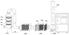
the system comprises a waste crusher 100, a waste feeding and lifting device 200, a waste propelling device 300, a high-temperature heating device 400, a waste anaerobic carbonization device 500, a flue gas conversion, cooling and decompression device 600, a gas conveying pipe 700, a waste gas and tar separation and filtration device 800, an air-suction vacuum pump 900, a water-gas separation device 1000, a circulating water tank 1100, a circulating water purification device 1200, a waste gas water-spraying quartz filtration device 1300, a waste gas biological adsorption, filtration and deodorization device 1400, a waste gas water-spraying nano ceramic filtration device 1500, a multistage activated carbon adsorption and purification device 1600, a spray tower 1700, an activated carbon adsorption and purification box 1800, a UV light oxygen purifier 1900, a centrifugal fan 2000, a purifier discharge device 2100, a complete machine intelligent electric cabinet 2200, a bottom bracket 2300, a feed inlet 2400 and a discharge outlet 2500;
the device comprises a first group of blades 101, a second group of blades 102, a first power 103, a second power 104, a side plate guide structure 105, a unit blade 106, a partition plate 107, a scraper 108, a frame 109, a garbage bin 110, a hopper 111, a guide rail 112, an upper guide wheel 113, a lower guide wheel 114, a sliding plate 115, a sliding block 116, a sliding shaft 117, a limit 118, a steel wire rope 119, an upper guide shaft 120, a lower guide shaft 121, a sliding shaft rotating block 122, a lifting motor 123 and a sliding plate clamp 124; a high temperature resistant pipe 401, an induction heating copper pipe 402, an electric cabinet 403, a cooling water tower 404, an infrared thermometer 405, a water inlet 406, a water outlet 407, a protection pipe 408, a carbon outlet 409 and a capacitor 410; a filtering component 801, a supporting component 802, a tar drainage and collection channel 803, a tar outlet 804 and a tar collection device 805; a first stage filtering and purifying device 1601, a second stage filtering and purifying device 1602, a third stage filtering and purifying device 1603, a filtering device 1604 and a support 1605; an air inlet 1701, a floating ball layer 1702, a spraying device 1703, a viewing port 1704, a water pump 1705, a UV light oxygen layer 1901, a plasma layer 1902 and an electric field layer 1903.
Detailed Description
The present invention will be further explained with reference to the accompanying drawings.
The process flow of the garbage treatment of the harmless household garbage treatment equipment is as follows:
domestic garbage (thrown into a garbage hopper), a belt conveyor (conveying garbage), a cutting and crushing machine (crushing large garbage), a spiral lifting and pushing conveying dryer (garbage feeding), an oxygen-free thermal explosion machine (carbonization and combustion), gas purification and harmless discharge and carbon or organic fertilizer.
Flow description of harmless household garbage treatment equipment:
1, treatment of garbage by a waste crusher 100: the garbage enters the crushing cutter set through the lifting feeding system to crush the garbage;
2, the waste crusher 100 crushes the waste, then drops the crushed waste to a hopper of the waste feeding and lifting device 200, and lifts the crushed waste to a discharge port of the waste feeding and lifting device 200 through spiral conveying;
3, the garbage falls from the discharge port of the garbage feeding and lifting device 200 to the feed hopper of the garbage pushing device 300 and is pushed by a screw to be heated at a high temperature 400;
4, the temperature of the high-temperature heating device 400 can be controlled at 900-1800 ℃ to perform pyrolysis combustion on the propelled garbage;
5, the garbage after pyrolysis and combustion is then pushed into a garbage anaerobic carbonization device 500 to be carbonized, the high-temperature anaerobic retention is carbonized to destroy harmful components of dioxin, and a small amount of carbonized carbon powder is spirally discharged from a discharge hole;
6, the smoke conversion, cooling and pressure reduction device 600 converts smoke of burning garbage into gas in an anoxic state, the gas stays in the tank body for a short time to control flow and discharge so as to reduce discharge of particulate matters, and the cooling water jacket on the surface of the tank body is cooled to reduce discharge of the gas;
7, the gas pipe 700 conveys the gas in the flue gas conversion cooling pressure reduction device 600 to the waste gas tar separation and filtration equipment 800;
8, the waste gas and tar separation and filtration equipment 800 is used for treating gas containing tar and condensed water, the gas transversely penetrates through a filtration material and repeatedly collides with the filter element wall to form brownian motion, the gas is easy to flow out through the filter material due to light weight, and liquid drops such as tar, trace water and the like in the gas flow down into the liquid collecting tank along the filter element wall under the action of gravity, so that tar and water can be separated and filtered; the waste gas tar separation and filtration equipment is used for coarse filtration tar separation, and the following multistage active carbon filtration and purification equipment is used for precise filtration and odor removal;
9, pumping the gas separated and filtered by the waste gas and tar separation and filtration equipment 800 into the water-gas separation device 1000 by the air-pumping vacuum pump 900 through water-gas mixing to adsorb micro-particles in the gas;
10, the water-gas separating device 1000 collides with an inclined wall plate in the device under the pressure of the vacuum pump, gas is upwards transmitted to the next filtering device through a pipeline under the assistance of the pressure due to light weight, and water which adsorbs the gas permeates into sewage purification equipment under the action of gravity and then flows into a circulating water tank 1100 for recycling;
11, the circulating water tank 1100 mainly collects water purified by sewage purification equipment after adsorption spraying;
12, the circulating water purification device 1200 purifies the sewage and the garbage penetrating fluid for equipment water, so that the water energy consumption is reduced;
13, the waste gas water-spraying quartz filtering device 1300 performs water-spraying quartz macadam slow permeation and water-spraying purification on the discharged and filtered waste gas, and is a first round of filtering purification;
14, the biological adsorption, filtration and deodorization device 1400 for waste gas performs a second round of biological adsorption, filtration and deodorization on the gas after the first round of filtration and purification;
15, the waste gas water-spraying nano ceramic filtering device 1500 is used for filtering the gas by the water-spraying of the permeation around the pressure permeation ceramic membrane tube, and the third round of filtering and purification is carried out;
16, the gas of the multistage activated carbon adsorption and purification device 1600 transversely penetrates through the filter material to filter and upwards permeate the activated carbon particle pile for adsorption and purification, and the three-stage circulating filtration and adsorption purification is fourth-wheel filtration and purification;
17, the spray tower 1700 sprays and washes the filtered and purified gas from the front four wheels to ensure that part of the large-particle waste gas is filtered;
18, the filtered gas enters an activated carbon adsorption purification box 1800. The active carbon adsorption method is to utilize active carbon as an adsorbent to adsorb and concentrate harmful substances in gas on the surface of a huge solid phase of the active carbon so as to achieve the aim of purifying waste gas;
19, the UV photo-oxygen purifier 1900 adopts the high-energy high-ozone UV light beam, oxidation reaction catalyst, and high-energy ion generator to degrade the malodorous gas (organic waste gas), and change the malodorous gas such as: ammonia, trimethylamine, hydrogen sulfide, methylthio hydrogen, methyl mercaptan, methyl sulfide, dimethyl disulfide, carbon disulfide and styrene, sulfides H2S, VOCs, molecular chain structures of benzene, toluene and xylene, so that organic or inorganic polymer malodorous compound molecular chains are degraded and converted into low molecular compounds such as CO2, H2O and the like through high-energy ultraviolet light beam irradiation, oxidation reaction of a catalyst and oxidation reaction of positive oxygen ions;
20, the centrifugal fan 2000 discharges the gas which reaches the standard of filtration evolution.
Firstly, the method comprises the following steps: waste crusher 100: comprises a frame 109, a garbage can 110, a hopper 111, a crushing cutter group and a lifting feeding system. The frame 109 is provided with the crushing cutter set and the lifting feeding system, and the crushing cutter set is provided with the hopper 111.
The crushing cutter group has the following structure:
a crushing cutter set comprises a first group of blades 101, a second group of blades 102, a first power 103, a second power 104, a side plate guide structure 105 and a cutter set bracket;
the first group of blades 101 and the second group of blades 102 are arranged in the blade group support, the blade group support is a support with an upper opening and a lower opening and sealed periphery, the first power 103 is connected with the first group of blades 101 to provide rotating power for the first group of blades 101, and the second power 104 is connected with the second group of blades 102 to provide rotating power for the second group of blades 102.
Every a set of blade all sets up a plurality of unit blade 106 and the space bar 107 the same with unit blade number, the space bar is circular panel, and unit blade sets gradually according to the rule of unit blade, space bar, unit blade, space bar with the space bar, and every unit blade includes the plectane of center department and sets up the sword tooth on the plectane, and the plectane and the sword tooth of center department can set up as an organic whole, and every unit blade is equipped with six to sixteen sword teeth, and the number of sword tooth is decided according to the broken particle size of needs, and particle size is big more, and the number of sword teeth is few more.
Hexagonal shafts are arranged at the centers of the unit blades 106 and the partition plates, the first power 103 and the second power 104 drive the first group of blades 101 and the second group of blades 102 to rotate through the hexagonal shafts, and the hexagonal shafts drive the groups of blades to rotate, so that the effect is good, the sliding is avoided, and the center of a circular plate is effectively prevented from being damaged by rapid rotation.
The double-power crushing claw wheels rotate inwards in a staggered mode, the unit blades of the first group of blades correspond to the partition plates of the second group of blades, the partition plates of the first group of blades correspond to the unit blades of the second group of blades, namely the unit blades of the first group of blades 101 and the unit blades of the second group of blades 102 rotate inwards in a staggered mode, and garbage is crushed into small pieces and falls.
The side plate guide 105 is arranged in the knife block holder, and the side plate guide 105 can also be directly used as the knife block holder, which is a simple replacement.
The number of the side plate guide structures is two, the first side plate guide structure is matched with the first group of blades 101, the second side plate guide structure is matched with the second group of blades 102, the side plate guide structures 105 are provided with scraping plates 108 the same as the number of the partition plates of each group of blades, the unit blades can be just contained in the space between the adjacent scraping plates, the scraping plates are arranged corresponding to the partition plates, and the scraping plates are arc-shaped and scrape residual garbage on the partition plates.
The lifting feeding system has the following structure: the device comprises a guide rail 112, a sliding plate 115, a sliding shaft 117, a limit 118, a steel wire rope 119, an upper guide shaft 120, a lower guide shaft 121 and a lifting motor 123;
the bottom of the guide rail 112 is a vertical guide rail, the upper part of the guide rail 112 is a circular arc guide rail, two ends of an upper guide shaft 120 are provided with an upper guide wheel 113 and a sliding shaft rotating block 122, two ends of a lower guide shaft 121 are provided with lower guide wheels 114, the upper guide wheel 113 and the lower guide wheels 114 are arranged in the guide rail 112, the upper guide shaft 120 and the lower guide shaft 121 are connected through a connecting plate 123, the upper guide wheel 113 is lifted along the guide rail 112 to reach an extreme limit position, and the upper guide wheel 113 is propped against by the limit 118; the sliding shaft 117 and the sliding shaft rotating block 122 are welded into a whole, two sliding blocks 116 are installed on each sliding shaft 117, and the sliding plate 115 is installed on four sliding blocks 116. One end of the steel wire rope 119 is controlled by a lifting motor 123, the other end is connected with a sliding plate 115, and a sliding plate clamping position 124 is further arranged on the upper guide shaft 120.
The utility model discloses a waste crusher working process as follows:
1. the sorted garbage is poured into the garbage can 110, at the moment, the sliding plate 115 is positioned at the lowest end of the sliding shaft 117 due to self weight, and when the initial 50MM stroke of lifting is started, the garbage can is hooked;
2. the lifting by 50MM stroke is to clamp the opening edge of the garbage can and the sliding plate 115, so that the garbage can is prevented from being thrown off when the garbage is lifted to pour the garbage;
3. continuing to lift, the slide block 116 reaches the limit position, and the whole slide block assembly of the slide plate begins to lift together;
4. after continuously lifting and turning along the guide rail 112, the upper guide wheel 113 reaches an extreme limit position and is supported by the limit 118;
5. when the steel wire rope 119 is pulled continuously, the slide block assembly is opened by taking the guide shaft 120 as a central fulcrum, so that the garbage can is reversely inclined, and the lifting is stopped until garbage can be completely discharged;
6. when the garbage bin is reversely operated and descends, the garbage bin and the sliding block assembly of the sliding plate are righted firstly due to dead weight, and then the whole movable assembly slides downwards along the guide rail and slowly descends to the initial state;
7. the double-power crushing claw wheels rotate inwards in a staggered mode, so that garbage is crushed into small pieces and falls into a hopper of the spiral feeding mechanism.
The garbage after sorting is poured into the garbage bin, the garbage bin can be hooked when starting of lifting of the sliding plate, the sliding plate and the guide wheel group are lifted along the guide rail groove by the aid of the guide rail and pull rope type lifting system, the sliding plate and the guide wheel group are limited when the upper guide wheel slides to the top end rail, the pull rope continues to be pulled for a certain distance, the process that the sliding plate is reversely inclined is achieved, and when the sliding plate is reversely inclined for a certain angle, the garbage bin can automatically dump garbage.
The double-power crushing claw wheels rotate inwards in a staggered mode, so that garbage is crushed into small pieces and falls into a hopper of the spiral feeding mechanism. The hexagonal shaft drives each group of blades to rotate, the effect is good, sliding is avoided, and meanwhile, the center of the circular plate is effectively prevented from being broken due to rapid rotation.
The garbage carbonization treatment system comprises a high-temperature heating device 400, a garbage anaerobic carbonization device 500 and a flue gas conversion cooling pressure reduction device 600.
The high-temperature heating device 400 comprises a high-temperature resistant pipe 401, an induction heating copper pipe 402, an electric cabinet 403, a cooling water tower 404, an infrared thermometer 405, a rectifier and a capacitor.
The high-temperature resistant pipe 401 is made of high-density tungsten steel, niobium, ceramic alloy materials and other metal pipes through special dies, and is formed through finish machining after compression molding. The inside cavity of induction heating copper pipe 402, cavity department are equipped with mobile water, for its cooling, prevent that the induction heating copper pipe from burning out, and the form of coil is coiled to induction heating copper pipe 402, and the coil is inside to be set up high temperature resistant pipe 401. The high temperature resistant pipe 401 is also hollow, and garbage is pushed into the high temperature resistant pipe by a pusher.
The high temperature heating device 400 adopts the principle of cutting and inducing by an ultra-high power magnetic coil to rapidly heat the high temperature resistant pipe to more than 1200-1800 ℃. The electric cabinet 403 controls the generation of a high-frequency changing magnetic field, the induction heating copper tube 402 in the magnetic field generates heat, and the high-temperature resistant tube 401 generates heat under the action of the induction heating copper tube.
The infrared thermometer 405 is connected with a rectifier and a capacitor, and the measuring range of the infrared thermometer 405 is-25 ℃ to 2000 ℃.
High temperature heating device 400 still includes protection tube 408, protection tube 408 sets up outside induction heating copper pipe, plays fixed protection induction heating copper pipe and thermal-insulated heat preservation effect.
The garbage pushed into the high temperature resistant pipe 401 by the pushing mechanism is subjected to high temperature treatment in the sealed space, and the garbage is combusted to generate carbon and smoke, and flows into the garbage anaerobic carbonization device 500. Dioxin surpasses more than 1000 ℃ in the pipe at high temperature metal pipe, after being pushed rubbish anaerobic carbonization device 500, do the dwell of certain time, rubbish at this moment still is under the high temperature state, can make the dioxin crack like this, be equipped with the intercommunication part between rubbish anaerobic carbonization device 500 and the flue gas conversion cooling pressure relief device 600, this intercommunication part sets up its bore size according to the demand, rational control gas flow prevents to flow too fast, also prevents that the atmospheric pressure in rubbish anaerobic carbonization device 500 is too big.
The garbage pushed into the high-temperature resistant pipe by the material pushing mechanism is subjected to high-temperature treatment in the sealed space, and the garbage is combusted to generate carbon and smoke and flows into the garbage anaerobic carbonization device. Dioxin surpasses more than 1000 ℃ in the pipe at high temperature metal pipe, after pushing rubbish anaerobic carbonization device, does the dwell of certain time, rubbish at this moment still is under the high temperature state, can make the dioxin crack like this, be equipped with the intercommunication part between rubbish anaerobic carbonization device and the flue gas conversion cooling pressure relief device, this intercommunication part sets up its bore size according to the demand, reasonable control gas flow prevents to flow too fast, also prevents that the atmospheric pressure in the rubbish anaerobic carbonization device is too big.
Plasma pyrolysis technology: fundamentally changes the direct combustion (burning) mode of rubbish, realizes carrying out the pyrolysis of oxygen deficiency, abundant carbonization, final carbon residue burn out to rubbish (organic matter), collects the produced low calorific value gas mixture of the pyrolysis of oxygen deficiency through the second stove and burns, waste heat conversion (electricity generation). The technology only realizes simple purification of flue gas emission, but compared with the incineration technology, the technology has higher complexity, great control technology difficulty and reduced heat conversion efficiency, and simultaneously, the matched treatment of the leachate and hazardous wastes cannot be simplified.
Waste gas tar separation filtration equipment 800, it includes waste gas tar separation filtration equipment main part, is equipped with air inlet and gas outlet in the waste gas tar separation filtration equipment main part, and the inside filter part 801 that is equipped with of waste gas tar separation filtration equipment main part, filter part 801 is the upper portion opening, and its bottom is equipped with filtering material with all around, filter part 801 prefers the cylinder shape all around. The filter member 801 is supported by a support member 802 provided in the body of the exhaust gas/tar separation filter device, and the support member 802 is preferably a cross support.
Waste gas tar separation filtration equipment main part is inside and the bottom is equipped with tar drainage and collects ditch 803, tar drainage is collected ditch 803 and is close to the inner wall setting of waste gas tar separation filtration equipment main part, the ditch groove one end of ditch 803 is high, and one end is low, and middle level and smooth decline sets up tar export 804 at the lower extreme, and tar exit linkage tar collection device 805.
The bottom of the waste gas and tar separation and filtration equipment main body is provided with a liquid collecting tank for collecting impurities such as water, dust and the like. And a drain outlet is arranged at the bottom of the liquid collecting tank.
The gas containing tar and condensed water transversely passes through the filtering component 801 and repeatedly collides with the wall of the filter element to form brownian motion, the gas easily penetrates through the filtering material due to light weight, the more the tar and trace water drops in the gas are gathered under the action of gravity, the larger drops are gradually formed and flow down along the wall of the filter element, and the process is the condensation principle. The tar-removing precise filter can not only filter tar, trace water and the like, but also achieve the purpose of separation. Tar flows out from the tar opening along the drainage collecting channel, impurities such as water, dust and the like are gathered in the liquid collecting tank at the bottom of the filter, and the integration of filtering and separation can be achieved by periodically discharging sewage. And the operation is simple and the maintenance is convenient.
The utility model discloses a surround filterable mode all around and filter, save space, the filtration efficiency is high.
Multistage active carbon exhaust filtration purification equipment 1600 uses tertiary active carbon filtration purification equipment as an example here, including first order filtration purification equipment 1601, second level filtration purification equipment 1602, third level filtration purification equipment 1603, and each level filtration purification equipment is equipped with an entry, an export, and the exit linkage second level filtration purification equipment's of first order filtration purification equipment import, the exit linkage third level filtration purification equipment's of second level filtration purification equipment entry.
Inside filter equipment 1604 that is equipped with of each grade filtration clarification plant, filter equipment 1604 are upper portion open-ended filter, and its bottom is equipped with filtering material with all around, filter equipment 1604 is supported by the support frame 1605 that sets up in each grade filtration clarification plant. For example, the support 1605 is a cross support. The periphery of the filter 1604 is preferably cylindrical. The filtering precision is increased from the first stage filtering and purifying equipment to the third stage filtering and purifying equipment in sequence, namely the filtering precision of the third stage filtering and purifying equipment is the finest. For tertiary active carbon filtration purification equipment, can preferably be that first order filtration purification equipment is active carbon filter equipment, mainly go out the peculiar smell, the main particulate matter of discharging of drain, second level filtration purification equipment's drain is main dust and active carbon granule of discharging, third level filtration purification equipment's drain is main drainage water and oil. The outlet of the first stage of filtering and purifying equipment is as high as the inlet of the second stage of filtering and purifying equipment, and the outlet of the second stage of filtering and purifying equipment is as high as the inlet of the third stage of filtering and purifying equipment.
The bottom of each stage of filtering and purifying equipment is a liquid collecting tank, the bottom of the liquid collecting tank is provided with a drain outlet, and the drain outlet is provided with a control valve for controlling the opening or closing of the drain outlet.
The special peculiar smell gas containing tar and condensed water transversely passes through the primary active carbon filter material, the gas easily penetrates through the filter material, the peculiar smell in the gas is filtered out by the active carbon filter material, the gas without the peculiar smell transversely passes through the secondary coarse filter device and repeatedly collides with the wall of the filter element to form Brownian motion, the gas easily penetrates through the filter material due to light weight, and the dust and the active carbon particles in the gas are more and more gathered under the action of gravity to gradually form larger impurities. The gas after secondary filtration transversely passes through the three-stage fine filtering device and repeatedly collides with the filter element wall to form brownian motion, and the gas easily penetrates through the filter material due to light weight, and water and oil in the gas are more and more gathered under the action of gravity to gradually form larger liquid drops. Flows down along the filter element wall, and the process is the coalescence principle. The tar-removing precise filter can not only filter tar, trace water and the like, but also achieve the purpose of separation. The filter is gathered in a liquid collecting tank at the bottom of the filter, and the integration of filtration and separation can be achieved by periodically discharging sewage. And the operation is simple and the maintenance is convenient.
The utility model discloses a surround filterable mode all around and filter, save space, the filtration efficiency is high.
The spray tower is also called a water spray exhaust gas purification tower and comprises an air suction opening 1701, a suspension ball layer 1702, a spray device 1703, an observation opening 1704 and a water pump 1705. The main body of the spray tower 1700 is made of corrosion-resistant PP (polypropylene) plates or glass materials, the observation port 1704 is arranged on the main body of the spray tower, and a plurality of observation ports can be arranged. The suspension ball layer 1702 and the spraying device 1703 are arranged in the main body of the spray tower, the spraying device 1703 is arranged at the upper part of the corresponding suspension ball layer 1702, the suspension ball layer 1702 is preferably provided with two layers or three layers, the spraying device 1703 is preferably provided with two layers or three layers, one layer of spraying device is provided with a plurality of spraying ports, and each layer of spraying device corresponds to one layer or a plurality of layers of suspension ball layers. The spray device 1703 is connected to a water pump 1705.
The gas is sucked into the suction inlet 1701 by the centrifugal fan, flows upward to the floating ball layer 1702, and contacts and reacts with the spray liquid sprayed from the spray device 1703. According to various indexes such as gas purification conditions, a multi-stage suspension ball layer and a spraying device can be additionally arranged, and the gas after being purified is treated and discharged to the activated carbon adsorption purification box 1800 through a demister.
The suspension ball layer is provided with a plurality of small balls with lighter weight, the small balls roll under the action of the spraying liquid, and the retention time of gas in the suspension ball layer is prolonged, so that the spraying time is prolonged, the spraying effect is better, and the gas purifying time is longer. The spray tower has the advantages of high effective force, strong corrosion resistance, high strength, low noise, power saving, small volume, convenient disassembly, assembly and maintenance, lightness, durability and the like.
The spray tower equipment is characterized in that the equipment adopts the suspension ball layer to purify the waste gas, and is suitable for the treatment of continuously and intermittently discharged waste gas; the process is simple, the management, the operation and the maintenance are quite convenient and simple, and no influence is caused on the production of a workshop; the application range is wide, and various pollutants can be purified simultaneously; the pressure drop is low, the operation elasticity is high, and the demisting performance is good; the tower body can be made of FRP/PP/PVC and other materials according to actual conditions; the suspension ball layer adopts a high-efficiency and low-resistance pall ring, and can thoroughly remove peculiar smell, harmful substances and the like in the gas.
The application range is as follows: spray tower application: the process and the equipment can be widely applied to the purification treatment of acid and alkaline waste gas discharged in the processes of chemical industry, electronics, metallurgy, electroplating, textile (chemical fiber), food, mechanical manufacturing and other industries. Such as flavoring food, pickling, electroplating, electrolysis, accumulator, etc.
After the waste gas generated in the production process of the equipment is washed by the spray tower, a part of large-particle waste gas is filtered, and the rest clean tail gas is filtered by the mesh filter and then enters the activated carbon adsorption purification box 1800. The activated carbon adsorption method is a method for purifying waste gas by using activated carbon as an adsorbent and carrying out adsorption concentration on harmful substances in gas on the surface of a huge solid phase of the activated carbon. It possesses the advantages of high treatment efficiency and less investment, etc., and is specially applicable to intermittent small-batch production. The active carbon adsorbs purifying box branch wind section, active carbon filter segment and air-out section, and organic waste gas gets into the box from the air intake, and tail gas up to standard after the purification is arranged to the atmosphere under the ventilation blower suction.
First filtering: the V-shaped paper dry filter (fire-proof type) removes large particle impurities in the exhaust gas and moisture in the exhaust gas.
The V-shaped filter paper has the characteristics that: paint filter paper adopts imported swiss kraft paper, and the structure of fold effectively absorbs the overspray of super scope, forces the filtration air current to change the direction flow many times, and the coating cloud granule in the air adheres on filter paper, can not take away along with the air current, and fire prevention V type paper filter adopts fire prevention paper filtering material, and paint adsorption efficiency is strong, good continuous air current stability, and the air current is unobstructed to guarantee better spraying condition and better surface quality control, the spraying quality is higher. The operation cost is low, the service life is longer, the operation is easy, the installation is convenient, and the environment-friendly recovery can be realized.
Second activated carbon and third: the air is powered by a fan, and enters the box body under positive pressure or negative pressure, unbalanced and unsaturated molecular attraction or chemical bond force exists on the surface of the activated carbon solid, so that when the surface of the activated carbon solid is contacted with the air, the molecules of the air can be attracted, concentrated and kept on the surface of the solid, pollutants are adsorbed, and waste gas enters an equipment dust exhaust system after passing through a filter, so that purified gas is discharged at high altitude up to the standard.
The discharged gas enters a UV light oxygen purifier 1900, and the UV light oxygen purifier 1900 is provided with a UV light oxygen layer 1901, a plasma layer 1902, and an electric field layer 1903 in this order. UV: ultraviolet rays.
The device further comprises a purifier discharging device 2100 and a sampling monitoring device, wherein the purifier discharging device 2100 is connected with an outlet of the UV light oxygen purifier 1900, and the purified gas is discharged by the centrifugal fan 2000. The sampling monitoring device is connected with the outlet of the UV light oxygen purifier 1900 or the centrifugal fan 2000.
The utility model discloses a design scale and waste gas peculiar smell standard of exhaust-gas treatment system
GB16297-1996 New pollution Source atmospheric pollution Source emission Limit

1. Odor purification rate: more than or equal to 95 percent;
2. organic waste gas purification rate: more than or equal to 95 percent;
3. the chimney discharge height: 15m above the ground;
4. purification apparatus system resistance: less than or equal to 300 Pa;
feasibility for treating waste gas in scheme
(1) The method is environment-friendly and pollution-free, and simultaneously has advanced process and high purification efficiency.
(2) The automatic, continuous and stable operation of the purification equipment is realized; and the system parameters are convenient to adjust. And can be used for manual operation to facilitate debugging and maintenance of the equipment.
The scheme has the advantage of treating waste gas
(1) Applicability: the technology adopted by the project is suitable for the scale of waste gas treatment required by the owner, the waste gas pollutants required to be removed, the regional characteristics and the management level. The expression is as follows:
the adopted technology is suitable for removing pollutants;
the adopted technology is suitable for the required equipment, and comprises main equipment and auxiliary equipment;
the adopted technology is suitable for the characteristics of the area where the project is located, the quality of the staff and the management level;
the adopted technology is suitable for the capacity of treating pollutant emission waste gas.
(2) Reliability: the waste gas treatment process is mature and reliable, can ensure the treatment effect, performance and treatment capacity, and avoids resource waste, secondary pollution and safety hazard.
(3) The economic efficiency is as follows: the project fully considers the one-time investment cost and the operation cost which can happen in the future.
(4) Safety: fully considers the safety factors of fire control, explosion prevention and the like, and has stable operation, safety and reliability.
Therefore, by combining the factors, the purification system of the scheme has relative advantages in the aspects of technical rationality, advancement and economic feasibility. The construction cost and the operation cost are relatively reasonable, the adopted technical principle is reasonable and feasible, and the project is safe to implement.
The foregoing is a more detailed description of the present invention, taken in conjunction with the specific preferred embodiments thereof, and it is not intended that the invention be limited to the specific embodiments shown and described. To the utility model belongs to the technical field of ordinary technical personnel, do not deviate from the utility model discloses under the prerequisite of design, can also make a plurality of simple deductions or replacement, all should regard as belonging to the utility model discloses a protection scope.
Claims (4)
1. The utility model provides a waste gas tar separation filtration equipment which characterized in that: which comprises a main body of the waste gas and tar separation and filtration equipment, wherein the main body of the waste gas and tar separation and filtration equipment is provided with an air inlet and an air outlet, a filtration part (801) is arranged inside the main body of the waste gas and tar separation and filtration equipment, the filtration part (801) is provided with an opening at the upper part, the bottom and the periphery of the device are provided with filtering materials, the filtering part (801) is supported by a supporting part (802) arranged in the waste gas and tar separation and filtration device main body, a tar drainage and collection channel (803) is arranged in the waste gas and tar separation and filtration device main body and at the bottom, the tar drainage and collection channel (803) is arranged close to the inner wall of the main body of the waste gas and tar separation and filtration equipment, one end of the groove of the tar drainage and collection groove (803) is high, the other end is low, the middle part is smoothly descended, the lowest part is provided with a tar outlet (804), the bottom of the waste gas and tar separation and filtration equipment main body is a liquid collecting tank, and the bottom of the liquid collecting tank is provided with a sewage outlet.
2. The exhaust gas tar separating and filtering apparatus according to claim 1, characterized in that: the supporting component (802) is a cross-shaped supporting frame.
3. The exhaust gas tar separating and filtering apparatus according to claim 1, characterized in that: the periphery of the filter component (801) is cylindrical.
4. The exhaust gas tar separating and filtering apparatus according to claim 1, characterized in that: the tar outlet is connected with a tar collecting device (805).
Priority Applications (1)
| Application Number | Priority Date | Filing Date | Title |
|---|---|---|---|
| CN201921044227.0U CN210845578U (en) | 2019-07-05 | 2019-07-05 | Waste gas tar separation and filtration equipment |
Applications Claiming Priority (1)
| Application Number | Priority Date | Filing Date | Title |
|---|---|---|---|
| CN201921044227.0U CN210845578U (en) | 2019-07-05 | 2019-07-05 | Waste gas tar separation and filtration equipment |
Publications (1)
| Publication Number | Publication Date |
|---|---|
| CN210845578U true CN210845578U (en) | 2020-06-26 |
Family
ID=71300043
Family Applications (1)
| Application Number | Title | Priority Date | Filing Date |
|---|---|---|---|
| CN201921044227.0U Expired - Fee Related CN210845578U (en) | 2019-07-05 | 2019-07-05 | Waste gas tar separation and filtration equipment |
Country Status (1)
| Country | Link |
|---|---|
| CN (1) | CN210845578U (en) |
Cited By (1)
| Publication number | Priority date | Publication date | Assignee | Title |
|---|---|---|---|---|
| CN111939664A (en) * | 2020-08-31 | 2020-11-17 | 成都喃呓商贸有限公司 | Flue gas purification equipment for rubber processing |
-
2019
- 2019-07-05 CN CN201921044227.0U patent/CN210845578U/en not_active Expired - Fee Related
Cited By (1)
| Publication number | Priority date | Publication date | Assignee | Title |
|---|---|---|---|---|
| CN111939664A (en) * | 2020-08-31 | 2020-11-17 | 成都喃呓商贸有限公司 | Flue gas purification equipment for rubber processing |
Similar Documents
| Publication | Publication Date | Title |
|---|---|---|
| CN110479731B (en) | Harmless household garbage treatment equipment | |
| CN210907353U (en) | Harmless household garbage treatment equipment | |
| US4157961A (en) | Combined waste water clarification and trash disposal system | |
| CN101786094B (en) | Combined treatment process for household garbage and sewage | |
| CN208406422U (en) | A kind of spray paint dust-removing waste gas purification integrated machine | |
| CN208151175U (en) | A kind of oily sludge harmless treatment device | |
| CN110354603A (en) | A kind of spray paint dust-removing waste gas purification integrated machine | |
| CN100571842C (en) | A kind of improvement method and device of fish powder waste gases | |
| CN210711398U (en) | Garbage carbonization treatment system | |
| CN210845784U (en) | Multistage active carbon waste gas filtering and purifying equipment | |
| CN104984626A (en) | Wood charcoal kiln smoke gas treatment system | |
| CN210846641U (en) | Waste crushing cutter set | |
| CN112097263A (en) | Mixed household garbage sorting harmless treatment system | |
| CN110257090A (en) | Division solves garbage carbonized processing system | |
| CN110551550A (en) | RDF prepared from household garbage and high-temperature pyrolysis gasification treatment process | |
| CN214914670U (en) | Dry tail gas washing of wood-based plate and wet electric coupling purifier | |
| CN210906438U (en) | Waste crusher | |
| CN211726167U (en) | Coal tar hydrogenation tar sediment cooling VOCs gas cleaning device | |
| CN210907352U (en) | Mobile harmless household garbage treatment equipment | |
| CN210905525U (en) | Light oxygen plasma exhaust treatment system | |
| CN217398673U (en) | Gas station phenol water deoiling evaporation treatment integrated equipment | |
| CN112222171B (en) | Three-phase separation device, and thermal desorption treatment process and system for volatile contaminated soil | |
| CN212792348U (en) | A gas cleaning device for pitch mix station | |
| CN114409169A (en) | Gas station phenol water oil removal evaporation treatment device and process | |
| CN205245205U (en) | Novel garbage incinerator |
Legal Events
| Date | Code | Title | Description |
|---|---|---|---|
| GR01 | Patent grant | ||
| GR01 | Patent grant | ||
| CF01 | Termination of patent right due to non-payment of annual fee | ||
| CF01 | Termination of patent right due to non-payment of annual fee |
Granted publication date: 20200626 |