CN210838633U - An electrical cabinet for intelligent cooling buildings - Google Patents
An electrical cabinet for intelligent cooling buildings Download PDFInfo
- Publication number
- CN210838633U CN210838633U CN201921819802.XU CN201921819802U CN210838633U CN 210838633 U CN210838633 U CN 210838633U CN 201921819802 U CN201921819802 U CN 201921819802U CN 210838633 U CN210838633 U CN 210838633U
- Authority
- CN
- China
- Prior art keywords
- fixedly connected
- shell
- heat dissipation
- pipe
- water pump
- Prior art date
- Legal status (The legal status is an assumption and is not a legal conclusion. Google has not performed a legal analysis and makes no representation as to the accuracy of the status listed.)
- Expired - Fee Related
Links
- 238000001816 cooling Methods 0.000 title claims abstract description 25
- XLYOFNOQVPJJNP-UHFFFAOYSA-N water Substances O XLYOFNOQVPJJNP-UHFFFAOYSA-N 0.000 claims abstract description 31
- 239000007788 liquid Substances 0.000 claims abstract description 24
- 230000017525 heat dissipation Effects 0.000 claims abstract description 23
- 239000000110 cooling liquid Substances 0.000 claims description 24
- 238000005192 partition Methods 0.000 claims description 10
- 238000009423 ventilation Methods 0.000 claims description 10
- 230000005611 electricity Effects 0.000 claims 5
- 210000000056 organ Anatomy 0.000 claims 2
- 239000002826 coolant Substances 0.000 abstract description 18
- 230000007774 longterm Effects 0.000 description 5
- 239000010865 sewage Substances 0.000 description 4
- 229910000831 Steel Inorganic materials 0.000 description 3
- 230000002159 abnormal effect Effects 0.000 description 3
- 238000010276 construction Methods 0.000 description 3
- 239000000428 dust Substances 0.000 description 3
- 239000010959 steel Substances 0.000 description 3
- 239000010960 cold rolled steel Substances 0.000 description 2
- 238000010586 diagram Methods 0.000 description 2
- 238000000034 method Methods 0.000 description 2
- 238000012986 modification Methods 0.000 description 2
- 230000004048 modification Effects 0.000 description 2
- 239000002699 waste material Substances 0.000 description 2
- 230000009286 beneficial effect Effects 0.000 description 1
- 238000004891 communication Methods 0.000 description 1
- 230000007613 environmental effect Effects 0.000 description 1
- 238000002474 experimental method Methods 0.000 description 1
- 238000004519 manufacturing process Methods 0.000 description 1
- 238000012544 monitoring process Methods 0.000 description 1
- 239000000126 substance Substances 0.000 description 1
Images


Landscapes
- Cooling Or The Like Of Electrical Apparatus (AREA)
Abstract
Description
技术领域technical field
本实用新型涉及建筑电气柜技术领域,具体为一种智能散热建筑用电气柜。The utility model relates to the technical field of building electrical cabinets, in particular to an intelligent heat dissipation building electrical cabinet.
背景技术Background technique
电气柜是由钢材质加工而成用来保护元器件正常工作的柜子,电气柜制作材料一般分为热轧钢板和冷轧钢板两种,冷轧钢板相对热轧钢板更材质柔软,更适合电气柜的制作,电气柜用途广泛,主要用于化工行业、环保行业、电力系统、冶金系统、核电行业、消防安全监控和交通行业等,在建筑的过程中需要用到电力柜对电力进行传输和控制,但是现有的建筑用电气柜不能对电气框内部进行智能散热降温的功能,长时间运行导致电气柜内部的温度过高,损害电气柜内部的电气元件,造成严重的损失,从而降低了电气元件的使用寿命。Electrical cabinets are made of steel to protect components from working properly. Electrical cabinets are generally made of hot-rolled steel and cold-rolled steel. Cold-rolled steel is softer than hot-rolled steel and more suitable for electrical appliances. The production of cabinets, electrical cabinets are widely used, mainly used in chemical industry, environmental protection industry, power system, metallurgical system, nuclear power industry, fire safety monitoring and transportation industry, etc. In the process of construction, power cabinets need to be used to transmit and However, the existing building electrical cabinets cannot intelligently dissipate heat and cool the inside of the electrical frame. Long-term operation will lead to excessive temperature inside the electrical cabinet, damage the electrical components inside the electrical cabinet, and cause serious losses, thereby reducing the Service life of electrical components.
实用新型内容Utility model content
本实用新型的目的在于提供一种智能散热建筑用电气柜,具备对电气框内部进行智能散热降温的优点,解决了现有的建筑用电气柜不能对电气框内部进行智能散热降温的功能,长时间运行导致电气柜内部的温度过高,损害电气柜内部的电气元件,造成严重的损失,从而降低了电气元件使用寿命的问题。The purpose of the utility model is to provide an intelligent heat dissipation building electrical cabinet, which has the advantages of intelligently cooling the inside of the electrical frame, and solves the problem that the existing building electrical cabinet cannot perform intelligent heat dissipation and cooling inside the electrical frame. Time running causes the temperature inside the electrical cabinet to be too high, damages the electrical components inside the electrical cabinet, and causes serious losses, thereby reducing the service life of the electrical components.
为实现上述目的,本实用新型提供如下技术方案:一种智能散热建筑用电气柜,包括壳体,所述壳体的顶部通过支架固定连接有遮雨板,所述壳体的左侧固定连接有冷却液箱,所述冷却液箱顶部的左侧固定连通有加液管,所述壳体左侧的顶部通过支架固定连接有水泵,所述水泵进水管的底部贯穿至冷却液箱的内腔并固定连通有输送管,所述水泵出水管的一端贯穿至冷却液箱的内腔并固定连通有冷却弯管,所述冷却弯管远离水泵的一端贯穿至壳体的外部并与冷却液箱的底部固定连通,所述壳体的顶部固定连通有排气管,所述排气管的内腔通过支架固定连接与电机,所述电机转轴的两侧均固定连接有扇叶,所述壳体的内壁固定连接有分隔板,所述分隔板的顶部开设有通孔,所述壳体右侧的底部开设有通风孔,所述壳体内腔顶部的左侧固定连接有温度传感器,所述壳体内腔顶部的右侧由左至右分别固定连接有处理器和无线收发器,所述壳体的右侧通过支架固定连接有太阳能电池板,所述壳体右侧的底部固定连接有框体,所述框体内腔的底部放置有蓄电池,所述壳体的正面通过铰链活动连接有箱门;In order to achieve the above purpose, the present invention provides the following technical solutions: an electrical cabinet for intelligent heat dissipation buildings, comprising a shell, the top of the shell is fixedly connected with a rain shield through a bracket, and the left side of the shell is fixedly connected There is a cooling liquid tank, the left side of the top of the cooling liquid tank is fixedly connected with a liquid filling pipe, the top of the left side of the shell is fixedly connected with a water pump through a bracket, and the bottom of the water pump water inlet pipe penetrates into the cooling liquid tank. The cavity is fixed and communicated with a conveying pipe. One end of the water pump outlet pipe penetrates into the inner cavity of the cooling liquid tank and is fixedly connected with a cooling elbow. The bottom of the box is fixedly connected, the top of the casing is fixedly connected with an exhaust pipe, the inner cavity of the exhaust pipe is fixedly connected to the motor through a bracket, and both sides of the motor shaft are fixedly connected with fan blades. The inner wall of the casing is fixedly connected with a dividing plate, the top of the dividing plate is provided with a through hole, the bottom of the right side of the casing is provided with a ventilation hole, and the left side of the top of the inner cavity of the casing is fixedly connected with a temperature sensor , the right side of the top of the inner cavity of the casing is fixedly connected with a processor and a wireless transceiver from left to right, the right side of the casing is fixedly connected with a solar panel through a bracket, and the bottom of the right side of the casing is fixed A frame is connected, a battery is placed at the bottom of the inner cavity of the frame, and a box door is movably connected to the front of the casing through a hinge;
所述处理器与无线收发器双向电连接,所述蓄电池的输出端与处理器的输入端电连接,所述太阳能电池板的输出端与蓄电池的输入端电连接,所述处理器的输出端分别与水泵和电机的输入端电连接,所述温度传感器的输出端与处理器的输入端电连接,所述处理器的输出端电连接有报警模块。The processor and the wireless transceiver are electrically connected bidirectionally, the output end of the battery is electrically connected to the input end of the processor, the output end of the solar panel is electrically connected to the input end of the battery, and the output end of the processor is electrically connected The temperature sensor is electrically connected to the input ends of the water pump and the motor respectively, the output end of the temperature sensor is electrically connected to the input end of the processor, and the output end of the processor is electrically connected to an alarm module.
优选的,所述箱门正面的右侧固定连接有把手,所述箱门正面的底部开设有散热孔。Preferably, a handle is fixedly connected to the right side of the front side of the box door, and a heat dissipation hole is opened at the bottom of the front side of the box door.
优选的,所述报警模块包括报警灯和蜂鸣器,所述报警灯固定安装于壳体顶部的左侧,所述蜂鸣器固定安装于壳体顶部的右侧。Preferably, the alarm module includes an alarm lamp and a buzzer, the alarm lamp is fixedly installed on the left side of the top of the casing, and the buzzer is fixedly installed on the right side of the top of the casing.
优选的,所述冷却液箱的正面固定连接有液位窗,液位窗的正面喷涂有刻度线。Preferably, a liquid level window is fixedly connected to the front of the cooling liquid tank, and a scale line is sprayed on the front of the liquid level window.
优选的,所述冷却液箱左侧的底部固定连通有排污管,排污管的表面设置有阀门。Preferably, a sewage pipe is fixedly connected to the bottom of the left side of the cooling liquid tank, and a valve is provided on the surface of the sewage pipe.
优选的,所述排气管的顶部螺纹套设有网罩,所述框体的正面通过活动连接有盖板。Preferably, the top thread of the exhaust pipe is sleeved with a mesh cover, and the front surface of the frame body is movably connected with a cover plate.
优选的,所述通风孔的内壁固定连接有滤网,滤网的形状为圆形。Preferably, a filter screen is fixedly connected to the inner wall of the ventilation hole, and the shape of the filter screen is circular.
与现有技术相比,本实用新型的有益效果如下:Compared with the prior art, the beneficial effects of the present utility model are as follows:
1、本实用新型通过壳体、遮雨板、冷却液箱、加液管、水泵、输送管、冷却弯管、排气管、电机、扇叶、分隔板、通孔、通风孔、温度传感器、处理器、无线收发器、太阳能电池板、框体、蓄电池和箱门进行配合,具备对电气框内部进行智能散热降温的优点,解决了现有的建筑用电气柜不能对电气框内部进行智能散热降温的功能,长时间运行导致电气柜内部的温度过高,损害电气柜内部的电气元件,造成严重的损失,从而降低了电气元件使用寿命的问题。1. The utility model passes through the shell, the rain shield, the cooling liquid tank, the liquid filling pipe, the water pump, the conveying pipe, the cooling elbow, the exhaust pipe, the motor, the fan blade, the partition plate, the through hole, the ventilation hole, the temperature The combination of sensors, processors, wireless transceivers, solar panels, frames, batteries and box doors has the advantage of intelligently cooling and cooling the inside of the electrical frame, which solves the problem that the existing building electrical cabinets cannot be used for the inside of the electrical frame. The function of intelligent heat dissipation and cooling, long-term operation leads to excessive temperature inside the electrical cabinet, damages the electrical components inside the electrical cabinet, and causes serious losses, thereby reducing the service life of electrical components.
2、本实用新型通过设置散热孔,对壳体内进行通风散热,通过设置报警灯和蜂鸣器,对过往的路人进行提醒,告知此处存在危险,并提醒工作人员对异常情况进行检查,通过设置液位窗和刻度线,方便观察冷却液箱内的冷却液位置,并通过加液管及时往冷却液箱内注入冷却液,通过设置排污管和阀门,将冷却液箱内长时间使用后的变质冷却液进行排出更换,通过设置网罩,防止灰尘和建筑垃圾进入到壳体内,通过设置滤网,防止灰尘和垃圾进入到壳体内。2. The utility model ventilates and dissipates heat in the casing by setting heat dissipation holes, and reminds passers-by by setting up alarm lights and buzzers, and informs that there is danger here, and reminds the staff to check the abnormal situation, and pass the warning light and buzzer. Set the liquid level window and scale line to facilitate the observation of the coolant position in the coolant tank, and inject the coolant into the coolant tank in time through the liquid filling pipe. The deteriorated coolant is discharged and replaced. By setting the mesh cover, dust and construction waste are prevented from entering the casing, and the filter screen is set to prevent dust and garbage from entering the casing.
附图说明Description of drawings
图1为本实用新型结构示意图;Fig. 1 is the structural representation of the utility model;
图2为本实用新型正视结构示意图;Fig. 2 is the front view structure schematic diagram of the utility model;
图3为本实用新型分隔板和壳体连接俯视示意图;Fig. 3 is a schematic top view of the connection between the partition plate and the casing of the present invention;
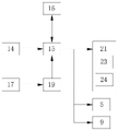
图4为本实用新型系统原理图。FIG. 4 is a schematic diagram of the system of the present invention.
图中:1壳体、2遮雨板、3冷却液箱、4加液管、5水泵、6输送管、7冷却弯管、8排气管、9电机、10扇叶、11分隔板、12通孔、13通风孔、14温度传感器、15处理器、16无线收发器、17太阳能电池板、18框体、19蓄电池、20箱门、21报警模块、22散热孔、23报警灯、24蜂鸣器。In the picture: 1 shell, 2 weather shield, 3 coolant tank, 4 liquid filling pipe, 5 water pump, 6 conveying pipe, 7 cooling elbow, 8 exhaust pipe, 9 motor, 10 fan blade, 11 partition plate , 12 through holes, 13 ventilation holes, 14 temperature sensors, 15 processors, 16 wireless transceivers, 17 solar panels, 18 frames, 19 batteries, 20 doors, 21 alarm modules, 22 cooling holes, 23 alarm lights, 24 buzzers.
具体实施方式Detailed ways
下面将结合本实用新型实施例中的附图,对本实用新型实施例中的技术方案进行清楚、完整地描述,显然,所描述的实施例仅仅是本实用新型一部分实施例,而不是全部的实施例。基于本实用新型中的实施例,本领域普通技术人员在没有做出创造性劳动前提下所获得的所有其他实施例,都属于本实用新型保护的范围。The technical solutions in the embodiments of the present utility model will be clearly and completely described below with reference to the accompanying drawings in the embodiments of the present utility model. Obviously, the described embodiments are only a part of the embodiments of the present utility model, rather than all the implementations. example. Based on the embodiments of the present invention, all other embodiments obtained by those of ordinary skill in the art without creative work fall within the protection scope of the present invention.
在实用新型的描述中,需要说明的是,术语“上”、“下”、“内”、“外”“前端”、“后端”、“两端”、“一端”、“另一端”等指示的方位或位置关系为基于附图所示的方位或位置关系,仅是为了便于描述本实用新型和简化描述,而不是指示或暗示所指的装置或元件必须具有特定的方位、以特定的方位构造和操作,因此不能理解为对本实用新型的限制。此外,术语“第一”、“第二”仅用于描述目的,而不能理解为指示或暗示相对重要性。In the description of the utility model, it should be noted that the terms "upper", "lower", "inner", "outer", "front end", "rear end", "two ends", "one end" and "the other end" The orientation or positional relationship indicated by etc. is based on the orientation or positional relationship shown in the accompanying drawings, which is only for the convenience of describing the present invention and simplifying the description, rather than indicating or implying that the referred device or element must have a specific orientation, with a specific orientation. Therefore, it should not be construed as a limitation on the present invention. Furthermore, the terms "first" and "second" are used for descriptive purposes only and should not be construed to indicate or imply relative importance.
在实用新型的描述中,需要说明的是,除非另有明确的规定和限定,术语“安装”、“设置有”、“连接”等,应做广义理解,例如“连接”,可以是固定连接,也可以是可拆卸连接,或一体地连接;可以是机械连接,也可以是电连接;可以是直接相连,也可以通过中间媒介间接相连,可以是两个元件内部的连通。对于本领域的普通技术人员而言,可以具体情况理解上述术语在本实用新型中的具体含义。In the description of the utility model, it should be noted that, unless otherwise expressly specified and limited, the terms "installed", "provided with", "connected", etc., should be understood in a broad sense, for example, "connected" may be a fixed connection It can also be a detachable connection or an integral connection; it can be a mechanical connection or an electrical connection; it can be a direct connection, or an indirect connection through an intermediate medium, or the internal communication between the two components. For those of ordinary skill in the art, the specific meanings of the above terms in the present invention can be understood in specific situations.
本实用新型的壳体1、遮雨板2、冷却液箱3、加液管4、水泵5、输送管6、冷却弯管7、排气管8、电机9、扇叶10、分隔板11、通孔12、通风孔13、温度传感器14、处理器15、无线收发器16、太阳能电池板17、框体18、蓄电池19、箱门20、报警模块21、散热孔22、报警灯23和蜂鸣器24部件均为通用标准件或本领域技术人员知晓的部件,其结构和原理都为本技术人员均可通过技术手册得知或通过常规实验方法获知。The utility model has a
请参阅图1-4,一种智能散热建筑用电气柜,包括壳体1,壳体1的顶部通过支架固定连接有遮雨板2,壳体1的左侧固定连接有冷却液箱3,冷却液箱3顶部的左侧固定连通有加液管4,壳体1左侧的顶部通过支架固定连接有水泵5,水泵5进水管的底部贯穿至冷却液箱3的内腔并固定连通有输送管6,水泵5出水管的一端贯穿至冷却液箱3的内腔并固定连通有冷却弯管7,冷却弯管7远离水泵5的一端贯穿至壳体1的外部并与冷却液箱3的底部固定连通,壳体1的顶部固定连通有排气管8,排气管8的内腔通过支架固定连接与电机9,电机9转轴的两侧均固定连接有扇叶10,壳体1的内壁固定连接有分隔板11,分隔板11的顶部开设有通孔12,壳体1右侧的底部开设有通风孔13,壳体1内腔顶部的左侧固定连接有温度传感器14,壳体1内腔顶部的右侧由左至右分别固定连接有处理器15和无线收发器16,壳体1的右侧通过支架固定连接有太阳能电池板17,壳体1右侧的底部固定连接有框体18,框体18内腔的底部放置有蓄电池19,壳体1的正面通过铰链活动连接有箱门20;Please refer to Figure 1-4, an electrical cabinet for intelligent heat dissipation building, including a
处理器15与无线收发器16双向电连接,蓄电池19的输出端与处理器15的输入端电连接,太阳能电池板17的输出端与蓄电池19的输入端电连接,处理器15的输出端分别与水泵5和电机9的输入端电连接,温度传感器14的输出端与处理器15的输入端电连接,处理器15的输出端电连接有报警模块21,箱门20正面的右侧固定连接有把手,箱门20正面的底部开设有散热孔22,通过设置散热孔22,对壳体1内进行通风散热,报警模块21包括报警灯23和蜂鸣器24,报警灯23固定安装于壳体1顶部的左侧,蜂鸣器24固定安装于壳体1顶部的右侧,通过设置报警灯23和蜂鸣器24,对过往的路人进行提醒,告知此处存在危险,并提醒工作人员对异常情况进行检查,冷却液箱3的正面固定连接有液位窗,液位窗的正面喷涂有刻度线,通过设置液位窗和刻度线,方便观察冷却液箱3内的冷却液位置,并通过加液管4及时往冷却液箱3内注入冷却液,冷却液箱3左侧的底部固定连通有排污管,排污管的表面设置有阀门,通过设置排污管和阀门,将冷却液箱3内长时间使用后的变质冷却液进行排出更换,排气管8的顶部螺纹套设有网罩,框体18的正面通过活动连接有盖板,通过设置网罩,防止灰尘和建筑垃圾进入到壳体1内,通风孔13的内壁固定连接有滤网,滤网的形状为圆形,通过设置滤网,防止灰尘和垃圾进入到壳体1内,通过壳体1、遮雨板2、冷却液箱3、加液管4、水泵5、输送管6、冷却弯管7、排气管8、电机9、扇叶10、分隔板11、通孔12、通风孔13、温度传感器14、处理器15、无线收发器16、太阳能电池板17、框体18、蓄电池19和箱门20进行配合,具备对电气框内部进行智能散热降温的优点,解决了现有的建筑用电气柜不能对电气框内部进行智能散热降温的功能,长时间运行导致电气柜内部的温度过高,损害电气柜内部的电气元件,造成严重的损失,从而降低了电气元件使用寿命的问题。The
使用时,当温度传感器14检测到壳体1内的温度达到设置的温度范围内时,温度传感器14将信息反馈给处理器15,处理器15控制水泵5和电机9的运行,水泵5的运行将冷却液箱3内的冷却液依次通过输送管6、水泵5和冷却弯管7和回流到冷却液箱3的内腔进行循环,当冷却液通过冷却弯管7时对壳体1的内腔进行降温,电机9转轴的转动带动扇叶10的转动将壳体1内腔的热空气通过排气管8排出,从而对整个壳体1的内腔进行智能散热降温,直至降低到设置的温度范围外,当对壳体1内腔进行降温时,温度传感器14检测到壳体1内的温度还在继续上升并且超出设置的最高温度范围外时,温度传感器14将信息反馈给处理器15,处理器15会先控制无线收发器16将信息无线传送至监控中心的计算机上,来提醒工作人员,并通知工作人员对异常情况进行检查,同时处理器15控制蜂鸣器24发出声音报警,控制报警灯23闪烁报警,对过往的工人进行提醒,告知此处存在危险。When in use, when the
综上所述:该智能散热建筑用电气柜,通过壳体1、遮雨板2、冷却液箱3、加液管4、水泵5、输送管6、冷却弯管7、排气管8、电机9、扇叶10、分隔板11、通孔12、通风孔13、温度传感器14、处理器15、无线收发器16、太阳能电池板17、框体18、蓄电池19和箱门20进行配合,解决了现有的建筑用电气柜不能对电气框内部进行智能散热降温的功能,长时间运行导致电气柜内部的温度过高,损害电气柜内部的电气元件,造成严重的损失,从而降低了电气元件使用寿命的问题。To sum up: the electrical cabinet for intelligent heat dissipation building, through the
尽管已经示出和描述了本实用新型的实施例,对于本领域的普通技术人员而言,可以理解在不脱离本实用新型的原理和精神的情况下可以对这些实施例进行多种变化、修改、替换和变型,本实用新型的范围由所附权利要求及其等同物限定。Although the embodiments of the present invention have been shown and described, it will be understood by those skilled in the art that various changes and modifications can be made to these embodiments without departing from the principles and spirit of the present invention , alternatives and modifications, the scope of the present invention is defined by the appended claims and their equivalents.
Claims (7)
Priority Applications (1)
| Application Number | Priority Date | Filing Date | Title |
|---|---|---|---|
| CN201921819802.XU CN210838633U (en) | 2019-10-25 | 2019-10-25 | An electrical cabinet for intelligent cooling buildings |
Applications Claiming Priority (1)
| Application Number | Priority Date | Filing Date | Title |
|---|---|---|---|
| CN201921819802.XU CN210838633U (en) | 2019-10-25 | 2019-10-25 | An electrical cabinet for intelligent cooling buildings |
Publications (1)
| Publication Number | Publication Date |
|---|---|
| CN210838633U true CN210838633U (en) | 2020-06-23 |
Family
ID=71256459
Family Applications (1)
| Application Number | Title | Priority Date | Filing Date |
|---|---|---|---|
| CN201921819802.XU Expired - Fee Related CN210838633U (en) | 2019-10-25 | 2019-10-25 | An electrical cabinet for intelligent cooling buildings |
Country Status (1)
| Country | Link |
|---|---|
| CN (1) | CN210838633U (en) |
Cited By (2)
| Publication number | Priority date | Publication date | Assignee | Title |
|---|---|---|---|---|
| CN112165003A (en) * | 2020-10-16 | 2021-01-01 | 苏州中康电力运营有限公司 | Power station box with good heat dissipation effect |
| CN113270809A (en) * | 2021-06-09 | 2021-08-17 | 广东电网有限责任公司 | Feeder terminal cooling device |
-
2019
- 2019-10-25 CN CN201921819802.XU patent/CN210838633U/en not_active Expired - Fee Related
Cited By (2)
| Publication number | Priority date | Publication date | Assignee | Title |
|---|---|---|---|---|
| CN112165003A (en) * | 2020-10-16 | 2021-01-01 | 苏州中康电力运营有限公司 | Power station box with good heat dissipation effect |
| CN113270809A (en) * | 2021-06-09 | 2021-08-17 | 广东电网有限责任公司 | Feeder terminal cooling device |
Similar Documents
| Publication | Publication Date | Title |
|---|---|---|
| WO2022104840A1 (en) | Power distribution cabinet having alarm system | |
| CN215379683U (en) | Automatic monitoring devices of electronic engineering cabinet | |
| CN213462828U (en) | Cooling device of electric cabinet generates heat | |
| CN211128616U (en) | A heat dissipation electrical cabinet for electrical automation control | |
| CN210129688U (en) | Heat dissipation type switch board | |
| CN217283889U (en) | Electric appliance cabinet that security performance is high | |
| CN216750068U (en) | Battery high temperature monitoring processing apparatus for electric bicycle | |
| CN211429739U (en) | Cabinet for network security | |
| CN211184496U (en) | Electrical cabinet with strong adaptability | |
| CN214429035U (en) | Electric cabinet for rail transit | |
| CN116133330A (en) | A rapid heat dissipation explosion-proof electrical cabinet | |
| CN209805126U (en) | Dust-proof and cooling type outdoor power cabinet | |
| CN205389072U (en) | Outdoor dustproof switch board | |
| CN213880742U (en) | Outdoor regulator cubicle of control by temperature change formula | |
| CN215529621U (en) | Energy-saving electrical cabinet with built-in wire arrangement structure | |
| CN211531643U (en) | Controller case with storage battery and good heat insulation performance | |
| CN212936535U (en) | A fixed temperature controller with water cooling structure | |
| CN212231850U (en) | Energy-saving automatic drying type electrical cabinet | |
| CN209859023U (en) | Liquid level controller capable of automatically alarming | |
| CN209805138U (en) | Waterproof switch board convenient to outdoor use | |
| CN208045972U (en) | A kind of novel electric switch cabinet | |
| CN214542345U (en) | Energy storage battery cabinet with efficient heat dissipation function | |
| CN206471695U (en) | A kind of outdoor protection type regulator cubicle of active filter | |
| CN213878770U (en) | Environment-friendly electric cabinet | |
| CN223781522U (en) | High-performance heat-insulating material mute cabinet |
Legal Events
| Date | Code | Title | Description |
|---|---|---|---|
| GR01 | Patent grant | ||
| GR01 | Patent grant | ||
| CF01 | Termination of patent right due to non-payment of annual fee | ||
| CF01 | Termination of patent right due to non-payment of annual fee |
Granted publication date: 20200623 Termination date: 20211025 |