CN210831269U - An intelligent interactive crystal touch console - Google Patents
An intelligent interactive crystal touch console Download PDFInfo
- Publication number
- CN210831269U CN210831269U CN202020280406.0U CN202020280406U CN210831269U CN 210831269 U CN210831269 U CN 210831269U CN 202020280406 U CN202020280406 U CN 202020280406U CN 210831269 U CN210831269 U CN 210831269U
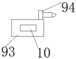
- Authority
- CN
- China
- Prior art keywords
- plate
- vertical plate
- support
- support frame
- supporting
- Prior art date
- Legal status (The legal status is an assumption and is not a legal conclusion. Google has not performed a legal analysis and makes no representation as to the accuracy of the status listed.)
- Expired - Fee Related
Links
Images



Landscapes
- Position Input By Displaying (AREA)
Abstract
本实用新型公开了一种智能互动水晶触控台,包括支撑竖板,所述支撑竖板的上下端分别转动设置安装板和支撑板且安装板的上端面上安装有互动触控屏,所述安装板的下端面和支撑板的上端面上均设有容纳凹槽且容纳凹槽的内腔分别设有第一支撑架和第二支撑架,所述第一支撑架和第二支撑架远离容纳凹槽的一端分别与支撑竖板插接固定,所述支撑竖板的内腔呈上下对称设有固定机构且两组固定机构分别与第一支撑架和第二支撑架插接。本实用新型所述的一种智能互动水晶触控台,在不使用时,可通过反向转动转动块解除插接柱与转动杆的插接固定,并使得安装板和支撑板与支撑竖板贴合,从而减少占用空间。

The utility model discloses an intelligent interactive crystal touch console, which comprises a supporting vertical plate. The upper and lower ends of the supporting vertical plate are respectively rotated to install a mounting plate and a supporting plate, and an interactive touch screen is installed on the upper end surface of the mounting plate. The lower end surface of the mounting plate and the upper end surface of the support plate are provided with accommodating grooves, and the inner cavity of the accommodating groove is respectively provided with a first supporting frame and a second supporting frame, the first supporting frame and the second supporting frame. One end away from the accommodating groove is respectively inserted and fixed with the support vertical plate. The inner cavity of the support vertical plate is symmetrically provided with fixing mechanisms, and two sets of fixing mechanisms are respectively inserted with the first support frame and the second support frame. The intelligent interactive crystal touch console of the utility model can be used to reversely rotate the rotating block to release the plug connection and fixation of the plug column and the rotating rod, and make the installation plate, the support plate and the support vertical plate. fit, thus reducing the footprint.
Description
技术领域technical field
本实用新型涉及智能滑动互动设备领域,特别涉及一种智能互动水晶触控台。The utility model relates to the field of intelligent sliding interactive equipment, in particular to an intelligent interactive crystal touch console.
背景技术Background technique
现有的智能互动水晶触控台(即是智能互动触摸一体机)是集先进的触摸屏、主板、内存、硬盘、显卡等电子元器件组成,与传统PC机的工作原理并无二致,根据触摸屏屏体的大小并配合软件可实现如公众信息查询、广告展示、媒体互动、会议内容展示、线下体验店商品展示等,如配合指纹仪、扫描仪、读卡器、微型打印机等外设,可实现指纹考勤、刷卡、打印等特定需求。The existing intelligent interactive crystal touch console (that is, the intelligent interactive touch all-in-one machine) is composed of advanced touch screen, motherboard, memory, hard disk, graphics card and other electronic components, which is no different from the working principle of traditional PC. The size of the touch screen body and the software can realize such as public information query, advertisement display, media interaction, conference content display, offline experience store product display, etc., such as fingerprint scanners, scanners, card readers, micro printers and other peripherals , which can meet specific needs such as fingerprint attendance, card swiping, and printing.
现有的智能互动水晶触控台为固定式结构,使得其无法进行折叠,在不使用或运输时会占用较大空间,故此,我们提出一种智能互动水晶触控台。The existing intelligent interactive crystal touch console is a fixed structure, so that it cannot be folded, and will occupy a large space when not in use or transported. Therefore, we propose an intelligent interactive crystal touch console.
实用新型内容Utility model content
本实用新型的主要目的在于提供一种智能互动水晶触控台,可以有效解决背景技术中的问题。The main purpose of the present invention is to provide an intelligent interactive crystal touch console, which can effectively solve the problems in the background technology.
为实现上述目的,本实用新型采取的技术方案为:To achieve the above purpose, the technical scheme adopted by the present utility model is:
一种智能互动水晶触控台,包括支撑竖板,所述支撑竖板的上下端分别转动设置安装板和支撑板且安装板的上端面上安装有互动触控屏,所述安装板的下端面和支撑板的上端面上均设有容纳凹槽且容纳凹槽的内腔分别设有第一支撑架和第二支撑架,所述第一支撑架和第二支撑架远离容纳凹槽的一端分别与支撑竖板插接固定,所述支撑竖板的内腔呈上下对称设有固定机构且两组固定机构分别与第一支撑架和第二支撑架插接。An intelligent interactive crystal touch console includes a supporting vertical plate, the upper and lower ends of the supporting vertical plate are respectively rotated to install a mounting plate and a supporting plate, and an interactive touch screen is installed on the upper end surface of the mounting plate, and the lower end of the mounting plate is provided with an interactive touch screen. The end face and the upper end face of the support plate are provided with accommodating grooves, and the inner cavity of the accommodating groove is respectively provided with a first supporting frame and a second supporting frame, and the first supporting frame and the second supporting frame are far away from the accommodating grooves. One end is respectively inserted and fixed with the support vertical plate, the inner cavity of the support vertical plate is symmetrically provided with fixing mechanisms up and down, and two sets of fixing mechanisms are respectively inserted with the first support frame and the second support frame.
优选的,所述第一支撑架和第二支撑架结构相同,所述第二支撑架包括转动杆,所述转动杆呈前后对称设有两组且两组转动杆的下端与支撑板转动连接,两组所述转动杆远离支撑板的一端上均设有插接通孔且两组转动杆之间通过连接杆固定连接。Preferably, the first support frame and the second support frame have the same structure, the second support frame includes a rotating rod, and the rotating rods are symmetrically provided with two sets of front and rear, and the lower ends of the two sets of rotating rods are rotatably connected to the support plate The ends of the two sets of rotating rods away from the support plate are provided with insertion holes, and the two sets of rotating rods are fixedly connected by connecting rods.
优选的,所述固定机构包括转动丝杆,所述转动丝杆转动设置在支撑竖板的内腔,且转动丝杆的右端贯穿支撑竖板的内腔侧壁并延伸至其外布与转动块固定连接,所述转动丝杆上呈左右对称设有移动螺母且两组移动螺母上均固定有插接柱。Preferably, the fixing mechanism includes a rotating screw, the rotating screw is rotatably arranged in the inner cavity of the supporting vertical plate, and the right end of the rotating screw penetrates the inner cavity side wall of the supporting vertical plate and extends to the outer cloth and rotating The blocks are fixedly connected, the rotating screw rods are symmetrically provided with moving nuts on the left and right, and the two groups of moving nuts are fixed with inserting posts.
优选的,所述移动螺母的侧壁上呈对称固定有滑动块且滑动块远离移动螺母的一端与支撑竖板的内腔壁滑动卡接。Preferably, a sliding block is symmetrically fixed on the side wall of the movable nut, and one end of the sliding block away from the movable nut is slidably engaged with the inner cavity wall of the supporting vertical plate.
优选的,所述插接柱的右端设置为锥台型机构。Preferably, the right end of the plug-in column is configured as a frustum-shaped mechanism.
优选的,所述支撑竖板内腔呈左右对称设有回型块且转动杆的下端位于回型块的回型腔内,所述回型块上设有透过孔。Preferably, the inner cavity of the support vertical plate is symmetrically provided with a return block, the lower end of the rotating rod is located in the return cavity of the return block, and the return block is provided with a through hole.
与现有技术相比,本实用新型具有如下有益效果:Compared with the prior art, the utility model has the following beneficial effects:
本实用新型中,设有第一支撑架、第二支撑架和固定机构,在使用时,通过固定机构的插接柱与第一支撑架和第二支撑架上的转动杆插接固定,从而实现安装板和支撑板的固定,不使用时,可通过反向转动转动块解除插接柱与转动杆的插接固定,并使得安装板和支撑板与支撑竖板贴合,从而减少占用空间。In the utility model, a first support frame, a second support frame and a fixing mechanism are provided. When in use, the plug-in column of the fixing mechanism is inserted and fixed with the rotating rods on the first support frame and the second support frame, thereby Realize the fixation of the mounting plate and the supporting plate. When not in use, the plug-in column and the rotating rod can be released by turning the rotating block in the opposite direction, and the mounting plate and the supporting plate can be attached to the supporting vertical plate, thereby reducing the occupied space. .
附图说明Description of drawings
图1为本实用新型一种智能互动水晶触控台的整体结构图;Fig. 1 is the overall structure diagram of a kind of intelligent interactive crystal touch console of the present invention;
图2为本实用新型一种智能互动水晶触控台的支撑板结构图;2 is a structural diagram of a support plate of an intelligent interactive crystal touch console of the present invention;
图3为本实用新型一种智能互动水晶触控台的支撑竖板俯视局部剖面图;3 is a partial cross-sectional top view of a supporting vertical plate of an intelligent interactive crystal touch console of the present invention;
图4为本实用新型一种智能互动水晶触控台的移动螺母结构图;4 is a structural diagram of a moving nut of an intelligent interactive crystal touch console of the present invention;
图5为本实用新型一种智能互动水晶触控台的支撑竖板右视图。5 is a right side view of a supporting vertical plate of an intelligent interactive crystal touch console of the present invention.
图中:1、支撑竖板;2、支撑板;3、安装板;4、互动触控屏;5、第一支撑架;6、容纳凹槽;7、第二支撑架;71、转动杆;72、插接通孔;73、连接杆;8、回型块;9、固定机构;91、转动丝杆;92、转动块;93、移动螺母;94、插接柱;10、滑动块。In the figure: 1. Supporting vertical plate; 2. Supporting plate; 3. Mounting plate; 4. Interactive touch screen; 5. First supporting frame; 6. Receiving groove; 7. Second supporting frame; ;72, inserting through hole; 73, connecting rod; 8, return block; 9, fixing mechanism; 91, rotating screw; 92, rotating block; 93, moving nut; 94, inserting column; 10, sliding block .
具体实施方式Detailed ways
为使本实用新型实现的技术手段、创作特征、达成目的与功效易于明白了解,下面结合具体实施方式,进一步阐述本实用新型。In order to make the technical means, creation features, achievement goals and effects of the present invention easy to understand and understand, the present invention will be further described below with reference to the specific embodiments.
在本实用新型的描述中,需要说明的是,术语“上”、“下”、“内”、“外”“前端”、“后端”、“两端”、“一端”、“另一端”等指示的方位或位置关系为基于附图所示的方位或位置关系,仅是为了便于描述本实用新型和简化描述,而不是指示或暗示所指的装置或元件必须具有特定的方位、以特定的方位构造和操作,因此不能理解为对本实用新型的限制。此外,术语“第一”、“第二”仅用于描述目的,而不能理解为指示或暗示相对重要性。In the description of the present invention, it should be noted that the terms "upper", "lower", "inner", "outer", "front end", "rear end", "two ends", "one end", "the other end" The orientation or positional relationship indicated by "" etc. is based on the orientation or positional relationship shown in the accompanying drawings, and is only for the convenience of describing the present invention and simplifying the description, rather than indicating or implying that the indicated device or element must have a specific orientation, so as to The specific orientation configuration and operation is therefore not to be construed as a limitation of the present invention. Furthermore, the terms "first" and "second" are used for descriptive purposes only and should not be construed to indicate or imply relative importance.
在本实用新型的描述中,需要说明的是,除非另有明确的规定和限定,术语“安装”、“设置有”、“连接”等,应做广义理解,例如“连接”,可以是固定连接,也可以是可拆卸连接,或一体地连接;可以是机械连接,也可以是电连接;可以是直接相连,也可以通过中间媒介间接相连,可以是两个元件内部的连通。对于本领域的普通技术人员而言,可以具体情况理解上述术语在本实用新型中的具体含义。In the description of the present utility model, it should be noted that, unless otherwise expressly specified and limited, the terms "installed", "provided with", "connected", etc., should be understood in a broad sense, for example, "connected" may be a fixed The connection can also be a detachable connection, or an integral connection; it can be a mechanical connection or an electrical connection; it can be a direct connection, or an indirect connection through an intermediate medium, and it can be internal communication between two components. For those of ordinary skill in the art, the specific meanings of the above terms in the present invention can be understood in specific situations.
如图1-5所示,一种智能互动水晶触控台,包括支撑竖板1,支撑竖板1的上下端分别转动设置安装板3和支撑板2且安装板3的上端面上安装有互动触控屏4,安装板3的下端面和支撑板2的上端面上均设有容纳凹槽6且容纳凹槽6的内腔分别设有第一支撑架5和第二支撑架7,第一支撑架5和第二支撑架7远离容纳凹槽6的一端分别与支撑竖板1插接固定,支撑竖板1的内腔呈上下对称设有固定机构9且两组固定机构9分别与第一支撑架5和第二支撑架7插接。As shown in Figures 1-5, an intelligent interactive crystal touch console includes a supporting
第一支撑架5和第二支撑架7结构相同,第二支撑架7包括转动杆71,转动杆71呈前后对称设有两组且两组转动杆71的下端与支撑板2转动连接,两组转动杆71远离支撑板2的一端上均设有插接通孔72且两组转动杆71之间通过连接杆73固定连接,通过第一支撑架5和第二支撑架7与支撑竖板1插接,从而形成对安装板3和支撑板2的支撑。The
固定机构9包括转动丝杆91,转动丝杆91转动设置在支撑竖板1的内腔,且转动丝杆91的右端贯穿支撑竖板1的内腔侧壁并延伸至其外布与转动块92固定连接,转动丝杆91上呈左右对称设有移动螺母93且两组移动螺母93上均固定有插接柱94,通过固定机构9的插接柱94与转动杆71插接,从而实现对第一支撑架5和第二支撑架7的固定,最终使得安装板3和支撑板2得到固定。The
移动螺母93的侧壁上呈对称固定有滑动块10且滑动块10远离移动螺母93的一端与支撑竖板1的内腔壁滑动卡接,便于移动螺母93在支撑竖板1内稳定移动。The
插接柱94的右端设置为锥台型机构,便于插接柱94与转动杆71上设有的插接通孔72的导向插接。The right end of the plug-in
支撑竖板1内腔呈左右对称设有回型块8且转动杆71的下端位于回型块8的回型腔内,回型块8上设有透过孔,通过回型块8实现对转动杆71的杆体的部分容纳和对杆体的支撑,插接柱94可穿过透过孔与转动杆71插接,从而实现转动杆71的固定。The inner cavity of the support
需要说明的是,本实用新型为一种智能互动水晶触控台,本触控台在使用时,可通过转动支撑板2,使得原本与支撑竖板1贴合的支撑板2与支撑竖板1呈九十度垂直设置,再转动支撑板2上的转动杆71使得两组转动杆71远离支撑板2的一端运动到回型块8的回型腔内,转动转动块92,使得两组移动螺母93带动两组插接柱94做相对运动,当插接柱94穿过会回型块8的侧壁上设有的透过孔并贯穿插接通孔72即可,此时通过插接柱94的作用,从而实现对转动杆71的固定,最终实现对支撑板2的固定,使得支撑板2对支撑竖板1进行支撑,再转动安装板3,使得安装板3倾斜一定角度并将安装板3上的第一支撑架5的转动杆71下端插入回型块8的内腔,并通过转动上方的转动块92使得插接柱94与转动杆71插接,从而实现对安装板3的固定支撑,在不使用时,可通过阀反向转动转动块92解除插接柱94对转动杆71的插接固定,并使得转动杆71位于容纳凹槽6内,最后转动安装板3和支撑板2使得其均与支撑竖板1贴合,从而减少占用空间。It should be noted that the present invention is an intelligent interactive crystal touch console. When the touch console is in use, the
以上显示和描述了本实用新型的基本原理和主要特征和本实用新型的优点。本行业的技术人员应该了解,本实用新型不受上述实施例的限制,上述实施例和说明书中描述的只是说明本实用新型的原理,在不脱离本实用新型精神和范围的前提下,本实用新型还会有各种变化和改进,这些变化和改进都落入要求保护的本实用新型范围内。本实用新型要求保护范围由所附的权利要求书及其等效物界定。The basic principles and main features of the present invention and the advantages of the present invention are shown and described above. It should be understood by those skilled in the art that the present invention is not limited by the above-mentioned embodiments. The above-mentioned embodiments and descriptions only illustrate the principle of the present invention. Without departing from the spirit and scope of the present invention, the present invention There will also be various changes and improvements in the new model, which all fall within the scope of the claimed invention. The claimed scope of the present invention is defined by the appended claims and their equivalents.
Claims (6)
Priority Applications (1)
| Application Number | Priority Date | Filing Date | Title |
|---|---|---|---|
| CN202020280406.0U CN210831269U (en) | 2020-03-10 | 2020-03-10 | An intelligent interactive crystal touch console |
Applications Claiming Priority (1)
| Application Number | Priority Date | Filing Date | Title |
|---|---|---|---|
| CN202020280406.0U CN210831269U (en) | 2020-03-10 | 2020-03-10 | An intelligent interactive crystal touch console |
Publications (1)
| Publication Number | Publication Date |
|---|---|
| CN210831269U true CN210831269U (en) | 2020-06-23 |
Family
ID=71281630
Family Applications (1)
| Application Number | Title | Priority Date | Filing Date |
|---|---|---|---|
| CN202020280406.0U Expired - Fee Related CN210831269U (en) | 2020-03-10 | 2020-03-10 | An intelligent interactive crystal touch console |
Country Status (1)
| Country | Link |
|---|---|
| CN (1) | CN210831269U (en) |
-
2020
- 2020-03-10 CN CN202020280406.0U patent/CN210831269U/en not_active Expired - Fee Related
Similar Documents
| Publication | Publication Date | Title |
|---|---|---|
| CN209788983U (en) | A hidden computer desk | |
| CN211065512U (en) | Hidden computer input device for theoretical calculation | |
| CN209167959U (en) | A kind of adjustable interactive intelligent tablet computer | |
| CN208141310U (en) | A kind of easy-to-dismount computer box structure of computer teaching | |
| CN220828728U (en) | Wall-mounted touch all-in-one machine | |
| CN210822263U (en) | A train seat table | |
| CN201527611U (en) | Computer case | |
| CN220303149U (en) | Touch all-in-one convenient to remove | |
| CN115736520A (en) | Device convenient for Chinese language and literature query and reading and using method thereof | |
| CN110703871B (en) | A modular easy-swap computer case | |
| CN211779966U (en) | A new type of rotatable electronic information display board | |
| CN213522782U (en) | A high-strength PCB motherboard | |
| CN221225431U (en) | A graphics card support bracket for a computer host | |
| CN219076894U (en) | A nano blackboard hanging wall installation structure | |
| CN221997287U (en) | Wall-hung book cabinet | |
| CN209980142U (en) | Integrated master control computer board card | |
| CN220233670U (en) | nvmeM 2-SATA 6G5 port expansion card | |
| CN216596084U (en) | Dual-screen tablet for teaching | |
| CN215679279U (en) | Computer case capable of quickly disassembling computer mainboard | |
| CN219916667U (en) | A stable acrylic display board | |
| CN213524331U (en) | Ideological and political theory teaching is with multi-media lectern | |
| CN210574350U (en) | A computer teaching aid device applied to the subject of information technology | |
| CN207992885U (en) | A kind of liquid crystal display that two-way can be used | |
| CN207428785U (en) | A kind of finance shelf post | |
| CN216280240U (en) | Multifunctional touch machine |
Legal Events
| Date | Code | Title | Description |
|---|---|---|---|
| GR01 | Patent grant | ||
| GR01 | Patent grant | ||
| CF01 | Termination of patent right due to non-payment of annual fee | ||
| CF01 | Termination of patent right due to non-payment of annual fee |
Granted publication date: 20200623 |