CN210828263U - Steel structure support system for installing carriageway - Google Patents
Steel structure support system for installing carriageway Download PDFInfo
- Publication number
- CN210828263U CN210828263U CN201921363207.XU CN201921363207U CN210828263U CN 210828263 U CN210828263 U CN 210828263U CN 201921363207 U CN201921363207 U CN 201921363207U CN 210828263 U CN210828263 U CN 210828263U
- Authority
- CN
- China
- Prior art keywords
- embedded part
- installing
- embedded
- bolt holes
- vertical rod
- Prior art date
- Legal status (The legal status is an assumption and is not a legal conclusion. Google has not performed a legal analysis and makes no representation as to the accuracy of the status listed.)
- Active
Links
- 229910000831 Steel Inorganic materials 0.000 title claims abstract description 56
- 239000010959 steel Substances 0.000 title claims abstract description 56
- 230000000149 penetrating effect Effects 0.000 claims description 4
- 238000009434 installation Methods 0.000 description 6
- 239000004567 concrete Substances 0.000 description 4
- 238000010276 construction Methods 0.000 description 4
- 238000005034 decoration Methods 0.000 description 3
- 230000015572 biosynthetic process Effects 0.000 description 1
- 230000000694 effects Effects 0.000 description 1
- 238000012423 maintenance Methods 0.000 description 1
- 238000000034 method Methods 0.000 description 1
- 238000012986 modification Methods 0.000 description 1
- 230000004048 modification Effects 0.000 description 1
- 238000007789 sealing Methods 0.000 description 1
- 238000006467 substitution reaction Methods 0.000 description 1
- 238000003466 welding Methods 0.000 description 1
Images

Landscapes
- Bridges Or Land Bridges (AREA)
Abstract
The utility model discloses a steel structure bracket system for installing a packway, which is arranged on a stand and is matched and connected with three adjacent steps of the stand, and comprises an embedded part embedded in the step at the bottom and a movable support frame covering the three steps; the embedded parts are distributed along the length of the step and comprise upper embedded parts and lower embedded parts connected with the upper embedded parts, the lower embedded parts are fixed in the step, the upper surfaces of the lower embedded parts are flush with the upper surface of the step, and the upper embedded parts are detachably connected with the movable support frame; the movable support frame comprises two supporting pieces and an operating platform above the two supporting pieces; the support piece comprises a vertical rod arranged in the vertical direction, a transverse rod connected with the vertical rod and arranged in the horizontal direction, and an inclined strut rod arranged in an inclined mode, one end of the inclined strut rod is connected with the vertical rod, the other end of the inclined strut rod is connected to the middle of the transverse rod, and the outer cantilever part is supported on the uppermost step.
Description
Technical Field
The utility model relates to a construction articles for use technical field, concretely relates to steel structure support system for installing packway.
Background
With the continuous progress of Chinese economy, the spiritual culture needs of people can be better released, and based on the population and market advantages of China, the theme park is continuously increased and expanded, so that the continuously-increased market of leisure and entertainment tourists is well met, and the performance hall is an important component of the theme park and is an important place for people to watch performances.
A large amount of stage mechanical facilities, pipelines, controllers, lighting equipment and the like are hung above the performance hall, a steel structure truss is large in span, light in structure and fast to install, the steel structure truss is the first choice of a roof structure of the performance hall, and a packway is hung at the bottom of a roof steel structure truss to provide a bearing platform for installation, debugging and maintenance workers of the equipment.
The installation method of the prior fairway comprises the following steps: after the roof structure is installed, the berm is installed, and the berm is installed and listed in the interior decoration engineering of the construction of the performance hall, so that the construction progress is slow, and the stair-shaped steps in the performance hall cannot be directly stacked in the berm structure due to roof sealing.
SUMMERY OF THE UTILITY MODEL
The above-mentioned not enough to prior art exists, the utility model aims to solve how because the roof capping for the unable problem in directly stacking the packway structure of echelonment step in the performance hall provides one kind now before the packway structure hoist and mount, the steel structure support system who is used for installing the packway of interim fixed echelonment step.
The technical scheme adopted by the invention is as follows:
a steel structure support system for installing the packway, steel structure support system installs on the stand to it links to each other its characterized in that with the cooperation of the three adjacent step of stand: the steel structure support system comprises an embedded part embedded in the lowest step and a movable support frame covering the three steps; the embedded parts are distributed along the length of the step and comprise fixed embedded parts fixed in the step, and the fixed embedded parts are detachably connected with the movable support frame; the number of the movable support frames is at least one, and the movable support frames comprise two support pieces and an operation platform above the two support pieces;
the supporting piece comprises a vertical rod arranged in the vertical direction, a transverse rod connected with the vertical rod and arranged in the horizontal direction, and an inclined stay bar arranged in an inclined mode, one end of the inclined stay bar is connected with the vertical rod, the other end of the inclined stay bar is connected to the middle of the transverse rod, so that the part, far away from the inclined stay bar, of the transverse rod forms an outward-picking part, and the outward-picking part is supported on the uppermost step.
The utility model discloses before the hoisting of packway structure, install movable support frame on the step of below through the built-in fitting, the part is chosen outward to the transverse bar in movable support frame's the support piece and is placed at the step upper surface of keeping away from the built-in fitting, make movable support frame can fix the step, the packway constitutional unit has been placed to the transverse bar upper surface on the movable support frame on three adjacent step, because fixed buried piece can be dismantled with movable support frame and be connected, after the packway constitutional unit installation finishes, dismantle fixed buried piece and movable support frame, and move movable support frame to next three adjacent step, analogize with this, every three adjacent step is as packway constitutional unit's support section, and like this, just make the installation of a regional packway structure accomplish.
Further, fixed piece of burying is including last piece of burying and the lower piece of burying of being connected with last piece of burying, down bury the piece and fix in the step, just the upper surface of lower piece of burying is parallel and level with the upper surface of step, go up to bury the piece and can dismantle with vertical pole and be connected.
The embedded part is divided into an upper part and a lower part which are respectively an upper embedded part and a lower embedded part, the upper embedded part is connected with the vertical rod, the lower embedded part is fixed in the step, and the vertical rod is fixed on the step through the embedded part. And then, the embedded part and the vertical rod can be disassembled, and the embedded part can be transferred to the next area for continuous use.
Furthermore, the embedded part further comprises a connecting steel plate, a plurality of first bolt holes are formed in the connecting steel plate, a plurality of second bolt holes corresponding to the first bolt holes in the upper half part of the connecting steel plate are formed in the upper portion of the upper embedded part, a plurality of third bolt holes corresponding to the first bolt holes in the lower half part of the connecting steel plate are formed in the bottom of the vertical rod, the connecting steel plate is connected with the upper portion of the upper embedded part through bolts penetrating through the first bolt holes and the second bolt holes, and the connecting steel plate is connected with the bottom of the vertical rod through bolts penetrating through the first bolt holes and the third bolt holes.
The design is like this, will go up through connection steel sheet and bury the piece and link to each other with vertical pole to highly finely tuning that connection steel sheet and last buried piece are connected through a plurality of first bolt holes and second bolt hole, simultaneously, vertical pole bottom finely tunes the height of vertical pole through a plurality of first bolt holes and third bolt hole, and the integral adjustment is fit for the horse way constitutional unit and supports the height.
Further, the length of the step fixed by the lower embedded part is greater than the thickness of 1/2 step and less than the thickness of 3/4 step. The design is that the lower embedded part can be stably fixed in the step.
Furthermore, the embedded part adopts H-shaped steel, the outer sides of the two flange plates of the embedded part are respectively provided with a floating plate, and the two ends of the floating plate respectively extend to the edges of the two sides of the flange plates. This is designed to prevent subsidence of the embedment into the uncured concrete.
Further, the upper surface of the floating plate is flush with the upper surface of the lower embedded part. By the design, the lower embedded part can be positioned in the step, and the upper embedded part is positioned above the upper surface of the step.
Further, the upper surface of the floating plate and the upper surface of the step are on the same horizontal plane. When the stand concretes, the floating plate provides buoyancy for the upper embedded part, so that the upper embedded part cannot sink into the step.
Further, the distance between the top surface of the vertical rod and the upper surface of the transverse rod is 200 mm. By the design, the vertical rods play a side supporting role for the packway structure unit.
Compared with the prior art, the utility model has the advantages of as follows:
1. the utility model discloses before the hoisting of packway structure, to installing a plurality of steel structure support on the step, support packway constitutional unit by steel structure support, constitute an regional packway structure by a plurality of packway constitutional unit, design like this, can effectual solution packway structure hoist the preceding temporary fixation difficult problem on the echelonment step.
2. The utility model discloses a steel structure support simple structure, and can dismantle the connection through vertical pole and built-in fitting, can have enough to meet the need the use, it is with low costs.
3. The utility model discloses treat all packway structural installation back that finishes, utilize the cutting machine to cut off the last embedded part that the built-in fitting exceeds the step, alright guarantee the surface smoothness of step, can not lead to the fact the influence to the decoration and finishing engineering of follow-up step.
Drawings
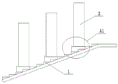
Figure 1 is the utility model discloses a steel construction support system structure sketch map for installing packway.
Fig. 2 is an enlarged view at a1 of fig. 1.
In the figure: the structure comprises a step 1, a pavement structure unit 2, transverse rods 3, inclined support rods 4, vertical rods 5, connecting steel plates 6, a floating plate 7 and embedded parts 8.
Detailed Description
The present invention will be further explained with reference to the drawings and examples.
In this embodiment: referring to fig. 1 and 2, a steel structure support system for installing the packway, steel structure support system installs on the stand to link to each other with the cooperation of three adjacent step 1 of stand, steel structure support system is including the built-in fitting 8 of inlaying in one step 1 of below, and the built-in fitting 8 is a plurality of and along the length distribution of step, and it includes fixed embedded part, and fixed embedded part includes upper embedded part and lower embedded part, and lower embedded part is fixed in step 1, and the upper surface of lower embedded part is parallel and level with the upper surface of step 1.
Steel structure support is still including the movable support frame that covers three step 1, the fixed piece that buries can be dismantled with movable support frame and be connected, movable support frame is at least one, it includes the operation platform of two support pieces and two support piece tops, support piece includes vertical rod 5 that vertical direction set up, horizontal pole 3 and diagonal brace 4 that the horizontal direction set up, 4 one ends of diagonal brace link to each other with vertical rod 5, the 4 other ends of diagonal brace are connected at 3 middle parts of horizontal pole, make horizontal pole 3 keep away from the partial formation of diagonal brace 4 and choose the part outward, it supports on step 1 of the top to choose the part outward, diagonal brace 4, horizontal pole 3 and vertical rod 5 constitute stable triangle structure through the welding, vertical rod 5, horizontal pole 3 and diagonal brace 4 are H shaped steel.
The upper embedded part is detachably connected with the vertical rod 5, the embedded part 8 is divided into an upper part and a lower part which are respectively the upper embedded part and the lower embedded part, the upper embedded part is connected with the vertical rod 5 through the upper embedded part, the lower embedded part is fixed in the step 1, and the length of the lower embedded part fixed on the step 1 is larger than 1/2 of the thickness of the step 1 and smaller than 3/4 of the thickness of the step 1. The design is that the lower embedded part can be firmly fixed in the step 1.
Vertical pole 5 passes through built-in fitting 8 to be fixed on step 1, and vertical pole 5 links to each other with built-in fitting 8 through connecting steel plate 6, be provided with a plurality of first bolt holes on connecting steel plate 6, it is provided with a plurality of second bolt holes corresponding with the first bolt hole of the first half of connecting steel plate 6 to go up embedded part upper portion, be provided with a plurality of third bolt holes corresponding with the first bolt hole of the first half of connecting steel plate 6 on vertical pole 5 bottom, connecting steel plate 6 links to each other with last embedded part upper portion through the bolt that passes first bolt hole and second bolt hole, connecting steel plate 6 links to each other with vertical pole 5 bottom through the bolt that passes first bolt hole and third bolt hole.
Design like this, will go up through connector plate 6 and bury the piece and link to each other with vertical pole 5 to highly finely tune that connector plate 6 and last piece of burying are connected through a plurality of first bolt holes and second bolt hole, simultaneously, vertical pole 5 bottoms highly finely tunes vertical pole 5 through a plurality of first bolt holes and third bolt hole, and the overall regulation is fit for 2 bearing heights of packway constitutional unit.
In addition, the embedded part 8 is made of H-shaped steel, the outer sides of two flange plates of the embedded part 8 are respectively provided with a floating plate 7, and two ends of the floating plate 7 respectively extend to two side edges of the flange plates. This is designed to prevent the embedment 8 from sinking into the uncured concrete.
The upper surface of the floating plate 7 is flush with the upper surface of the lower embedded part. By the design, the lower embedded part can be positioned in the step 1, and the upper embedded part is positioned above the upper surface of the step 1.
The upper surface of the floating plate 7 and the upper surface of the step 1 are in the same horizontal plane. When the stand is poured with concrete, the floating plate 7 provides buoyancy for the upper embedded part, so that the upper embedded part cannot sink into the step 1.
Wherein, 3 flange plate upper surface of horizontal pole are fixed with the packway constitutional unit 2, and 5 top surfaces of vertical pole have the distance with the upper surface of 3 flange plate one ends of horizontal pole, and wherein, the distance is 200mm, designs like this for vertical pole 5 plays the effect that the side was strutted to packway constitutional unit 2.
In addition, the top surface of the vertical rod 5 is spaced from the upper surface of one end of the flange plate of the transverse rod 3. The included angle between the vertical rod 5 and the transverse rod 3 is 90 degrees. The design is such that the vertical rods 5 and the transverse rods 3 are kept vertical, and the structural size and the arrangement number of the vertical rods are determined according to the width of the pavement structure and the width and height of each step of the stand.
The utility model discloses before the hoisting of horse way structure, to installing a plurality of steel structure support on step 1, support horse way constitutional unit 2 by steel structure support, constitute an regional horse way structure by a plurality of horse way constitutional unit 2, fix 3 one ends of the transverse bar of support piece in a echelonment step 1 through 5 bottom built-in fittings 8 of vertical pole, the part of choosing outward of the 3 other ends of transverse bar is placed at step 1 upper surface of keeping away from built-in fittings 8 for step 1 is fixed.
The steps 1 are three adjacent steps 1, the pavement structure units 2 are placed on the upper surface of the flange plate of the transverse rod 3, and by analogy, every three adjacent steps 1 are used as supporting sections of the pavement structure units 2, so that the pavement structure installation of one area is completed. And then, the embedded part 8 and the vertical H-shaped rod can be detached, and the embedded part can be transferred to the next area for continuous use.
After all the pavement structures are installed, the upper embedded parts of the embedded parts 8 higher than the steps 1 are cut off by using a cutting machine, so that the surface flatness of the steps 1 can be ensured, and the subsequent decoration project of the steps 1 cannot be influenced.
Finally, it should be noted that the above embodiments are only used for illustrating the technical solutions of the present invention and not for limiting the technical solutions, and those skilled in the art should understand that those modifications or equivalent substitutions can be made to the technical solutions of the present invention without departing from the spirit and scope of the technical solutions, and all should be covered in the scope of the claims of the present invention.
Claims (8)
1. A steel structure support system for installing the packway, steel structure support system installs on the stand to it links to each other its characterized in that with the cooperation of the three adjacent step of stand: the steel structure support system comprises an embedded part embedded in the lowest step and a movable support frame covering the three steps; the embedded parts are distributed along the length of the step and comprise fixed embedded parts fixed in the step, and the fixed embedded parts are detachably connected with the movable support frame; the number of the movable support frames is at least one, and the movable support frames comprise two support pieces and an operation platform above the two support pieces;
the supporting piece comprises a vertical rod arranged in the vertical direction, a transverse rod connected with the vertical rod and arranged in the horizontal direction, and an inclined stay bar arranged in an inclined mode, one end of the inclined stay bar is connected with the vertical rod, the other end of the inclined stay bar is connected to the middle of the transverse rod, so that the part, far away from the inclined stay bar, of the transverse rod forms an outward-picking part, and the outward-picking part is supported on the uppermost step.
2. The steel structure support system for installing the riding channel according to claim 1, wherein the fixing embedded part comprises an upper embedded part and a lower embedded part connected with the upper embedded part, the lower embedded part is fixed in the step, the upper surface of the lower embedded part is flush with the upper surface of the step, and the upper embedded part is detachably connected with the vertical rod.
3. The steel structure bracket system for installing the horse way according to claim 2, wherein the embedded part further comprises a connecting steel plate, a plurality of first bolt holes are formed in the connecting steel plate, a plurality of second bolt holes corresponding to the first bolt holes in the upper half part of the connecting steel plate are formed in the upper part of the upper embedded part, a plurality of third bolt holes corresponding to the first bolt holes in the lower half part of the connecting steel plate are formed in the bottom part of the vertical rod, the connecting steel plate is connected with the upper part of the upper embedded part through bolts penetrating through the first bolt holes and the second bolt holes, and the connecting steel plate is connected with the bottom part of the vertical rod through bolts penetrating through the first bolt holes and the third bolt holes.
4. The steel structural support system for installing a horse way according to claim 2, wherein the length of the step is greater than 1/2 and less than 3/4.
5. The steel structure bracket system for installing the horse way according to any one of claims 1 to 4, wherein the embedded part is made of H-shaped steel, a floating plate is respectively arranged on the outer sides of two flange plates of the embedded part, and two ends of the floating plate respectively extend to two side edges of the flange plates.
6. The steel structural support system for installing a horse way according to claim 5, wherein the upper surface of the floating plate is flush with the upper surface of the lower buried member.
7. The steel structural support system for installing a horse way according to claim 5, wherein the upper surface of the floating plate and the upper surface of the step are on the same horizontal plane.
8. A steel structural support system for installing a horse way according to claim 1, wherein the distance between the top surface of the vertical rod and the upper surface of the horizontal rod is 200 mm.
Priority Applications (1)
| Application Number | Priority Date | Filing Date | Title |
|---|---|---|---|
| CN201921363207.XU CN210828263U (en) | 2019-08-21 | 2019-08-21 | Steel structure support system for installing carriageway |
Applications Claiming Priority (1)
| Application Number | Priority Date | Filing Date | Title |
|---|---|---|---|
| CN201921363207.XU CN210828263U (en) | 2019-08-21 | 2019-08-21 | Steel structure support system for installing carriageway |
Publications (1)
| Publication Number | Publication Date |
|---|---|
| CN210828263U true CN210828263U (en) | 2020-06-23 |
Family
ID=71270437
Family Applications (1)
| Application Number | Title | Priority Date | Filing Date |
|---|---|---|---|
| CN201921363207.XU Active CN210828263U (en) | 2019-08-21 | 2019-08-21 | Steel structure support system for installing carriageway |
Country Status (1)
| Country | Link |
|---|---|
| CN (1) | CN210828263U (en) |
Cited By (1)
| Publication number | Priority date | Publication date | Assignee | Title |
|---|---|---|---|---|
| CN111840861A (en) * | 2020-08-13 | 2020-10-30 | 华电重工股份有限公司 | A fire-fighting device for closed coal yard |
-
2019
- 2019-08-21 CN CN201921363207.XU patent/CN210828263U/en active Active
Cited By (1)
| Publication number | Priority date | Publication date | Assignee | Title |
|---|---|---|---|---|
| CN111840861A (en) * | 2020-08-13 | 2020-10-30 | 华电重工股份有限公司 | A fire-fighting device for closed coal yard |
Similar Documents
| Publication | Publication Date | Title |
|---|---|---|
| CN108560719B (en) | Supporting and mounting method for super-large-span double-layer bidirectional suspension cable structure | |
| CN110424746B (en) | Method for installing roof truss and pavement in venue | |
| KR100991262B1 (en) | Method for bridge reinforcement and landscape architecture | |
| CN110396919B (en) | Assembled steel structure-concrete combined bridge and construction method thereof | |
| CN206308654U (en) | Prefabricated assembled railing | |
| CN110820553A (en) | Combined prefabricated bridge guardrail | |
| CN107761542A (en) | One kind arch oblique pull combined system bridge and its construction method | |
| CN102277836B (en) | Construction method of tilting concrete tower base | |
| CN103075016B (en) | Installing method of extendable latticed shell structure | |
| KR101193470B1 (en) | Bearing and constructing method for bridge | |
| KR101204966B1 (en) | Construction method for confine concrete member of steel plate girder with reinforced bending moment | |
| CN107724244B (en) | Temporary T-shaped structure formed by bridge sections of continuous rigid frame edges without support and construction method of temporary T-shaped structure | |
| CN108999290B (en) | Combined lifting method for flexible cable net at lower part of cable bearing grid structure | |
| KR101130166B1 (en) | Apparatus and method for replacing bearings of box girder bridge | |
| CN115787504B (en) | Hanger platform and construction method of hollow tower pier top solid section | |
| KR101265098B1 (en) | Assembly type guard rail | |
| RU114475U1 (en) | MOBILE ANTENNA SUPPORT | |
| CN216108042U (en) | Concrete track bridge pillar system | |
| KR200433150Y1 (en) | Fixture for street lamp post | |
| CN203531349U (en) | Novel high-bearing easily-dismantled overhanging type scaffold | |
| CN113882244A (en) | A concrete track bridge pillar system and its adjustment method for dealing with ground subsidence | |
| CN211646965U (en) | Reinforced column base of viewing platform | |
| CN113737661A (en) | Construction method for steel-concrete combined section of tower base of cable-stayed bridge | |
| CN107815976B (en) | A kind of construction method of multi-joint continuous beam or multi-joint rigid structure beam end bay straight line beam section | |
| CN111893897B (en) | Supporting device for bridge capping beam construction and bridge capping beam construction method |
Legal Events
| Date | Code | Title | Description |
|---|---|---|---|
| GR01 | Patent grant | ||
| GR01 | Patent grant |