CN210821014U - Automatic lens taking device for separating lens from mold - Google Patents
Automatic lens taking device for separating lens from mold Download PDFInfo
- Publication number
- CN210821014U CN210821014U CN201921179986.8U CN201921179986U CN210821014U CN 210821014 U CN210821014 U CN 210821014U CN 201921179986 U CN201921179986 U CN 201921179986U CN 210821014 U CN210821014 U CN 210821014U
- Authority
- CN
- China
- Prior art keywords
- lens
- separating
- taking device
- mold
- automatic
- Prior art date
- Legal status (The legal status is an assumption and is not a legal conclusion. Google has not performed a legal analysis and makes no representation as to the accuracy of the status listed.)
- Active
Links
Images


Landscapes
- Moulds For Moulding Plastics Or The Like (AREA)
Abstract
本实用新型公开了一种用于从模具上分离镜片的自动取镜片装置,属于隐形眼镜取镜片技术领域。一种用于从模具上分离镜片的自动取镜片装置,包括固定座,所述固定座的顶部连接有平移驱动电机,所述第一支撑板上连接有挤压驱动电机,所述挤压驱动电机的输出端连接有移动齿条,且所述固定齿条和移动齿条之间连接有上模本体,所述固定座的侧壁还连接有吸盘升降驱动气缸,所述吸盘升降驱动气缸的输出端连接有吸盘旋转驱动气缸,所述吸盘旋转驱动气缸的输出端连接有与上模本体相配合的取镜片吸盘;本实用新型提供的自动取隐形眼镜片装置可以与自动供料设备对接,无需人工放料,可以自动脱出多个隐形眼镜片,大大提高了生产效率,节约了成本。

The utility model discloses an automatic lens-taking device for separating lenses from a mold, which belongs to the technical field of lens-taking for contact lenses. An automatic lens removal device for separating lenses from a mold, comprising a fixed seat, a translation drive motor is connected to the top of the fixed seat, a squeeze drive motor is connected to the first support plate, and the squeeze drive motor is connected to the top of the fixed seat. The output end of the motor is connected with a moving rack, and the upper die body is connected between the fixed rack and the moving rack, and the side wall of the fixed seat is also connected with a suction cup lift driving cylinder, the suction cup lift driving the cylinder. The output end is connected with a suction cup rotating driving cylinder, and the output end of the suction cup rotating driving cylinder is connected with a lens taking suction cup matched with the upper mold body; the automatic contact lens taking device provided by the utility model can be connected with the automatic feeding equipment, Without manual feeding, multiple contact lenses can be automatically released, which greatly improves production efficiency and saves costs.
Description
技术领域technical field
本实用新型涉及隐形眼镜取镜片技术领域,尤其涉及一种用于从模具上分离镜片的自动取镜片装置。The utility model relates to the technical field of taking lenses out of contact lenses, in particular to an automatic lens taking device for separating lenses from molds.
背景技术Background technique
在隐形眼镜的生产制造过程中,隐形眼镜片由上、下模合模制作而成,脱膜后镜片粘附在上模曲面上,需使用脱膜装置取出镜片,现有的设备使用人工取镜片,人工将含有镜片的上模放入半自动工装上,然后挤压上模,最后人工用吸盘取出镜片,每次只能取出一个镜片,现有设备生产率很低,无法满足自动化生产的需求。In the production process of contact lenses, the contact lens is made of upper and lower molds. After the film is released, the lens is adhered to the curved surface of the upper mold. It is necessary to use a release device to take out the lens. For lenses, manually put the upper mold containing the lens into the semi-automatic tooling, then squeeze the upper mold, and finally manually take out the lens with a suction cup, only one lens can be taken out at a time, the productivity of the existing equipment is very low, and cannot meet the needs of automatic production.
实用新型内容Utility model content
本实用新型的目的是为了解决现有技术中存在的问题,而提出的一种用于从模具上分离镜片的自动取镜片装置。The purpose of the utility model is to solve the problems existing in the prior art, and proposes an automatic lens-taking device for separating lenses from molds.
为了实现上述目的,本实用新型采用了如下技术方案:In order to achieve the above-mentioned purpose, the utility model adopts the following technical solutions:
一种用于从模具上分离镜片的自动取镜片装置,包括固定座,所述固定座的顶部连接有平移驱动电机,所述平移驱动电机的输出端连接有第一支撑板,所述第一支撑板上连接有挤压驱动电机,所述挤压驱动电机的输出端连接有移动齿条,所述固定座的顶部还连接有与移动齿条相配合的固定齿条,且所述固定齿条和移动齿条之间连接有上模本体,所述固定座的侧壁还连接有吸盘升降驱动气缸,所述吸盘升降驱动气缸的输出端连接有吸盘旋转驱动气缸,所述吸盘旋转驱动气缸的输出端连接有与上模本体相配合的取镜片吸盘。An automatic lens-taking device for separating lenses from a mold, comprising a fixed seat, a translational drive motor is connected to the top of the fixed seat, an output end of the translational drive motor is connected with a first support plate, the first support plate is The support plate is connected with an extrusion drive motor, the output end of the extrusion drive motor is connected with a moving rack, the top of the fixed seat is also connected with a fixed rack matched with the moving rack, and the fixed tooth The upper die body is connected between the rack and the moving rack, the side wall of the fixed seat is also connected with a suction cup lift drive cylinder, the output end of the suction cup lift drive cylinder is connected with a suction cup rotation drive cylinder, and the suction cup rotation drive cylinder The output end of the lens is connected with a lens-taking suction cup matched with the upper mold body.
优选的,所述固定座内还连接有滑板,所述第一支撑板滑动连接在滑板上。Preferably, a sliding plate is also connected in the fixing seat, and the first supporting plate is slidably connected on the sliding plate.
优选的,所述滑板上设有滑槽,所述第一支撑板滑动连接在滑槽内。Preferably, the slide plate is provided with a chute, and the first support plate is slidably connected in the chute.
优选的,所述滑板的顶部外壁连接有上模驱动气缸,所述上模驱动气缸的输出端连接有上模托板,所述上模本体连接在上模托板上。Preferably, an upper die driving cylinder is connected to the top outer wall of the sliding plate, an upper die supporting plate is connected to the output end of the upper die driving cylinder, and the upper die body is connected to the upper die supporting plate.
优选的,所述固定座内设有凹槽,所述凹槽内连接有与上模本体相配合的接上模漏斗。所述接上模漏斗的顶部连接有漏嘴。Preferably, the fixing seat is provided with a groove, and the groove is connected with an upper mold connection funnel matched with the upper mold body. A leak nozzle is connected to the top of the upper mold funnel.
优选的,所述挤压驱动电机的输出端连接有第二支撑板,所述移动齿条连接在第二支撑板的外壁。Preferably, the output end of the extrusion driving motor is connected with a second support plate, and the moving rack is connected with the outer wall of the second support plate.
优选的,所述第二支撑板滑动连接在第一支撑板的外壁。Preferably, the second support plate is slidably connected to the outer wall of the first support plate.
优选的,所述吸盘旋转驱动气缸的输出端连接有固定架,所述固定架上连接有固定杆,所述取镜片吸盘连接在固定杆的外壁。Preferably, the output end of the suction cup rotation driving cylinder is connected with a fixing frame, the fixing frame is connected with a fixing rod, and the lens taking suction cup is connected with the outer wall of the fixing rod.
优选的,所述固定座的顶部外壁连接有挡板,所述平移驱动电机连接在挡板内。Preferably, a baffle is connected to the top outer wall of the fixed seat, and the translation drive motor is connected in the baffle.
优选的,所述固定座的底部连接有固定板,所述固定板内开凿有螺纹孔。Preferably, a fixing plate is connected to the bottom of the fixing seat, and threaded holes are drilled in the fixing plate.
与现有技术相比,本实用新型提供了一种用于从模具上分离镜片的自动取镜片装置,具备以下有益效果:Compared with the prior art, the present invention provides an automatic lens-taking device for separating lenses from a mold, which has the following beneficial effects:
1、该用于从模具上分离镜片的自动取镜片装置,具体工作时,首先自动放置一排含有镜片的上模本体到上模托板上,启动挤压驱动电机,使其通过第二支撑板带动移动齿条向前移动,从而挤压上模本体,使其与固定齿条相配合,固定齿条和移动齿条将上模本体挤压变形到一定程度后,启动平移驱动电机,使其带动第一支撑板移动,从而带动挤压驱动电机和移动齿条一起平移,上模本体则会在固定齿条和移动齿条之间旋转,旋转一圈后,平移驱动电机驱动移动齿条复位到初始位置,然后启动吸盘升降驱动气缸,使其驱动吸盘旋转驱动气缸和取镜片吸盘一起下降,取镜片吸盘吸取上模本体弧面上的隐形眼镜片,然后吸盘升降驱动气缸上升到位后,吸盘旋转驱动气缸驱动取镜片吸盘旋转,将隐形眼镜片的凹口朝上,方便后续自动取料机构取放镜片,取镜片吸盘吸取到隐形眼镜片后,上模驱动气缸驱动上模托板缩回,同时挤压驱动电机驱动移动齿条缩回,此时,取完镜片的上模本体会从上模托板上落进凹槽内,从而落入接上模漏斗中,使其从接上模漏斗底部的漏嘴流出,然后在接上模漏斗的下方放置一个接上模本体的料盒即可收取废料。1. The automatic lens removal device for separating lenses from the mold, when working, first automatically place a row of upper mold bodies containing lenses on the upper mold support plate, start the extrusion drive motor, and make it pass through the second support The plate drives the moving rack to move forward, thereby extruding the upper die body to match with the fixed rack. It drives the first support plate to move, thereby driving the extrusion drive motor and the moving rack to translate together, and the upper die body rotates between the fixed rack and the moving rack. After one rotation, the translation drive motor drives the moving rack. Reset to the initial position, and then start the suction cup lift driving cylinder to make it drive the suction cup to rotate and drive the cylinder to descend together with the lens suction cup. The suction cup rotates and drives the cylinder to drive the lens suction cup to rotate, and the notch of the contact lens faces upwards, which is convenient for the subsequent automatic feeding mechanism to pick and place the lens. After the lens suction cup sucks the contact lens, the upper mold driving cylinder drives the upper mold pallet to retract. At the same time, squeeze the drive motor to drive the moving rack to retract. At this time, the upper mold body after taking the lens will fall into the groove from the upper mold support plate, and then fall into the upper mold funnel, so that it can be removed from the connection mold. The funnel at the bottom of the upper mold funnel flows out, and then a material box connected to the upper mold body is placed under the upper mold funnel to collect the waste.
该装置中未涉及部分均与现有技术相同或可采用现有技术加以实现,本实用新型提供的自动取隐形眼镜片装置可以与自动供料设备对接,无需人工放料,可以自动脱出多个隐形眼镜片,大大提高了生产效率,节约了成本。The parts not involved in the device are the same as the existing technology or can be realized by using the existing technology. The automatic contact lens taking device provided by the utility model can be docked with the automatic feeding equipment, without manual feeding, and can automatically remove a plurality of Contact lenses greatly improve production efficiency and save costs.
附图说明Description of drawings
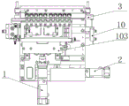
图1为本实用新型提出的一种用于从模具上分离镜片的自动取镜片装置的结构示意图;1 is a schematic structural diagram of an automatic lens-taking device for separating lenses from a mold proposed by the present utility model;
图2为本实用新型提出的一种用于从模具上分离镜片的自动取镜片装置的主视图;2 is a front view of an automatic lens-taking device for separating lenses from a mold proposed by the present utility model;
图3为本实用新型提出的一种用于从模具上分离镜片的自动取镜片装置的俯视图。FIG. 3 is a top view of an automatic lens-taking device for separating lenses from a mold according to the present invention.
图中:1、挤压驱动电机;101、滑板;102、第一支撑板;103、第二支撑板;2、平移驱动电机;3、上模托板;4、固定齿条;5、接上模漏斗;501、凹槽;6、移动齿条;7、取镜片吸盘;8、吸盘旋转驱动气缸;801、固定架;802、固定杆;9、吸盘升降驱动气缸;10、上模驱动气缸;11、固定座。In the figure: 1, extrusion drive motor; 101, slide plate; 102, first support plate; 103, second support plate; 2, translation drive motor; 3, upper die support plate; 4, fixed rack; 5, connection Upper mold funnel; 501, groove; 6, moving rack; 7, lens suction cup; 8, suction cup rotation drive cylinder; 801, fixed frame; 802, fixed rod; 9, suction cup lift drive cylinder; 10, upper mold drive Cylinder; 11. Fixed seat.
具体实施方式Detailed ways
下面将结合本实用新型实施例中的附图,对本实用新型实施例中的技术方案进行清楚、完整地描述,显然,所描述的实施例仅仅是本实用新型一部分实施例,而不是全部的实施例。The technical solutions in the embodiments of the present utility model will be clearly and completely described below with reference to the accompanying drawings in the embodiments of the present utility model. Obviously, the described embodiments are only a part of the embodiments of the present utility model, rather than all the implementations. example.
在本实用新型的描述中,需要理解的是,术语“上”、“下”、“前”、“后”、“左”、“右”、“顶”、“底”、“内”、“外”等指示的方位或位置关系为基于附图所示的方位或位置关系,仅是为了便于描述本实用新型和简化描述,而不是指示或暗示所指的装置或元件必须具有特定的方位、以特定的方位构造和操作,因此不能理解为对本实用新型的限制。In the description of the present invention, it should be understood that the terms "upper", "lower", "front", "rear", "left", "right", "top", "bottom", "inside", The orientation or positional relationship indicated by "outside" is based on the orientation or positional relationship shown in the accompanying drawings, which is only for the convenience of describing the present invention and simplifying the description, rather than indicating or implying that the indicated device or element must have a specific orientation , are constructed and operated in a specific orientation, and therefore should not be construed as a limitation of the present invention.
实施例:Example:
参照图1-3一种用于从模具上分离镜片的自动取镜片装置,包括固定座11,固定座11的顶部连接有平移驱动电机2,平移驱动电机2的输出端连接有第一支撑板102,第一支撑板102上连接有挤压驱动电机1,挤压驱动电机1的输出端连接有移动齿条6,固定座11的顶部还连接有与移动齿条6相配合的固定齿条4,且固定齿条4和移动齿条6之间连接有上模本体,固定座11的侧壁还连接有吸盘升降驱动气缸9,吸盘升降驱动气缸9的输出端连接有吸盘旋转驱动气缸8,吸盘旋转驱动气缸8的输出端连接有与上模本体相配合的取镜片吸盘7。Referring to FIGS. 1-3, an automatic lens-taking device for separating lenses from a mold includes a
固定座11内还连接有滑板101,第一支撑板102滑动连接在滑板101上。A
滑板101上设有滑槽,第一支撑板102滑动连接在滑槽内。The
滑板101的顶部外壁连接有上模驱动气缸10,上模驱动气缸10的输出端连接有上模托板3,上模本体连接在上模托板3上。The upper die
固定座11内设有凹槽501,凹槽501内连接有与上模本体相配合的接上模漏斗5。接上模漏斗5的顶部连接有漏嘴。The
挤压驱动电机1的输出端连接有第二支撑板103,移动齿条6连接在第二支撑板103的外壁。The output end of the extrusion drive motor 1 is connected with a
第二支撑板103滑动连接在第一支撑板102的外壁。The
吸盘旋转驱动气缸8的输出端连接有固定架801,固定架801上连接有固定杆802,取镜片吸盘7连接在固定杆802的外壁。The output end of the suction cup
固定座11的顶部外壁连接有挡板201,平移驱动电机2连接在挡板201内。A
固定座11的底部连接有固定板,固定板内开凿有螺纹孔。The bottom of the
本实用新型中,具体工作时,首先自动放置一排含有镜片的上模本体到上模托板3上,启动挤压驱动电机1,使其通过第二支撑板103带动移动齿条6向前移动,从而挤压上模本体,使其与固定齿条4相配合,固定齿条4和移动齿条6将上模本体挤压变形到一定程度后,启动平移驱动电机2,使其带动第一支撑板102移动,从而带动挤压驱动电机1和移动齿条6一起平移,上模本体则会在固定齿条4和移动齿条6之间旋转,旋转一圈后,平移驱动电机2驱动移动齿条6复位到初始位置,然后启动吸盘升降驱动气缸9,使其驱动吸盘旋转驱动气缸8和取镜片吸盘7一起下降,取镜片吸盘7吸取上模本体弧面上的隐形眼镜片,然后吸盘升降驱动气缸9上升到位后,吸盘旋转驱动气缸8驱动取镜片吸盘7旋转,将隐形眼镜片的凹口朝上,方便后续自动取料机构取放镜片,取镜片吸盘7吸取到隐形眼镜片后,上模驱动气缸10驱动上模托板3缩回,同时挤压驱动电机1驱动移动齿条6缩回,此时,取完镜片的上模本体会从上模托板3上落进凹槽501内,从而落入接上模漏斗5中,使其从接上模漏斗5底部的漏嘴流出,然后在接上模漏斗5的下方放置一个接上模本体的料盒即可收取废料。In the present utility model, during the specific operation, first, a row of upper mold bodies containing lenses is automatically placed on the upper
以上所述,仅为本实用新型较佳的具体实施方式,但本实用新型的保护范围并不局限于此,任何熟悉本技术领域的技术人员在本实用新型揭露的技术范围内,根据本实用新型的技术方案及其实用新型构思加以等同替换或改变,都应涵盖在本实用新型的保护范围之内。The above description is only a preferred embodiment of the present invention, but the protection scope of the present invention is not limited to this. Equivalent replacement or modification of the new technical solution and its utility model concept shall be included within the protection scope of the present utility model.
Claims (10)
Priority Applications (1)
| Application Number | Priority Date | Filing Date | Title |
|---|---|---|---|
| CN201921179986.8U CN210821014U (en) | 2019-07-25 | 2019-07-25 | Automatic lens taking device for separating lens from mold |
Applications Claiming Priority (1)
| Application Number | Priority Date | Filing Date | Title |
|---|---|---|---|
| CN201921179986.8U CN210821014U (en) | 2019-07-25 | 2019-07-25 | Automatic lens taking device for separating lens from mold |
Publications (1)
| Publication Number | Publication Date |
|---|---|
| CN210821014U true CN210821014U (en) | 2020-06-23 |
Family
ID=71278138
Family Applications (1)
| Application Number | Title | Priority Date | Filing Date |
|---|---|---|---|
| CN201921179986.8U Active CN210821014U (en) | 2019-07-25 | 2019-07-25 | Automatic lens taking device for separating lens from mold |
Country Status (1)
| Country | Link |
|---|---|
| CN (1) | CN210821014U (en) |
Cited By (1)
| Publication number | Priority date | Publication date | Assignee | Title |
|---|---|---|---|---|
| CN110356027A (en) * | 2019-07-25 | 2019-10-22 | 苏州茂特斯自动化设备有限公司 | An automatic lens taking device for separating lenses from molds |
-
2019
- 2019-07-25 CN CN201921179986.8U patent/CN210821014U/en active Active
Cited By (2)
| Publication number | Priority date | Publication date | Assignee | Title |
|---|---|---|---|---|
| CN110356027A (en) * | 2019-07-25 | 2019-10-22 | 苏州茂特斯自动化设备有限公司 | An automatic lens taking device for separating lenses from molds |
| CN110356027B (en) * | 2019-07-25 | 2025-01-21 | 苏州茂特斯自动化设备有限公司 | Automatic lens removal device for separating lenses from molds |
Similar Documents
| Publication | Publication Date | Title |
|---|---|---|
| CN211105761U (en) | Automatic contact lens machine is got in drawing of patterns | |
| CN116275768B (en) | Double-layer thermos bottle liner welding device and welding method thereof | |
| CN105195377B (en) | Full-automatic resin diamond point gum machine | |
| CN110696396B (en) | A contact lens demoulding integrated production equipment | |
| CN203991130U (en) | Full-automatic resin diamond point gum machine | |
| CN205043450U (en) | Fully automatic crown assembly equipment | |
| CN211105762U (en) | Contact lens compound die former | |
| CN115042471A (en) | But tablet production is with automatic collection's film clamp | |
| CN206327942U (en) | A kind of diaphragm automatic separating apparatus | |
| CN211594191U (en) | Feeding and discharging mechanism with function of continuously taking and placing materials in optical disk printer | |
| CN110356027B (en) | Automatic lens removal device for separating lenses from molds | |
| CN211031299U (en) | Automatic demolding and taking contact lens | |
| CN110356026B (en) | Automatic demoulding and contact lens removal equipment | |
| CN115091808A (en) | A catalyst tablet forming device and method | |
| CN115383977A (en) | Mold for processing anti-sticking automobile tail lamp plastic part and using method thereof | |
| CN121491194A (en) | A high-precision surface arc pressing method and system for metal car emblems | |
| CN219096028U (en) | Novel tablet press device for pharmaceutical engineering | |
| CN117086128B (en) | Aluminum extrusion machine | |
| CN219043627U (en) | Extrusion device for machining mechanical parts | |
| CN120756131B (en) | A precision positioning press for parts processing | |
| CN218224214U (en) | A precision finishing tool for processing of camera metal light ring base | |
| CN221697582U (en) | Flat vulcanizing machine with heating structure | |
| CN116810913B (en) | An air conditioning air guide plate processing device | |
| CN216175660U (en) | Water bowl punch forming mechanism | |
| CN110695060A (en) | Mobile phone flat steel sheet degumming recovery line |
Legal Events
| Date | Code | Title | Description |
|---|---|---|---|
| GR01 | Patent grant | ||
| GR01 | Patent grant | ||
| CP03 | Change of name, title or address | ||
| CP03 | Change of name, title or address |
Address after: No. 200 Gusu Road, Mudu Town, Wuzhong District, Suzhou City, Jiangsu Province 215000 Patentee after: Suzhou Maotesi Technology Co.,Ltd. Country or region after: China Address before: 215000 No.1 plant of buluode Science Park, 1328 Jinfeng South Road, Mudu Town, Wuzhong District, Suzhou City, Jiangsu Province Patentee before: SUZHOU MTSITY AUTOMATION EQUIPMENT Co.,Ltd. Country or region before: China |