CN210806903U - A new type of motor cooling base - Google Patents
A new type of motor cooling base Download PDFInfo
- Publication number
- CN210806903U CN210806903U CN201922263746.2U CN201922263746U CN210806903U CN 210806903 U CN210806903 U CN 210806903U CN 201922263746 U CN201922263746 U CN 201922263746U CN 210806903 U CN210806903 U CN 210806903U
- Authority
- CN
- China
- Prior art keywords
- motor
- rotating
- heat dissipation
- fixedly installed
- slot
- Prior art date
- Legal status (The legal status is an assumption and is not a legal conclusion. Google has not performed a legal analysis and makes no representation as to the accuracy of the status listed.)
- Expired - Fee Related
Links
Images


Landscapes
- Connection Of Motors, Electrical Generators, Mechanical Devices, And The Like (AREA)
Abstract
本实用新型提供一种新型电机散热底座,属于散热底座技术领域,该一种新型电机散热底座,包括底座主体,所述底座主体的顶部开设有放置槽,底座主体的顶部固定安装有电机放置座,放置槽的两侧内壁上固定安装有同一个防尘网,放置槽的底部内壁上开设有两个转动槽,两个转动槽内均转动安装有转动柱,转动柱的外侧固定安装有扇叶,放置槽的底部内壁上开设有电机槽,电机槽的底部内壁上固定安装有电机,电机的输出轴上固定套设有第一链轮,两个转动柱的外侧均固定套设有第二链轮。本实用新型结构简单,操作方便,能够快速方便的对电机放置座进行散热,同时,还能够对其进行防尘,散热效果好,所以满足了人们的需求。
The utility model provides a novel motor heat dissipation base, which belongs to the technical field of heat dissipation bases. The novel motor heat dissipation base comprises a base body, a placement groove is formed on the top of the base body, and a motor placement seat is fixedly installed on the top of the base body. , the same dustproof net is fixedly installed on the inner walls of both sides of the placement slot, and two rotating slots are opened on the inner wall of the bottom of the placement slot. The two rotating slots are rotatably installed with a rotating column, and the outer side of the rotating column is fixedly installed with a fan There is a motor slot on the inner wall of the bottom of the blade, the bottom inner wall of the motor slot is fixedly installed with a motor, the output shaft of the motor is fixedly sleeved with a first sprocket, and the outer sides of the two rotating columns are fixedly sleeved with a first sprocket. Two sprockets. The utility model has the advantages of simple structure and convenient operation, which can quickly and conveniently dissipate heat to the motor placement seat, and at the same time, it can also be dust-proof and has a good heat dissipation effect, thus meeting people's needs.
Description
技术领域technical field
本实用新型属于散热底座技术领域,具体涉及一种新型电机散热底座。The utility model belongs to the technical field of heat dissipation bases, in particular to a novel motor heat dissipation base.
背景技术Background technique
在现有技术中,随着现代机械技术的发展,电机在机械领域起着举足轻重的作用,许多的机械部件都需要使用到电机.现代的电机需要散热时,都在端盖的轴面上设置散热孔,然后从散热孔进行散热,但是端盖上的电机轴都会和外侧的物体连接,使散热孔被遮挡,使散热效果差。In the prior art, with the development of modern mechanical technology, the motor plays a pivotal role in the field of machinery, and many mechanical parts need to use the motor. When modern motors need to dissipate heat, they are all set on the axial surface of the end cover The heat dissipation hole is then used to dissipate heat from the heat dissipation hole, but the motor shaft on the end cover will be connected to the outside object, so that the heat dissipation hole is blocked and the heat dissipation effect is poor.
经过检索发现,在授权公告号为201721904072.4的中国专利中公开了一种具备散热功能的电机底座,涉及机电设备技术领域。该具备散热功能的电机底座,包括基座,基座底部的两侧均固定安装有支撑柱,支撑柱外部套设有减震筒,该具备散热功能的电机底座,通过水冷装置、水冷壳、卡块、水冷块、安装块、抽风机、吸气管、出风管、卡座、均风板、出气嘴和出气孔的配合,经过水冷块的冷却作用,水冷中的水被冷却,抽风机将外部的空气由吸气管吸入,由出风管排出,出风管中的空气经过冷水的冷却作用变为温度更低的冷风由出气嘴排出,冷风会对基座顶部的电机进行散热,该电机底座不仅具备放置电机的作用,还能对电机进行散热,相比传统的电机底座,适用性更好。After searching, it is found that a motor base with heat dissipation function is disclosed in the Chinese patent with the authorization announcement number of 201721904072.4, which relates to the technical field of electromechanical equipment. The motor base with heat dissipation function includes a base. Support columns are fixedly installed on both sides of the bottom of the base, and a shock-absorbing cylinder is sleeved on the outside of the support column. The combination of clamping block, water cooling block, installation block, exhaust fan, suction pipe, air outlet pipe, card seat, air equalizing plate, air outlet and air outlet, after the cooling effect of the water cooling block, the water in the water cooling is cooled, and the air is exhausted. The machine sucks the outside air through the suction pipe and discharges it from the air outlet pipe. The air in the air outlet pipe is cooled by the cold water into cold air with a lower temperature and is discharged from the air outlet. The cold air will dissipate the heat of the motor on the top of the base. , The motor base not only has the function of placing the motor, but also can dissipate the heat of the motor. Compared with the traditional motor base, the applicability is better.
但是上述技术方案由于使用水冷式散热,此种方式复杂繁琐,浪费人力物力,因此还存在操作不便,散热效果差的问题。However, the above technical solution uses water-cooled heat dissipation, which is complicated and cumbersome, wastes manpower and material resources, and thus has the problems of inconvenient operation and poor heat dissipation effect.
实用新型内容Utility model content
本实用新型的目的在于提供一种新型电机散热底座,旨在解决现有技术中的使用水冷式散热,此种方式复杂繁琐,浪费人力物力,因此还存在操作不便,散热效果差的的问题。The purpose of the present invention is to provide a new type of motor heat dissipation base, which aims to solve the problems of using water-cooled heat dissipation in the prior art, which is complicated and wastes manpower and material resources, so there are still problems of inconvenient operation and poor heat dissipation effect.
为实现上述目的,本实用新型提供如下技术方案:一种新型电机散热底座,包括底座主体,所述底座主体的顶部开设有放置槽,底座主体的顶部固定安装有电机放置座,放置槽的两侧内壁上固定安装有同一个防尘网,放置槽的底部内壁上开设有两个转动槽,两个转动槽内均转动安装有转动柱,转动柱的外侧固定安装有扇叶,放置槽的底部内壁上开设有电机槽,电机槽的底部内壁上固定安装有电机,电机的输出轴上固定套设有第一链轮,两个转动柱的外侧均固定套设有第二链轮,第一链轮的外侧啮合有链条,且第一链轮通过链条与两个第二链轮传动连接。In order to achieve the above purpose, the present invention provides the following technical solutions: a novel motor heat dissipation base, comprising a base body, a placement slot is opened on the top of the base body, a motor placement seat is fixedly installed on the top of the base body, and two parts of the placement slot are provided. The same dust-proof net is fixedly installed on the inner wall of the side, and two rotating grooves are opened on the inner wall of the bottom of the placing groove. A rotating column is rotatably installed in the two rotating grooves, and a fan blade is fixedly installed on the outer side of the rotating column. A motor slot is opened on the inner wall of the bottom, a motor is fixedly installed on the inner wall of the bottom of the motor slot, a first sprocket is fixedly sleeved on the output shaft of the motor, and a second sprocket is fixedly sleeved on the outer sides of the two rotating columns. The outer side of a sprocket is engaged with a chain, and the first sprocket is drivingly connected with the two second sprockets through the chain.
为了使得,作为本实用新型一种新型电机散热底座,优选的,所述底座主体的两侧均开设有散热口,两个散热口的底部内壁上均开设有安装槽,两个安装槽内均滑动安装有密封板,且两个密封板分别延伸至相对应的散热口内并与相对应的散热口的顶部内壁相接触,放置槽的两侧内壁上均开设有转动孔,两个转动孔与两个安装槽相连通。In order to make, as a new type of motor heat dissipation base of the present invention, preferably, both sides of the base body are provided with heat dissipation ports, the bottom inner walls of the two heat dissipation ports are provided with installation grooves, and the two installation grooves are provided with installation grooves. A sealing plate is slidably installed, and the two sealing plates extend into the corresponding heat dissipation ports respectively and are in contact with the top inner walls of the corresponding heat dissipation ports. The inner walls on both sides of the placement groove are provided with rotating holes, and the two rotating holes are connected to the inner wall of the corresponding heat dissipation port. The two mounting slots are connected.
为了使得,作为本实用新型一种新型电机散热底座,优选的,两个转动孔内均转动安装有转动杆,两个转动杆相互远离的一端分别延伸至相对应的安装槽内并固定安装有偏心轮,且两个密封板的底部分别与相对应的偏心轮相接触,安装槽的两侧内壁上均开设有滑槽。In order to make, as a new type of motor cooling base of the present invention, preferably, a rotating rod is rotatably installed in the two rotating holes, and the ends of the two rotating rods that are far away from each other respectively extend into the corresponding installation grooves and are fixedly installed with An eccentric wheel is provided, and the bottoms of the two sealing plates are respectively in contact with the corresponding eccentric wheel, and chute grooves are provided on the inner walls of both sides of the installation groove.
为了使得,作为本实用新型一种新型电机散热底座,优选的,所述密封板的两侧均固定安装有滑块,且两个滑块分别与相对应的滑槽滑动连接,两个滑块的底部均固定安装有复位弹簧,两个复位弹簧的底端分别与相对应的滑槽的底部内壁固定连接。In order to make, as a new type of motor cooling base of the present invention, preferably, sliders are fixedly installed on both sides of the sealing plate, and the two sliders are respectively slidably connected with the corresponding sliding grooves. A return spring is fixedly installed at the bottom of the two return springs, and the bottom ends of the two return springs are respectively fixedly connected with the bottom inner wall of the corresponding chute.
为了使得,作为本实用新型一种新型电机散热底座,优选的,两个转动柱的外侧均固定套设有第一轴锥形齿轮,两个转动杆相互靠近的一端均固定安装有第二锥形齿轮,且两个第二锥形齿轮分别与相对应的第一锥形齿轮相啮合。In order to make, as a new type of motor cooling base of the present invention, preferably, the outer sides of the two rotating columns are fixedly sleeved with a first shaft bevel gear, and the ends of the two rotating rods that are close to each other are fixedly installed with a second cone. The two second bevel gears are respectively meshed with the corresponding first bevel gears.
为了使得,作为本实用新型一种新型电机散热底座,优选的,所述扇叶的数量为三个,且三个扇叶呈环形等距离分布在转动柱上。In order to make, as a new type of motor cooling base of the present invention, preferably, the number of the fan blades is three, and the three fan blades are distributed on the rotating column in a ring shape at equal distances.
与现有技术相比,本实用新型的有益效果是:Compared with the prior art, the beneficial effects of the present utility model are:
1、使用中,启动电机,电机的输出轴带动第一链轮进行转动,第一链轮通过链条带动两个第二链轮进行转动,两个转动柱带动多个扇叶进行转动,多个扇叶对电机放置座进行散热;1. In use, start the motor, the output shaft of the motor drives the first sprocket to rotate, the first sprocket drives the two second sprockets to rotate through the chain, and the two rotating columns drive multiple fan blades to rotate. The fan blades dissipate heat to the motor placement seat;
2、同时,两个转动柱带动两个第一锥形齿轮进行转动,两个第一锥形齿轮带动两个第二锥形齿轮进行转动,使两个散热口打开,热气从散热口内排出,通过电机的不断转动,实现了对电机放置座的不断散热,电机关闭时,则密封板对散热口进行密封防尘;2. At the same time, the two rotating columns drive the two first bevel gears to rotate, and the two first bevel gears drive the two second bevel gears to rotate, so that the two heat dissipation ports are opened and the hot air is discharged from the heat dissipation ports. Through the continuous rotation of the motor, the continuous heat dissipation of the motor placement seat is realized. When the motor is turned off, the sealing plate seals and dustproofs the heat dissipation port;
本实用新型结构简单,操作方便,能够快速方便的对电机放置座进行散热,同时,还能够对其进行防尘,散热效果好,所以满足了人们的需求。The utility model has the advantages of simple structure and convenient operation, which can quickly and conveniently dissipate the heat of the motor placement seat, and at the same time, it can also be dust-proofed, and the heat dissipation effect is good, so the needs of people are met.
附图说明Description of drawings
附图用来提供对本实用新型的进一步理解,并且构成说明书的一部分,与本实用新型的实施例一起用于解释本实用新型,并不构成对本实用新型的限制。在附图中:The accompanying drawings are used to provide a further understanding of the present invention, and constitute a part of the specification, and are used to explain the present invention together with the embodiments of the present invention, and do not constitute a limitation to the present invention. In the attached image:
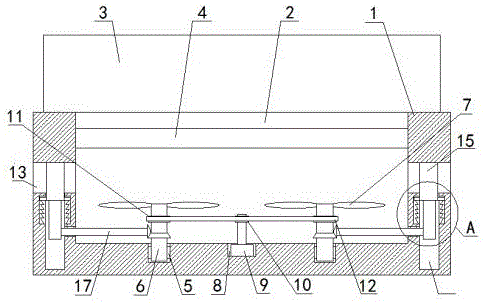
图1为本实用新型的主视结构示意图;Fig. 1 is the front view structure schematic diagram of the utility model;
图2为本实用新型中的A部分放大结构示意图;Fig. 2 is the enlarged structural representation of A part in the utility model;
图3为本实用新型中的局部侧视结构示意图。FIG. 3 is a partial side view structural schematic diagram of the utility model.
图中:1-底座主体;2-放置槽;3-电机放置座;4-防尘网;5-转动槽;6-转动柱;7-扇叶;8-电机槽;9-电机;10-第一链轮;11-第二链轮;12-链条;13-散热口;14-安装槽;15-密封板;16-转动孔;17-转动杆;18-偏心轮;19-滑槽;20-滑块;21-复位弹簧。In the figure: 1- base body; 2- placement slot; 3- motor placement seat; 4- dust filter; 5- rotating slot; 6- rotating column; 7- fan blade; 8- motor slot; 9- motor; 10 -1st sprocket; 11-second sprocket; 12-chain; 13-vent; 14-installation slot; 15-seal plate; 16-rotating hole; 17-rotating rod; 18-eccentric; 19-slide Slot; 20-slider; 21-return spring.
具体实施方式Detailed ways
下面将结合本实用新型实施例中的附图,对本实用新型实施例中的技术方案进行清楚、完整地描述,显然,所描述的实施例仅仅是本实用新型一部分实施例,而不是全部的实施例。基于本实用新型中的实施例,本领域普通技术人员在没有做出创造性劳动前提下所获得的所有其他实施例,都属于本实用新型保护的范围。The technical solutions in the embodiments of the present utility model will be clearly and completely described below with reference to the accompanying drawings in the embodiments of the present utility model. Obviously, the described embodiments are only a part of the embodiments of the present utility model, rather than all the implementations. example. Based on the embodiments of the present invention, all other embodiments obtained by those of ordinary skill in the art without creative work fall within the protection scope of the present invention.
实施例1Example 1
请参阅图1-3,本实用新型提供以下技术方案:一种新型电机散热底座,包括底座主体1,底座主体1的顶部开设有放置槽2,底座主体1的顶部固定安装有电机放置座3,放置槽2的两侧内壁上固定安装有同一个防尘网4,放置槽2的底部内壁上开设有两个转动槽5,两个转动槽5内均转动安装有转动柱6,转动柱6的外侧固定安装有扇叶7,放置槽2的底部内壁上开设有电机槽8,电机槽8的底部内壁上固定安装有电机9,电机9的输出轴上固定套设有第一链轮10,两个转动柱6的外侧均固定套设有第二链轮11,第一链轮10的外侧啮合有链条12,且第一链轮10通过链条12与两个第二链轮11传动连接。Please refer to FIGS. 1-3 , the present invention provides the following technical solutions: a novel motor cooling base, comprising a
在本实用新型的具体实施例中,第一链轮10通过链条12带动两个第二链轮11进行转动。In the specific embodiment of the present invention, the
具体的,底座主体1的两侧均开设有散热口13,两个散热口13的底部内壁上均开设有安装槽14,两个安装槽14内均滑动安装有密封板15,且两个密封板15分别延伸至相对应的散热口13内并与相对应的散热口13的顶部内壁相接触,放置槽2的两侧内壁上均开设有转动孔16,两个转动孔16与两个安装槽14相连通。Specifically, both sides of the
本实施例中:散热口13方便散热。In this embodiment, the
具体的,两个转动孔16内均转动安装有转动杆17,两个转动杆17相互远离的一端分别延伸至相对应的安装槽14内并固定安装有偏心轮18,且两个密封板15的底部分别与相对应的偏心轮18相接触,安装槽14的两侧内壁上均开设有滑槽19。Specifically, a rotating
本实施例中:偏心轮18的转动带动密封板15进行移动。In this embodiment, the rotation of the
具体的,密封板15的两侧均固定安装有滑块20,且两个滑块20分别与相对应的滑槽19滑动连接,两个滑块20的底部均固定安装有复位弹簧21,两个复位弹簧21的底端分别与相对应的滑槽19的底部内壁固定连接。Specifically, sliding
本实施例中:复位弹簧21起到限位和复位的作用。In this embodiment, the
具体的,两个转动柱6的外侧均固定套设有第一轴锥形齿轮,两个转动杆17相互靠近的一端均固定安装有第二锥形齿轮,且两个第二锥形齿轮分别与相对应的第一锥形齿轮相啮合。Specifically, the outer sides of the two
本实施例中:第一锥形齿轮和第二锥形齿轮改变转动的方向。In this embodiment, the first bevel gear and the second bevel gear change the direction of rotation.
具体的,扇叶7的数量为三个,且三个扇叶7呈环形等距离分布在转动柱6上。Specifically, the number of the
本实施例中:多个扇叶7使散热的效果更好。In this embodiment, the plurality of
本实用新型的工作原理及使用流程;使用中,启动电机9,电机9由控制开关进行控制,电机9由市电进行供电,电机9的输出轴带动第一链轮10进行转动,第一链轮10通过链条11带动两个第二链轮11进行转动,两个第二链轮11带动两个转动柱6进行转动,两个转动柱6带动多个扇叶7进行转动,多个扇叶7对电机放置座3进行散热,同时,两个转动柱6带动两个第一锥形齿轮进行转动,两个第一锥形齿轮带动两个第二锥形齿轮进行转动,两个第二锥形齿轮带动两个转动杆17进行转动,两个转动杆17带动两个偏心轮18进行转动,两个偏心轮18带动两个密封板15进行移动,两个密封板15带动两个滑块20进行移动,两个滑块20拉动两个复位弹簧21,两个复位弹簧21吸能,使两个散热口13打开,热气从散热口13内排出,通过电机9的不断转动,实现了对电机放置座3的不断散热,电机9关闭时,则密封板15对散热口13进行密封防尘,从而能够快速方便的对电机放置座3进行散热,同时,还能够对其进行防尘,散热效果好,所以满足了人们的需求。The working principle and use process of the utility model; in use, start the
最后应说明的是:以上所述仅为本实用新型的优选实施例而已,并不用于限制本实用新型,尽管参照前述实施例对本实用新型进行了详细的说明,对于本领域的技术人员来说,其依然可以对前述各实施例所记载的技术方案进行修改,或者对其中部分技术特征进行等同替换。凡在本实用新型的精神和原则之内,所作的任何修改、等同替换、改进等,均应包含在本实用新型的保护范围之内。Finally, it should be noted that the above are only the preferred embodiments of the present invention, and are not intended to limit the present invention. , it is still possible to modify the technical solutions described in the foregoing embodiments, or perform equivalent replacements to some of the technical features. Any modification, equivalent replacement, improvement, etc. made within the spirit and principle of the present invention shall be included in the protection scope of the present invention.
Claims (6)
Priority Applications (1)
| Application Number | Priority Date | Filing Date | Title |
|---|---|---|---|
| CN201922263746.2U CN210806903U (en) | 2019-12-17 | 2019-12-17 | A new type of motor cooling base |
Applications Claiming Priority (1)
| Application Number | Priority Date | Filing Date | Title |
|---|---|---|---|
| CN201922263746.2U CN210806903U (en) | 2019-12-17 | 2019-12-17 | A new type of motor cooling base |
Publications (1)
| Publication Number | Publication Date |
|---|---|
| CN210806903U true CN210806903U (en) | 2020-06-19 |
Family
ID=71232738
Family Applications (1)
| Application Number | Title | Priority Date | Filing Date |
|---|---|---|---|
| CN201922263746.2U Expired - Fee Related CN210806903U (en) | 2019-12-17 | 2019-12-17 | A new type of motor cooling base |
Country Status (1)
| Country | Link |
|---|---|
| CN (1) | CN210806903U (en) |
Cited By (1)
| Publication number | Priority date | Publication date | Assignee | Title |
|---|---|---|---|---|
| CN117394572A (en) * | 2023-10-20 | 2024-01-12 | 福建福清核电有限公司 | A motor base with cooling function |
-
2019
- 2019-12-17 CN CN201922263746.2U patent/CN210806903U/en not_active Expired - Fee Related
Cited By (2)
| Publication number | Priority date | Publication date | Assignee | Title |
|---|---|---|---|---|
| CN117394572A (en) * | 2023-10-20 | 2024-01-12 | 福建福清核电有限公司 | A motor base with cooling function |
| CN117394572B (en) * | 2023-10-20 | 2026-06-09 | 福建福清核电有限公司 | Motor base with cooling function |
Similar Documents
| Publication | Publication Date | Title |
|---|---|---|
| CN210806988U (en) | A motor structure with good ventilation effect | |
| CN211239532U (en) | Motor with quick heat dissipation mechanism | |
| CN108897388A (en) | A kind of computer cabinet | |
| CN209150855U (en) | A motor with a housing with a convenient installation function | |
| CN220121946U (en) | Heat abstractor of group battery subassembly | |
| CN219711903U (en) | Fan structure for air source heat pump | |
| CN210440234U (en) | Cooling water pump for new energy automobile | |
| CN119134781A (en) | A heat dissipation device for operation of a generator set | |
| CN205883775U (en) | Silencer double -end dibit electrical control cabinet for automatic welding machine | |
| CN116404555A (en) | Rescue device matched with power engineering construction | |
| CN213984390U (en) | Convection drying device for porcelain production | |
| CN114928194A (en) | Energy-saving three-phase asynchronous motor with higher protection capability | |
| CN116417920A (en) | A high-voltage switchgear with cleaning function | |
| CN211501051U (en) | A rotating base device and bladeless fan | |
| CN217838807U (en) | Preheating device for dry quenching treatment | |
| CN223435230U (en) | A confined space ventilation device | |
| CN222966796U (en) | Novel dust collector motor outer shell structure | |
| CN223152210U (en) | Gear drive high-speed structure | |
| CN214193044U (en) | A laser goggles cutting device | |
| CN221236997U (en) | Cooling device for hydraulic mechanical treatment | |
| CN222806727U (en) | A dry mill with ventilation and heat dissipation design | |
| CN211264149U (en) | A protection mechanism for an IoT controller | |
| CN221349615U (en) | A comprehensive drying device for fire-fighting castings | |
| CN213879561U (en) | Low-voltage motor protection device | |
| CN216218325U (en) | Distributed power saving device for electronic engineering |
Legal Events
| Date | Code | Title | Description |
|---|---|---|---|
| GR01 | Patent grant | ||
| GR01 | Patent grant | ||
| CF01 | Termination of patent right due to non-payment of annual fee | ||
| CF01 | Termination of patent right due to non-payment of annual fee |
Granted publication date: 20200619 |