CN210798825U - Advanced following drilling machine - Google Patents
Advanced following drilling machine Download PDFInfo
- Publication number
- CN210798825U CN210798825U CN201920896972.1U CN201920896972U CN210798825U CN 210798825 U CN210798825 U CN 210798825U CN 201920896972 U CN201920896972 U CN 201920896972U CN 210798825 U CN210798825 U CN 210798825U
- Authority
- CN
- China
- Prior art keywords
- driving wheel
- guide rail
- drilling rig
- chain
- lead
- Prior art date
- Legal status (The legal status is an assumption and is not a legal conclusion. Google has not performed a legal analysis and makes no representation as to the accuracy of the status listed.)
- Expired - Fee Related
Links
Images


Landscapes
- Earth Drilling (AREA)
Abstract
本实用新型公开了一种超前跟随钻机,包括起支撑作用的主梁和主导轨,还包括:安装在所述主导轨上表面并与所述导轨适配的托板;与所述托板的顶端连接的钻进装置;设置在所述主梁和主导轨之间的动力部;所述动力部通过活塞杆与主动轮总成连接;所述主动轮总成通过链条组件带动托板沿着所述主导轨的轴线方向作往复运动。本实用新型传动平稳,设计轻便,当进行煤层钻进时无卡顿,且安全可靠,可适用于圆周岩壁悬挂钻进。
The utility model discloses an advanced following drilling rig, which comprises a main beam and a main guide rail which play a supporting role, and further comprises: a support plate installed on the upper surface of the main guide rail and adapted to the guide rail; The drilling device connected at the top; the power part arranged between the main beam and the main guide rail; the power part is connected with the driving wheel assembly through the piston rod; the driving wheel assembly drives the pallet along the chain assembly through the chain assembly The axis direction of the main guide rail reciprocates. The utility model has the advantages of stable transmission, light design, no jamming during coal seam drilling, safety and reliability, and can be applied to the hanging drilling of the circumferential rock wall.
Description
技术领域technical field
本实用新型涉及矿山机械设备领域,具体的,涉及一种超前跟随钻机。The utility model relates to the field of mining machinery and equipment, in particular to a leading-following drilling rig.
背景技术Background technique
煤矿采煤工作面在回采过程中,瓦斯比较大,在煤炭的回采过程中会造成游离瓦斯会大量的涌出。而一部分吸附瓦斯也会变成游离瓦斯涌出。这样会造成瓦斯超限。给井下工作的人员带来生命的威胁。由于瓦斯大量附存在煤层中,并有一定的压力,加上煤碳在回采的过程中,回采后采空区会随工作面向前推进老顶出现垮落形成压力的重新分布,(既我们常说的矿压),常常会造成煤于瓦斯的突出。同样也给井下的工作人员带来生命的威胁。为了解决以上二个问题,煤矿现在常采用的是浅孔抽放瓦斯技术,即:在煤层内打深20~30米的孔进行缷压和瓦斯抽放。做到提前释放瓦斯和煤层压力。传统钻机采用的是架式,整体采取的都是钢材制作的组件。靠圆导轨或者板式导轨与滑块组件连接,靠油缸伸缩,滑块组件滑动来拖动动力头或夹持器在机架上移动。存在以下缺点:During the mining process of coal mining face, the gas is relatively large, which will cause a large amount of free gas to flow out during the coal mining process. Part of the adsorbed gas will also turn into free gas and flow out. This will cause the gas to exceed the limit. Threats to the lives of people working underground. Since a large amount of gas is attached to the coal seam and has a certain pressure, and in the process of coal mining, the goaf will redistribute as the working face advances and the old roof will collapse to form pressure redistribution (that is, we often said mine pressure), which often results in the outburst of coal and gas. It also threatens the lives of the underground workers. In order to solve the above two problems, coal mines often use shallow-hole gas drainage technology, that is, drilling
1.滑轨或滑道容易变形;1. The slide rail or slideway is easy to deform;
2.滑动时不平稳,有时卡顿,声响大;2. The sliding is not stable, sometimes stuck, and the sound is loud;
3.整体偏重,不宜用于悬挂或绕固定轴线旋转的轨道;3. The overall weight is heavy, and it is not suitable for suspension or orbits that rotate around a fixed axis;
4.液压或手动夹持器结构和操作较为复杂,存在安全隐患。4. The structure and operation of the hydraulic or manual gripper are more complicated, and there are potential safety hazards.
实用新型内容Utility model content
有鉴于此,本实用新型的目的是提供一种超前跟随钻机,优点是轻型、导向性好、夹持器安全可靠并简单、平稳传动、小噪音、安全可靠。In view of this, the purpose of the present utility model is to provide an advance following drilling rig, which has the advantages of light weight, good guidance, safe, reliable and simple gripper, smooth transmission, low noise, and safety and reliability.
本实用新型的目的是通过以下技术方案实现的:The purpose of this utility model is to realize through the following technical solutions:
一种超前跟随钻机,包括主梁和主导轨,还包括:A lead-following drilling rig, comprising a main beam and a main guide rail, and further comprising:
安装在所述主导轨上表面并与所述主导轨适配的托板;a pallet mounted on the upper surface of the main guide rail and adapted to the main guide rail;
与所述托板的顶端连接的钻进装置;a drilling device connected to the top end of the pallet;
设置在所述主梁和主导轨之间的动力部;a power part arranged between the main beam and the main guide rail;
所述动力部通过活塞杆与主动轮总成连接;The power part is connected with the driving wheel assembly through the piston rod;
所述主动轮总成通过链条组件带动托板沿着所述主导轨的轴线方向作往复运动。The driving wheel assembly drives the pallet to reciprocate along the axis direction of the main guide rail through the chain assembly.
进一步,所述主动轮总成包括与所述活塞杆连接的连接体以及设置在连接体上的第一主动轮和第二主动轮。Further, the driving wheel assembly includes a connecting body connected with the piston rod, and a first driving wheel and a second driving wheel arranged on the connecting body.
进一步,所述链条组件包括第一链条和第二链条,所述第一链条远离所述主滚轮总成的一端与托板的一端活动连接,所述第二链条远离所述主滚轮总成的一端与所述托板的另一端活动连接。Further, the chain assembly includes a first chain and a second chain, one end of the first chain away from the main roller assembly is movably connected with one end of the support plate, and the second chain is away from the main roller assembly One end is movably connected with the other end of the support plate.
进一步,所述主梁靠近所述第一主动轮的一端设置与所述第一主动轮配合滚动的第一从动轮。Further, the end of the main beam close to the first driving wheel is provided with a first driven wheel that cooperates with the first driving wheel to roll.
进一步,所述主梁靠近所述第二主动轮的一端设置与所述第二主动轮配合滚动的第二从动轮。Further, the end of the main beam close to the second driving wheel is provided with a second driven wheel that cooperates with the second driving wheel to roll.
进一步,还包括设置在所述主梁和主导轨之间,用于限制所述主动轮总成滑动方向的副导轨。Further, it also includes an auxiliary guide rail disposed between the main beam and the main guide rail for restricting the sliding direction of the driving wheel assembly.
进一步,所述钻进装置包括依次连接的马达、动力头、水辫总成和钻杆,所述钻杆通过夹持器固定在所述主梁的上表面。Further, the drilling device includes a motor, a power head, a water braid assembly and a drill pipe which are connected in sequence, and the drill pipe is fixed on the upper surface of the main beam by a holder.
进一步,所述链条组件通过链条座与所述托板连接。Further, the chain assembly is connected with the support plate through a chain seat.
进一步,所述第一从动轮的数量至少为1个。Further, the number of the first driven wheel is at least one.
进一步,所述第二从动轮的数量至少为1个。Further, the number of the second driven wheel is at least one.
本实用新型的有益效果是:The beneficial effects of the present utility model are:
本实用新型传动平稳,设计轻便,当进行煤层钻进时无卡顿,且安全可靠,可适用于圆周岩壁悬挂钻进。The utility model has the advantages of stable transmission, light design, no jamming during coal seam drilling, safety and reliability, and can be applied to the hanging drilling of the circumferential rock wall.
本实用新型的其他优点、目标和特征在某种程度上将在随后的说明书中进行阐述,并且在某种程度上,基于对下文的考察研究对本领域技术人员而言将是显而易见的,或者可以从本实用新型的实践中得到教导。本实用新型的目标和其他优点可以通过下面的说明书和权利要求书来实现和获得。Other advantages, objects and features of the present invention will be set forth in the description that follows, and to the extent that will be apparent to those skilled in the art based on a study of the following, or may be Lessons are learned from the practice of the present invention. The objectives and other advantages of the present invention may be realized and attained by the following description and claims.
附图说明Description of drawings
为了使本实用新型的目的、技术方案和优点更加清楚,下面将结合附图对本实用新型作进一步的详细描述,其中:In order to make the purpose, technical solutions and advantages of the present utility model clearer, the present utility model will be described in further detail below in conjunction with the accompanying drawings, wherein:
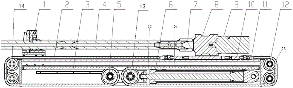
附图1为本实用新型全剖内部视图;Accompanying drawing 1 is the full-section internal view of the utility model;
附图2为本实用新型外形三维视图;Accompanying drawing 2 is the three-dimensional view of the utility model appearance;
附图3为本实用新型的夹持器结构实体图;Accompanying
附图4为本实用新型传动示意图。Accompanying
具体实施方式Detailed ways
以下将参照附图,对本实用新型的优选实施例进行详细的描述。应当理解,优选实施例仅为了说明本实用新型,而不是为了限制本实用新型的保护范围。The preferred embodiments of the present invention will be described in detail below with reference to the accompanying drawings. It should be understood that the preferred embodiments are only for illustrating the present invention, rather than for limiting the protection scope of the present invention.
本实用新型提出了一种超前跟随钻机,如图1和2所示,一种超前跟随钻机包括主梁16和主导轨15,还包括:The utility model proposes an advanced following drilling rig. As shown in Figures 1 and 2, an advanced following drilling rig includes a
安装在主导轨15的上表面并与主导轨适配的托板10;与托板10的顶端连接的钻进装置;设置在主梁16和主导轨15之间的动力部6;动力部6通过活塞杆21与主动轮总成连接。主动轮总成包括与活塞杆21连接的连接体22以及设置在连接体22上的第一主动轮5和第二主动轮13。本实施例的动力部6为气压缸,主导轨15采用不锈钢耐磨材料制成。The
作为进一步改进,第一链条2远离主滚轮总成的一端与托板10的前端活动连接,第二链条23远离主滚轮总成的一端与托板10的后端活动连接。主梁16靠近第一主动轮5的一端设置与第一主动轮5配合滚动的第一从动轮14,主梁16靠近第二主动轮13的一端设置与第二主动轮13配合滚动的第二从动轮12。还包括设置在主梁16和主导轨15之间,用于限制主动轮总成滑动方向的副导轨3。本实施例中第一从动轮14和第二从动轮12的数量均为2个,且均为竖直方向分布。本实施例通过第一主动轮5、第二主动轮13、第一从动轮14和第二从动轮12位置及数量的合理设计,使得托板10的移动距离是活塞杆21移动距离的2倍。链条组件通过链条座11与托板10连接。As a further improvement, one end of the first chain 2 away from the main roller assembly is movably connected to the front end of the
作为进一步改进,钻进装置包括依次连接的马达9、动力头8、水辫总成7和钻杆4,钻杆4通过夹持器1固定在主梁16的上表面。如图3所示,夹持器1的气缸总成17的活塞杆伸出,带动滑动板18在滑槽19内上下滑动,往下卡到钻杆4的四方上,当马达9反转时,即可拆卸钻杆4。As a further improvement, the drilling device includes a
本实用新型的实施方式是:如图4所示,需要调整钻杆4前后对接位置时,动力部6的活塞杆伸出,主动滚轮总成往前沿着滑座导轨3移动,第一主动轮5逆时针旋转,通过第一链条2带动第一从动轮14顺时针运动,进而使得托板10的前端向前运动,第二主动轮13顺时针旋转,通过第二链条23带动第二从动轮12逆时针运动,进而使得的托板10后端向前运动;动力部6的活塞杆缩回,主动滚轮总成往后沿着滑座导轨3移动,第一主动轮5顺时针旋转,通过第一链条2带动第一从动轮14逆时针运动,进而使得托板10的前端向后运动,第二主动轮13逆时针旋转,通过第二链条23带动第二从动轮12顺时针运动,进而使得的托板10后端向后运动。马达9正转时,由动力头8提供钻进动力,水辫总成7提供钻进液体,实施湿式破岩,马达9反转时,控制钻杆4前后距离,让夹持器1工作,拆卸钻杆。The embodiment of the present invention is as follows: as shown in FIG. 4 , when the front and rear docking positions of the
最后说明的是,以上实施例仅用以说明本实用新型的技术方案而非限制,尽管参照较佳实施例对本实用新型进行了详细说明,本领域的普通技术人员应当理解,可以对本实用新型的技术方案进行修改或者等同替换,而不脱离本技术方案的宗旨和范围,其均应涵盖在本实用新型的权利要求范围当中。Finally, it should be noted that the above embodiments are only used to illustrate the technical solutions of the present invention and not to limit them. Although the present invention has been described in detail with reference to the preferred embodiments, those of ordinary skill in the art should The technical solutions are modified or equivalently replaced without departing from the purpose and scope of the technical solutions, and they should all be included in the scope of the claims of the present invention.
Claims (10)
Priority Applications (1)
| Application Number | Priority Date | Filing Date | Title |
|---|---|---|---|
| CN201920896972.1U CN210798825U (en) | 2019-06-14 | 2019-06-14 | Advanced following drilling machine |
Applications Claiming Priority (1)
| Application Number | Priority Date | Filing Date | Title |
|---|---|---|---|
| CN201920896972.1U CN210798825U (en) | 2019-06-14 | 2019-06-14 | Advanced following drilling machine |
Publications (1)
| Publication Number | Publication Date |
|---|---|
| CN210798825U true CN210798825U (en) | 2020-06-19 |
Family
ID=71229168
Family Applications (1)
| Application Number | Title | Priority Date | Filing Date |
|---|---|---|---|
| CN201920896972.1U Expired - Fee Related CN210798825U (en) | 2019-06-14 | 2019-06-14 | Advanced following drilling machine |
Country Status (1)
| Country | Link |
|---|---|
| CN (1) | CN210798825U (en) |
Cited By (1)
| Publication number | Priority date | Publication date | Assignee | Title |
|---|---|---|---|---|
| CN115492529A (en) * | 2022-09-08 | 2022-12-20 | 无锡锡钻地质装备有限公司 | Drilling machine body assembly |
-
2019
- 2019-06-14 CN CN201920896972.1U patent/CN210798825U/en not_active Expired - Fee Related
Cited By (1)
| Publication number | Priority date | Publication date | Assignee | Title |
|---|---|---|---|---|
| CN115492529A (en) * | 2022-09-08 | 2022-12-20 | 无锡锡钻地质装备有限公司 | Drilling machine body assembly |
Similar Documents
| Publication | Publication Date | Title |
|---|---|---|
| CN104612586B (en) | Tunneling boring rapid drilling drill carriage for the big emptying aperture parallel cut blasting in tunnel | |
| US11384638B2 (en) | Apparatus for controllably unfolding flexible mesh for continuous miner, and continuous miner | |
| CN105822225B (en) | A kind of two Drilling rock jib structure of an arm | |
| CN102900362A (en) | Narrow-machine-body full-hydraulic bolt and anchor cable drill carriage for coal mine tunnel | |
| CN101509350A (en) | Pneumatic crawler hydraulic jumbo | |
| CN112443278B (en) | Perforating machine for underground hydraulic operation of coal mine | |
| CN108505938B (en) | A rope pulley stroke amplification airborne drilling rig | |
| CN108678666B (en) | A multifunctional drilling rig and pipe shed installation device | |
| CN111520539B (en) | Device for jacking construction of pipeline | |
| CN205743712U (en) | A kind of pneumatic frame column type vibrodrill | |
| CN109026098B (en) | Hydraulic anchor withdrawing vehicle | |
| CN204371098U (en) | A kind of Combined hydraulic jump bit rig | |
| CN107217988B (en) | A high-pressure hydraulic seam cutting machine for coal mine excavation face | |
| CN201354588Y (en) | Pneumatic tracked hydraulic jumbo | |
| CN213627518U (en) | Portable coal seam water injection hole packer | |
| CN107461194B (en) | Cantilevered longitudinal axis development machine | |
| CN106677714A (en) | Roof bolter and method of use thereof | |
| CN210289629U (en) | Perforating machine for coal mine underground water power industry | |
| CN204357347U (en) | A kind of new type mining drilling apparatus | |
| CN221879301U (en) | Angle-adjustable directional drilling machine for coal mines | |
| CN105386721B (en) | a drilling rig | |
| CN104632071A (en) | Coal mine gas-liquid linkage drilling rig | |
| CN204476261U (en) | A kind of all-hydraulic normotopia jumbo | |
| CN206468895U (en) | A kind of conduit jacking | |
| CN119218925A (en) | A crawler type emulsion lifting platform for coal mining working face in coal mine |
Legal Events
| Date | Code | Title | Description |
|---|---|---|---|
| GR01 | Patent grant | ||
| GR01 | Patent grant | ||
| CF01 | Termination of patent right due to non-payment of annual fee | ||
| CF01 | Termination of patent right due to non-payment of annual fee |
Granted publication date: 20200619 |