CN210794820U - Mobile robot scheduling device - Google Patents
Mobile robot scheduling device Download PDFInfo
- Publication number
- CN210794820U CN210794820U CN201921933755.1U CN201921933755U CN210794820U CN 210794820 U CN210794820 U CN 210794820U CN 201921933755 U CN201921933755 U CN 201921933755U CN 210794820 U CN210794820 U CN 210794820U
- Authority
- CN
- China
- Prior art keywords
- mobile robot
- fixed
- bevel gear
- drive box
- support plate
- Prior art date
- Legal status (The legal status is an assumption and is not a legal conclusion. Google has not performed a legal analysis and makes no representation as to the accuracy of the status listed.)
- Expired - Fee Related
Links
- 230000005540 biological transmission Effects 0.000 claims abstract description 10
- 230000008878 coupling Effects 0.000 claims abstract description 4
- 238000010168 coupling process Methods 0.000 claims abstract description 4
- 238000005859 coupling reaction Methods 0.000 claims abstract description 4
- 239000003921 oil Substances 0.000 claims description 6
- 239000010720 hydraulic oil Substances 0.000 claims description 4
- 238000004891 communication Methods 0.000 claims description 3
- 230000017525 heat dissipation Effects 0.000 claims description 3
- 239000012530 fluid Substances 0.000 claims description 2
- 238000010586 diagram Methods 0.000 description 4
- 238000001816 cooling Methods 0.000 description 2
- 238000013473 artificial intelligence Methods 0.000 description 1
- 230000009286 beneficial effect Effects 0.000 description 1
- 238000010276 construction Methods 0.000 description 1
- 238000005516 engineering process Methods 0.000 description 1
- 238000004519 manufacturing process Methods 0.000 description 1
- 238000000034 method Methods 0.000 description 1
Images


Landscapes
- Manipulator (AREA)
Abstract
本实用新型公开了一种移动机器人调度装置,包括移动机器人本体、驱动箱和支撑板,所述移动机器人本体上表面中间嵌入固定有液压缸,所述液压缸顶端活动安装有液压杆,所述液压杆顶端与驱动箱下表面中间固定连接,所述驱动箱内部一侧通过底座固定有步进电机,所述步进电机一端通过联轴器转动安装有传动轴,所述传动轴背离步进电机的一端固定有第一锥齿轮,所述驱动箱顶端中间通过轴承转动安装有支柱,所述支柱底端位于驱动箱内,所述支柱底端固定有第二锥齿轮,所述第二锥齿轮与第一锥齿轮啮合连接,所述支柱顶端伸出驱动箱,所述支柱顶端与支撑板下表面中间固定连接。本实用新型具有对放置货物的支撑板角度调节,便于调节货物角度的优点。
The utility model discloses a mobile robot dispatching device, comprising a mobile robot body, a driving box and a support plate. A hydraulic cylinder is embedded and fixed in the middle of the upper surface of the mobile robot body, and a hydraulic rod is movably installed at the top of the hydraulic cylinder. The top of the hydraulic rod is fixedly connected with the lower surface of the drive box. A stepping motor is fixed on one side of the drive box through the base. One end of the stepping motor is rotated and installed with a transmission shaft through a coupling, and the transmission shaft is away from the stepping motor. One end of the motor is fixed with a first bevel gear, a support is rotatably installed in the middle of the top end of the drive box through a bearing, the bottom end of the support is located in the drive box, and a second bevel gear is fixed at the bottom end of the support, and the second bevel gear is fixed at the bottom end of the support. The gear is meshed and connected with the first bevel gear, the top end of the strut extends out of the drive box, and the top end of the strut is fixedly connected to the middle of the lower surface of the support plate. The utility model has the advantages of adjusting the angle of the support plate on which the goods are placed, so as to facilitate the adjustment of the angle of the goods.
Description
技术领域technical field
本实用新型涉及移动机器人技术领域,具体为一种移动机器人调度装置。The utility model relates to the technical field of mobile robots, in particular to a mobile robot scheduling device.
背景技术Background technique
移动机器人是自动执行工作的机器装置。它既可以接受人类指挥,又可以运行预先编排的程序,也可以根据以人工智能技术制定的原则纲领行动。它的任务是协助或取代人类工作的工作,例如生产业、建筑业,或是危险的工作。Mobile robots are mechanical devices that perform work automatically. It can accept human command, run pre-programmed programs, or act according to principles and programs formulated with artificial intelligence technology. Its task is to assist or replace human jobs, such as production, construction, or dangerous jobs.
移动机器人是由一套完整的驱动机构执行机器人的移动,可实现自动行走。移动机器人多用于搬运货物,一般的移动机器人在搬运货物时,只能移开底部的地轮实现转向,在一些地方依靠地轮转向不方便,不能准确的调整货物的角度。The mobile robot is a complete set of driving mechanism to execute the movement of the robot, which can realize automatic walking. Mobile robots are mostly used to carry goods. When carrying goods, general mobile robots can only remove the ground wheel at the bottom to achieve steering. In some places, it is inconvenient to rely on the ground wheel to turn, and the angle of the goods cannot be adjusted accurately.
实用新型内容Utility model content
本实用新型的目的在于提供一种移动机器人调度装置,具备通过对放置货物的支撑板角度调节,便于调节货物角度的优点,解决了移动机器人在搬运货物时,只能移开底部的地轮实现转向,在一些地方依靠地轮转向不方便,不能准确的调整货物的角度的问题。The purpose of the present utility model is to provide a mobile robot dispatching device, which has the advantage of adjusting the angle of the support plate on which the goods are placed, which facilitates the adjustment of the angle of the goods, and solves the problem that the mobile robot can only remove the ground wheel at the bottom when carrying the goods. Steering, relying on the ground wheel to turn in some places is inconvenient, and the angle of the cargo cannot be adjusted accurately.
为实现上述目的,本实用新型提供如下技术方案:一种移动机器人调度装置,包括移动机器人本体、驱动箱和支撑板,所述移动机器人本体上表面中间嵌入固定有液压缸,所述液压缸顶端活动安装有液压杆,所述液压杆顶端与驱动箱下表面中间固定连接,所述驱动箱内部一侧通过底座固定有步进电机,所述步进电机一端通过联轴器转动安装有传动轴,所述传动轴背离步进电机的一端固定有第一锥齿轮,所述驱动箱顶端中间通过轴承转动安装有支柱,所述支柱底端位于驱动箱内,所述支柱底端固定有第二锥齿轮,所述第二锥齿轮与第一锥齿轮啮合连接,所述支柱顶端伸出驱动箱,所述支柱顶端与支撑板下表面中间固定连接。In order to achieve the above purpose, the present utility model provides the following technical solutions: a mobile robot scheduling device, comprising a mobile robot body, a drive box and a support plate, a hydraulic cylinder is embedded and fixed in the middle of the upper surface of the mobile robot body, and the top of the hydraulic cylinder is fixed. A hydraulic rod is movably installed, and the top of the hydraulic rod is fixedly connected to the lower surface of the drive box. A stepping motor is fixed on one side of the drive box through the base, and a transmission shaft is rotated and installed on one end of the stepping motor through a coupling. A first bevel gear is fixed at the end of the transmission shaft facing away from the stepping motor, a pillar is rotatably installed in the middle of the top of the driving box through a bearing, the bottom end of the pillar is located in the driving box, and the bottom end of the pillar is fixed with a second bevel gear. A bevel gear, the second bevel gear is meshed with the first bevel gear, the top end of the strut extends out of the drive box, and the top end of the strut is fixedly connected to the middle of the lower surface of the support plate.
优选的,所述移动机器人本体下表面四角处均转动安装有地轮。Preferably, ground wheels are rotatably installed at four corners of the lower surface of the mobile robot body.
优选的,所述液压缸内配有液压泵和油箱,液压泵、油箱和液压缸之间通过液压油管流体连通。Preferably, the hydraulic cylinder is provided with a hydraulic pump and an oil tank, and the hydraulic pump, the oil tank and the hydraulic cylinder are in fluid communication through a hydraulic oil pipe.
优选的,所述轴承嵌入安装在驱动箱顶端中间,轴承分为内环和外环,内环和外环之间通过滚珠转动连接,内环与支柱固定,外环与驱动箱顶端固定。Preferably, the bearing is embedded and installed in the middle of the top of the drive box, the bearing is divided into an inner ring and an outer ring, the inner ring and the outer ring are connected by ball rotation, the inner ring is fixed to the strut, and the outer ring is fixed to the top of the drive box.
优选的,所述驱动箱正面开设有散热孔。Preferably, the front side of the drive box is provided with cooling holes.
优选的,所述支撑板上表面四角处均固定有橡胶垫。Preferably, rubber pads are fixed at the four corners of the upper surface of the support plate.
与现有技术相比,本实用新型的有益效果如下:本实用新型通过设置驱动箱、第一锥齿轮、第二锥齿轮、支柱和支撑板,达到了通过对放置货物的支撑板角度调节,便于调节货物角度的效果,本实用新型设置有驱动箱、第一锥齿轮、第二锥齿轮、支柱和支撑板,驱动箱通过液压缸和液压杆与移动机器人本体活动连接,驱动箱内部固定有步进电机,步进电机与移动机器人本体内的控制模块电连接,步进电机一端通过传动轴带动第一锥齿轮转动,第一锥齿轮与第二锥齿轮啮合连接,第二锥齿轮固定有支柱,支柱顶端穿过驱动箱顶端与支撑板下表面固定,支柱与驱动箱顶端连接处固定有轴承。货物放置在支撑板上,橡胶垫与货物接触,加大摩擦力,调整货物的角度时,启动步进电机,步进电机带动第一锥齿轮转动,第一锥齿轮带动第二锥齿轮转动,支柱转动带动支撑板转动,从而调节支撑板上的货物的角度。Compared with the prior art, the beneficial effects of the present utility model are as follows: the present utility model achieves the adjustment of the angle of the supporting plate on which the goods are placed by arranging the drive box, the first bevel gear, the second bevel gear, the strut and the support plate, The utility model is provided with a drive box, a first bevel gear, a second bevel gear, a pillar and a support plate to facilitate the adjustment of the angle of the cargo. The drive box is movably connected with the mobile robot body through a hydraulic cylinder and a hydraulic rod. The inside of the drive box is fixed with Stepper motor, the stepper motor is electrically connected with the control module in the mobile robot body, one end of the stepper motor drives the first bevel gear to rotate through the transmission shaft, the first bevel gear is meshed with the second bevel gear, and the second bevel gear is fixed with The pillar, the top of the pillar passes through the top of the driving box and is fixed to the lower surface of the support plate, and a bearing is fixed at the connection between the pillar and the top of the driving box. The goods are placed on the support plate, the rubber pad is in contact with the goods, and the friction force is increased. When the angle of the goods is adjusted, the stepper motor is started, and the stepper motor drives the first bevel gear to rotate, and the first bevel gear drives the second bevel gear to rotate. The rotation of the pillar drives the rotation of the support plate, thereby adjusting the angle of the goods on the support plate.
附图说明Description of drawings
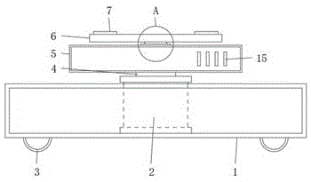
图1为本实用新型的主视结构示意图;Fig. 1 is the front view structure schematic diagram of the utility model;
图2为本实用新型的A处放大示意图;Fig. 2 is the enlarged schematic diagram of A place of the present utility model;
图3为本实用新型的俯视结构示意图;Fig. 3 is the top view structure schematic diagram of the utility model;
图4为本实用新型的驱动箱内部连接结构示意图。4 is a schematic diagram of the internal connection structure of the drive box of the present invention.
图中:1、移动机器人本体;2、液压缸;3、地轮;4、液压杆;5、驱动箱;6、支撑板;7、橡胶垫;8、轴承;9、支柱;10、底座;11、步进电机;12、传动轴;13、第一锥齿轮;14、第二锥齿轮;15、散热孔。In the figure: 1. Mobile robot body; 2. Hydraulic cylinder; 3. Ground wheel; 4. Hydraulic rod; 5. Drive box; 6. Support plate; 7. Rubber pad; 8. Bearing; 9. Pillar; 10. Base ; 11, stepping motor; 12, transmission shaft; 13, first bevel gear; 14, second bevel gear; 15, cooling hole.
具体实施方式Detailed ways
下面将结合本实用新型实施例中的附图,对本实用新型实施例中的技术方案进行清楚、完整地描述,显然,所描述的实施例仅仅是本实用新型一部分实施例,而不是全部的实施例。基于本实用新型中的实施例,本领域普通技术人员在没有做出创造性劳动前提下所获得的所有其他实施例,都属于本实用新型保护的范围。The technical solutions in the embodiments of the present utility model will be clearly and completely described below with reference to the accompanying drawings in the embodiments of the present utility model. Obviously, the described embodiments are only a part of the embodiments of the present utility model, rather than all the implementations. example. Based on the embodiments of the present invention, all other embodiments obtained by those of ordinary skill in the art without creative work fall within the protection scope of the present invention.
在本实用新型的描述中,需要说明的是,术语“上”、“下”、“内”、“外”“前端”、“后端”、“两端”、“一端”、“另一端”等指示的方位或位置关系为基于附图所示的方位或位置关系,仅是为了便于描述本实用新型和简化描述,而不是指示或暗示所指的装置或元件必须具有特定的方位、以特定的方位构造和操作,因此不能理解为对本实用新型的限制。此外,术语“第一”、“第二”仅用于描述目的,而不能理解为指示或暗示相对重要性。In the description of the present invention, it should be noted that the terms "upper", "lower", "inner", "outer", "front end", "rear end", "two ends", "one end", "the other end" The orientation or positional relationship indicated by "" etc. is based on the orientation or positional relationship shown in the accompanying drawings, and is only for the convenience of describing the present invention and simplifying the description, rather than indicating or implying that the indicated device or element must have a specific orientation, so as to The specific orientation configuration and operation is therefore not to be construed as a limitation of the present invention. Furthermore, the terms "first" and "second" are used for descriptive purposes only and should not be construed to indicate or imply relative importance.
在本实用新型的描述中,需要说明的是,除非另有明确的规定和限定,术语“安装”、“设置有”、“连接”等,应做广义理解,例如“连接”,可以是固定连接,也可以是可拆卸连接,或一体地连接;可以是机械连接,也可以是电连接;可以是直接相连,也可以通过中间媒介间接相连,可以是两个元件内部的连通。对于本领域的普通技术人员而言,可以具体情况理解上述术语在本实用新型中的具体含义。In the description of the present utility model, it should be noted that, unless otherwise expressly specified and limited, the terms "installed", "provided with", "connected", etc., should be understood in a broad sense, for example, "connected" may be a fixed The connection can also be a detachable connection, or an integral connection; it can be a mechanical connection or an electrical connection; it can be a direct connection, or an indirect connection through an intermediate medium, and it can be internal communication between two components. For those of ordinary skill in the art, the specific meanings of the above terms in the present invention can be understood in specific situations.
请参阅图1至图4,本实用新型提供的一种实施例:一种移动机器人调度装置,包括移动机器人本体1、驱动箱5和支撑板6,移动机器人本体1下表面四角处均转动安装有地轮3,地轮3与移动机器人本体1内部的驱动机构连接,每个地轮3配有单独的驱动马达,通过齿轮的啮合连接实现地轮3的转动。移动机器人本体1内置有电源。Please refer to FIGS. 1 to 4 , an embodiment provided by the present invention: a mobile robot dispatching device, comprising a
移动机器人本体1上表面中间嵌入固定有液压缸2,液压缸2内配有液压泵和油箱,液压泵、油箱和液压缸2之间通过液压油管流体连通,液压泵采用CB-FC32型号,液压泵与移动机器人本体1内的控制模块电连接。液压缸2顶端活动安装有液压杆4,液压杆4顶端与驱动箱5下表面中间固定连接。启动液压泵,向液压缸2内注入液压油,液压杆4顶起,驱动箱5被顶起,提升高度,调节高度。驱动箱5正面开设有散热孔15,便于驱动箱5内部散热。A
驱动箱5内部一侧通过底座10固定有步进电机11,步进电机11采用86BYG250H型号,步进电机11与移动机器人本体1内的控制模块电连接。步进电机11一端通过联轴器转动安装有传动轴12,传动轴12背离步进电机11的一端固定有第一锥齿轮13,驱动箱5顶端中间通过轴承8转动安装有支柱9,轴承8嵌入安装在驱动箱5顶端中间,轴承8分为内环和外环,内环和外环之间通过滚珠转动连接,内环与支柱9固定,外环与驱动箱5顶端固定,支柱9相对于驱动箱5可转动。支柱9底端位于驱动箱5内,支柱9底端固定有第二锥齿轮14,第二锥齿轮14与第一锥齿轮13啮合连接,支柱9顶端伸出驱动箱5,支柱9顶端与支撑板6下表面中间固定连接,支撑板6上表面四角处均固定有橡胶垫7。货物放置在支撑板6上,橡胶垫7与货物接触,加大摩擦力,调整货物的角度时,启动步进电机11,步进电机11带动第一锥齿轮13转动,第一锥齿轮13带动第二锥齿轮14转动,支柱9转动带动支撑板6转动,从而调节支撑板6上的货物的角度。A
工作原理:货物放置在支撑板6上,橡胶垫7与货物接触,通过移动机器人本体1带动货物移动,调节角度时,启动步进电机11,步进电机11带动第一锥齿轮13转动,第一锥齿轮13带动第二锥齿轮14转动,支柱9转动带动支撑板6转动,从而调节支撑板6上的货物的角度。Working principle: The cargo is placed on the
对于本领域技术人员而言,显然本实用新型不限于上述示范性实施例的细节,而且在不背离本实用新型的精神或基本特征的情况下,能够以其他的具体形式实现本实用新型。因此,无论从哪一点来看,均应将实施例看作是示范性的,而且是非限制性的,本实用新型的范围由所附权利要求而不是上述说明限定,因此旨在将落在权利要求的等同要件的含义和范围内的所有变化囊括在本实用新型内。不应将权利要求中的任何附图标记视为限制所涉及的权利要求。It will be apparent to those skilled in the art that the present invention is not limited to the details of the above-described exemplary embodiments, and that the present invention may be implemented in other specific forms without departing from the spirit or essential characteristics of the present invention. Therefore, the embodiments are to be considered in all respects as exemplary and not restrictive, and the scope of the present invention is defined by the appended claims rather than the foregoing description, and it is therefore intended that the All changes within the meaning and range of the required equivalents are embraced within the present invention. Any reference signs in the claims shall not be construed as limiting the involved claim.
Claims (6)
Priority Applications (1)
| Application Number | Priority Date | Filing Date | Title |
|---|---|---|---|
| CN201921933755.1U CN210794820U (en) | 2019-11-11 | 2019-11-11 | Mobile robot scheduling device |
Applications Claiming Priority (1)
| Application Number | Priority Date | Filing Date | Title |
|---|---|---|---|
| CN201921933755.1U CN210794820U (en) | 2019-11-11 | 2019-11-11 | Mobile robot scheduling device |
Publications (1)
| Publication Number | Publication Date |
|---|---|
| CN210794820U true CN210794820U (en) | 2020-06-19 |
Family
ID=71241026
Family Applications (1)
| Application Number | Title | Priority Date | Filing Date |
|---|---|---|---|
| CN201921933755.1U Expired - Fee Related CN210794820U (en) | 2019-11-11 | 2019-11-11 | Mobile robot scheduling device |
Country Status (1)
| Country | Link |
|---|---|
| CN (1) | CN210794820U (en) |
Cited By (1)
| Publication number | Priority date | Publication date | Assignee | Title |
|---|---|---|---|---|
| CN111908081A (en) * | 2020-08-21 | 2020-11-10 | 立讯智造(浙江)有限公司 | Part arrangement device and operation method thereof |
-
2019
- 2019-11-11 CN CN201921933755.1U patent/CN210794820U/en not_active Expired - Fee Related
Cited By (1)
| Publication number | Priority date | Publication date | Assignee | Title |
|---|---|---|---|---|
| CN111908081A (en) * | 2020-08-21 | 2020-11-10 | 立讯智造(浙江)有限公司 | Part arrangement device and operation method thereof |
Similar Documents
| Publication | Publication Date | Title |
|---|---|---|
| WO2021121006A1 (en) | Polishing device and polishing robot | |
| CN208384374U (en) | A kind of Multifunctional mobile platform | |
| CN211496661U (en) | Upright post lifting type movable gantry crane | |
| CN110883352B (en) | A punching device for vehicle production and processing | |
| CN205259780U (en) | Manual -automatic car window glass elevating gear | |
| CN201701225U (en) | Human body rotating table for radiology department | |
| CN204036231U (en) | The bulb ball bowl automatic grinding machine of press pressure machine sliding block assembly | |
| CN108860355B (en) | A Y-shaped robot control method | |
| CN212024761U (en) | Multifunctional crane pipe moving device | |
| CN205267420U (en) | Multi -functional intelligent painting and calligraphy case | |
| CN207972694U (en) | A kind of storage/material flow A GV | |
| CN114293555A (en) | A piling device for building construction | |
| CN207226461U (en) | A kind of robot LCD suction plate structures | |
| CN211145906U (en) | Combined base of large-scale fan equipment | |
| CN211029988U (en) | A welding robot with no dead ends | |
| CN219297049U (en) | Easy-to-install double-shaft gear reducer | |
| CN211281281U (en) | A motorcycle foot support | |
| CN217966999U (en) | Transfer robot capable of moving smoothly | |
| CN215146002U (en) | Movable welding table top | |
| CN111532316A (en) | A trolley that adapts to different stair heights | |
| CN206057981U (en) | A kind of gear worm formula angular adjustment apparatus | |
| CN218893405U (en) | Lifting and rotating device capable of rotating forward and backward at any angle | |
| CN217165068U (en) | Control small-size fountain elevating gear | |
| CN206811673U (en) | A kind of cast aluminium piston automatic polishing device | |
| CN219750797U (en) | Movably-installed double-layer power roller elevator |
Legal Events
| Date | Code | Title | Description |
|---|---|---|---|
| GR01 | Patent grant | ||
| GR01 | Patent grant | ||
| CF01 | Termination of patent right due to non-payment of annual fee |
Granted publication date: 20200619 Termination date: 20201111 |
|
| CF01 | Termination of patent right due to non-payment of annual fee |