CN210791023U - Tool support and mechanical arm using same - Google Patents
Tool support and mechanical arm using same Download PDFInfo
- Publication number
- CN210791023U CN210791023U CN201921497332.XU CN201921497332U CN210791023U CN 210791023 U CN210791023 U CN 210791023U CN 201921497332 U CN201921497332 U CN 201921497332U CN 210791023 U CN210791023 U CN 210791023U
- Authority
- CN
- China
- Prior art keywords
- rotary joint
- arm
- connecting part
- threaded
- connecting rod
- Prior art date
- Legal status (The legal status is an assumption and is not a legal conclusion. Google has not performed a legal analysis and makes no representation as to the accuracy of the status listed.)
- Active
Links
Images






Landscapes
- Pivots And Pivotal Connections (AREA)
Abstract
The utility model discloses a tool support and use arm of this tool support belongs to arm attachment technical field. The utility model comprises an installation rod, a connecting rod, a rotary joint and a fixed frame, wherein the installation rod and the fixed frame are rotationally connected with the connecting rod through the rotary joint, and the connecting rods are rotationally connected with each other through the rotary joint; the installation rod and the connecting rod are provided with angle adjusters, the angle adjusters comprise first connecting parts, second connecting parts and sleeves, the connecting parts are sleeved with the sleeves, and the first connecting parts and the second connecting parts are rotatably connected through bolts. The utility model discloses a rotary joint and connecting rod aggregate erection for the instrument support can set up in a flexible way on the arm, still is provided with angle adjuster, has improved the use convenience of arm greatly, makes the operation more convenient.
Description
Technical Field
The utility model relates to a arm annex technical field, in particular to install instrument support for arm on arm free end.
Background
In the existing industrial production, the labor intensity of workers is often reduced by means of mechanical arms, and the working efficiency is improved. A "robotic arm" as disclosed in CN2013208783250, comprising a rear arm, a rotary joint, a front arm and a balance member; one end of the rear arm is hinged with the mounting surface, and the other end of the rear arm is hinged with the rotary joint; one end of the forearm is hinged with the rotary joint, and a first braking device is arranged at the hinged position; the rotating shaft of the rear arm rotating relative to the rotating joint is vertical to the rotating shaft of the front arm rotating relative to the rotating joint; one end of the balance component is connected with the mounting surface, and the other end of the balance component is hinged to the middle part of the rear arm; the manipulator is arranged at the other end of the front arm and is used for clamping various workpieces through the machine.
CN2007100370051 discloses a pneumatic balance mechanical arm, which comprises a base, a pillar, a rotating body, an operating arm and a clamp, wherein the clamp is arranged on the operating arm. The tools are generally fixed directly to the forearm of the robotic arm, and the tools can only move with the arm, but the tools cannot rotate freely relative to the fixed point of the arm. Thus, the flexibility of use of the tool is lacking.
SUMMERY OF THE UTILITY MODEL
1. Problems to be solved
An object of the utility model is to attach in the inconvenient problem of arm operation among the prior art, provide a take arm of instrument support, this device sets up through the combination of rotary joint and connecting rod for the instrument support can set up in a flexible way on the arm, and the instrument support has improved the use convenience of arm, makes the operation more convenient.
2. Technical scheme
The utility model provides a tool support for a mechanical arm, which comprises an installation rod, a connecting rod, a rotary joint and a fixed frame, wherein the connecting rod comprises a first connecting rod and a second connecting rod, and the rotary joint comprises a first rotary joint, a second rotary joint and a third rotary joint; the installation rod is connected with one end of the first connecting rod in a rotating mode through the first rotating joint, the other end of the first connecting rod is connected with one end of the second connecting rod in a rotating mode through the second rotating joint, and the other end of the second connecting rod is connected with the fixing frame in a rotating mode through the third rotating joint.
Preferably, the link is an "L" shaped link.
Preferably, the fixing frame comprises a connecting arm, a first fixing arm and a second fixing arm, the first fixing arm and the second fixing arm are connected with two ends of the connecting arm, fixing holes are formed in the connecting arm, the first fixing arm and the second fixing arm, fastening screws are arranged in the fixing holes of the first fixing arm and the second fixing arm in a matched mode, a third rotating shaft is arranged on a third rotating joint, and the third rotating shaft is installed in the fixing holes of the connecting arm.
Preferably, the rotation axis of the first rotary joint and the rotation axis of the second rotary joint are perpendicular to each other, and/or the rotation axis of the first rotary joint and the rotation axis of the third rotary joint are perpendicular to each other; and/or the axis of rotation of the second rotary joint and the axis of rotation of the third rotary joint are perpendicular to each other.
Preferably, the angle adjuster is arranged on the mounting rod and the first connecting rod, and the axes of the angle adjuster on the mounting rod and the first connecting rod are perpendicular to each other.
Preferably, the angle adjuster comprises a first connecting part, a second connecting part and a sleeve, wherein the sleeve is sleeved on the outer surfaces of the first connecting part and the second connecting part in a threaded manner; the end part of the first connecting part is provided with a key, and the end part of the second connecting part is provided with a matched key groove; when the internal thread of sleeve and the external screw thread separation on first connecting portion or the second connecting portion, first connecting portion can or reverse removal in opposite directions with the second connecting portion to realize grafting or the separation of key and keyway, key and keyway separation back, first connecting portion can rotate relatively with the second connecting portion, and key and keyway restriction first connecting portion and the relative angle of rotation of second connecting portion.
Preferably, the first connecting part comprises a first threaded connecting part and a first blocking part, the diameter of the first blocking part is larger than that of the first threaded connecting part, and the key is arranged at the end part of the first threaded connecting part; when the sleeve rotates to abut against the first blocking part, the internal thread of the sleeve is separated from the external thread of the second connecting part.
Preferably, the second connecting portion includes a second threaded connecting portion and a second blocking portion, the diameter of the second blocking portion is larger than that of the second threaded connecting portion, an external thread is arranged on the second threaded connecting portion, and the key groove is arranged at the end portion of the second threaded connecting portion.
Preferably, the end of the first connecting part/the second connecting part is provided with a threaded hole, the axis of the second connecting part/the first connecting part is provided with a through hole, a bolt is arranged in the through hole, and the bolt penetrates through the through hole and is connected with the threaded hole; and a check ring is arranged in the through hole, and the bolt head of the bolt is matched with the check ring so as to limit the stroke of the reverse movement of the first connecting part and the second connecting part.
The utility model also provides a take jack-up arm of instrument support, the free end of arm is provided with the instrument support for the arm, and the installation pole of instrument support for the arm is installed in the free end of arm.
3. Advantageous effects
(1) The utility model discloses a tool support and use arm of this tool support, tool support include installation pole, connecting rod, rotary joint and mount, the connecting rod includes first connecting rod and second connecting rod, rotary joint includes first rotary joint, second rotary joint and third rotary joint; the installation rod is connected with the first connecting rod through the first rotary joint, the first connecting rod is connected with the second connecting rod through the second rotary joint, and the second connecting rod is connected with the fixing frame through the third rotary joint. The arrangement of the rotary joint enables the fixed frame to move more flexibly relative to the free end of the mechanical arm; the utility model also provides an use the arm of this instrument support, the control convenience to the instrument has been improved in setting up of instrument support on the arm, and various instrument are installed on the fixed bolster, and the activity flexibility ratio of instrument is strong, but universal rotation.
(2) In the tool support of the utility model, the connecting rod is provided with a bending part which is in an L shape; the setting of the portion of bending on the connecting rod can avoid when the operation certain angle turn to the interference between in-process and each member to can strengthen the full angle covering face and make the operation more convenient, the rotatory pine of taking place of member takes place to take off when avoiding the quick change to turn to simultaneously.
(3) The utility model discloses a tool support, install angle regulator on installation pole and first connecting rod, adopt the form that key and keyway cooperate, can adjust specific angle according to different needs, the degree of accuracy is high; the first connecting portion and the second connecting portion can be connected through the sleeve when the angle does not need to be adjusted, the structure is compact, and the reliability is high. In the process of adjusting the angle, the first connecting part and the second connecting part are always kept in a connecting state through bolts, so that the stability and the continuity of the whole device are guaranteed.
Drawings
FIG. 1: the utility model discloses a structural schematic diagram of a tool support;
FIG. 2: an exploded view of a first rotary joint;
FIG. 3: a cross-sectional view of the first rotary joint;
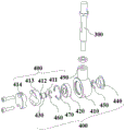
FIG. 4: an exploded view of a second rotary joint;
FIG. 5: a cross-sectional view of the second rotary joint;
FIG. 6: an exploded view of a third revolute joint;
FIG. 7: a cross-sectional view of the third rotary joint;
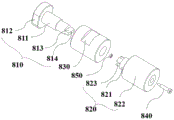
FIG. 8: an exploded view of the angle adjuster;
FIG. 9: angle regulator use state reference diagram (one);
FIG. 10: the angle regulator using state reference diagram (II);
FIG. 11: the angle regulator use state refers to the drawing (three).
In the figure, 100, mounting rod;
200. a first rotary joint; 210. a first shaft seat; 213. a first mounting hole; 220. a first bearing; 230. a first rotating shaft; 240. a first end cap; 250. a clamp spring is arranged on the first inner ring; 260. a first inner ring lower clamp spring; 270. a first outer ring clamp spring; 280. a first limit step; 290. a first threaded hole; 211. a first upper limiting groove; 212. a first lower limiting groove;
300. a first link;
400. a second rotary joint; 410. a second shaft base; 420. a second bearing; 430. a second rotating shaft; 440. a second end cap; 450. a second inner ring right clamp spring; 460. a second inner ring left clamp spring; 470. a second outer ring snap spring; 480. a second limit step; 490. a second threaded hole; 411. a second right limiting groove; 412. a second left limiting groove; 413. a first buckle; 414. a second buckle;
500. a second link;
600. a third rotary joint; 610. a third shaft seat; 611. a third rear limiting groove; 612. a third front limiting groove; 620. a third bearing; 630. a third rotating shaft; 640. a third end cap; 650. a third inner ring back clamp spring; 660. a third inner ring front clamp spring; 670. a third outer ring clamp spring; 680. a third limiting step; 690. a third threaded hole;
700. a fixed mount; 710. a connecting arm; 720. a first fixed arm; 730. a second fixed arm; 740. fastening screws;
800. an angle adjuster; 810. a first connection portion; 811. a first threaded connection; 812. a first blocking portion; 813. a character key; 814. a threaded hole; 820. a second connecting portion; 821. a second threaded connection; 822. a second blocking portion; 823. a cross keyway; 824. a through hole; 825. a retainer ring; 830. a sleeve; 840. a bolt; 850. and locking the nut.
Detailed Description
For a further understanding of the present invention, reference will be made to the following detailed description taken in conjunction with the accompanying drawings and examples.
The structure, ratio, size and the like shown in the drawings of the present specification are only used for matching with the content disclosed in the specification, so as to be known and read by people familiar with the technology, and are not used for limiting the limit conditions which can be implemented by the present invention, so that the present invention does not have the substantial significance in the technology, and any structure modification, ratio relationship change or size adjustment should still fall within the scope which can be covered by the technical content disclosed by the present invention without affecting the efficacy which can be produced by the present invention and the achievable purpose. Meanwhile, the terms such as "upper", "lower", "left", "right", "middle", and the like, referred to in the present specification, are used for clarity of description only, and are not used to limit the implementable scope, and changes or adjustments of the relative relationship thereof are also regarded as the implementable scope of the present invention without substantial changes in the technical content; in addition, the embodiments of the present invention are not independent of each other, but can be combined.
The tool support for the mechanical arm comprises a mounting rod 100 for mounting on the mechanical arm, the mounting rod 100 can also be mounted on other instruments including but not limited to mechanical arms for similar assistance, and in addition, the mounting rod 100 is detachably mounted on the mechanical arms.
The tool holder for a robot arm of the present embodiment is disposed at the free end of the robot arm, that is, is mounted at the free end of the robot arm through the mounting rod 100, so that the tool holder for a robot arm is disposed on the robot arm, and the robot arm capable of holding a tool is formed. The free end of the mechanical arm is the end of the mechanical arm used for installing a tool for operation in the using process.
As shown in fig. 1, the tool holder for a robot arm includes a mounting bar 100, a link, a rotary joint, and a fixing frame 700, the link includes a first link 300 and a second link 500, each of the first link 300 and the second link 500 includes a horizontal portion, a vertical portion, and a bent portion, and the horizontal portion is connected to the vertical portion by the bent portion, thereby forming an "L-shaped" structure. The rotary joint includes a first rotary joint 200, a second rotary joint 400, and a third rotary joint 600. Installation pole 100 is connected with first connecting rod 300 through first rotary joint 200 including I section of installation pole and II sections of installation pole, the one end that II sections of installation pole were kept away from to I section of installation pole is connected with arm detachably. It should be noted that the first rotating shaft 230 of the first rotating joint 200 is perpendicular to the mounting rod 100, the lower end of the first rotating shaft 230 is connected to the horizontal portion of the first link 300, the lower end of the vertical portion of the first link 300 is connected to the second rotating joint 400, and the second rotating shaft 430 of the second rotating joint 400 is perpendicular to the vertical portion of the first link 300. The second rotating shaft 430 of the second rotary joint 400 is connected to a second connecting rod 500, the other end of the second connecting rod 500 is connected to a third rotary joint 600, and a third rotating shaft 630 of the third rotary joint 600 is connected to the fixing frame 700. Furthermore, the rotation axis of the first rotary joint 200 and the rotation axis of the second rotary joint 400 are perpendicular to each other, and the rotation axis of the first rotary joint 200 and the rotation axis of the third rotary joint 600 are perpendicular to each other; the rotation axis of the second rotary joint 400 and the rotation axis of the third rotary joint 600 are perpendicular to each other.
Further describing the fixing frame 700, as shown in fig. 1, the fixing frame 700 includes a connecting arm 710, a first fixing arm 720 and a second fixing arm 730, fixing holes are formed in the connecting arm 710, the first fixing arm 720 and the second fixing arm 730, fastening screws 740 are arranged in the fixing holes of the first fixing arm 720 and the second fixing arm 730 in a matching manner, and the connecting arm 710 is connected with the third rotary joint 600 through the fixing holes. The fastening screw 740 includes a rotation arm and a screw body, and the rotation arm is disposed at one end of the screw body and forms a structure similar to an "L" shape with the screw body.
As shown in fig. 2, the first rotary joint 200 includes a first shaft seat 210, a first bearing 220, a first rotary shaft 230, a first end cover 240, a first inner ring upper snap spring 250, a first inner ring lower snap spring 260, and a first outer ring snap spring 270. As shown in fig. 3, the outer ring of the first bearing 220 is matched with the first shaft holder 210, a first limit step 280 and a first clamping groove are arranged in the first shaft holder 210, the upper end of the outer ring of the first bearing 220 abuts against the first limit step 280, and the first outer ring snap spring 270 is installed in the first clamping groove and abuts against the lower end of the outer ring of the first bearing 220. The inner ring of the first bearing 220 is matched with the first rotating shaft 230, a first upper limiting groove 211 and a first lower limiting groove 212 are arranged on the first rotating shaft 230, the first rotating shaft 230 is inserted into the first bearing 220, the first inner ring upper clamp spring 250 is installed in the first upper limiting groove 211, the first inner ring lower clamp spring 260 is installed in the first lower limiting groove 212, the first inner ring upper clamp spring 250 abuts against the upper end of the inner ring of the first bearing 220, and the first inner ring lower clamp spring 260 abuts against the lower end of the inner ring of the first bearing 220. The first shaft holder 210 is provided with a first threaded hole 290 perpendicular to the first rotating shaft 230, and the first threaded hole 290 is threadedly coupled to the mounting rod 100 and fastened thereto by a nut. The first rotating shaft 230 has a first mounting hole 213 formed at a lower end thereof, and the horizontal portion of the first link 300 passes through the first mounting hole 213 and is fixed by nuts at both ends thereof.
As shown in fig. 4, the second rotary joint 400 includes a second shaft seat 410, a second bearing 420, a second rotating shaft 430, a second end cover 440, a second inner ring right snap spring 450, a second inner ring left snap spring 460, and a second outer ring snap spring 470. As shown in fig. 5, the outer ring of the second bearing 420 is matched with the second shaft seat 410, a second limiting step 480 and a second clamping groove are arranged in the second shaft seat 410, the right end of the outer ring of the second bearing 420 abuts against the second limiting step 480, and the second outer ring clamping spring 470 is arranged in the second clamping groove and abuts against the left end of the outer ring of the second bearing 420. The inner ring of the second bearing 420 is matched with the second rotating shaft 430, a second right limiting groove 411 and a second left limiting groove 412 are arranged on the second rotating shaft 430, the second rotating shaft 430 is inserted into the second bearing 420, the second inner ring right clamp spring 450 is installed in the second right limiting groove 411, the second inner ring left clamp spring 460 is installed in the second left limiting groove 412, the second inner ring right clamp spring 450 abuts against the right end of the inner ring of the second bearing 420, and the second inner ring left clamp spring 460 abuts against the left end of the inner ring of the second bearing 420. The second shaft holder 410 is provided with a second screw hole 490 perpendicular to the second shaft 430, and the second screw hole 490 is screw-coupled to the lower end of the first link 300 and is locked by a nut. The left end of second pivot 430 is provided with first buckle 413, is provided with the arc wall on the first buckle 413, is provided with second buckle 414 with first buckle 413 correspondence, also is provided with the arc wall on the second buckle 414. The first buckle 413 and the second buckle 414 are buckled oppositely, so that the arc-shaped grooves on the first buckle 413 and the second buckle 414 form a locking groove, and one end of the second connecting rod 500 is inserted into the locking groove and locked by a screw connecting the first buckle 413 and the second buckle 414.
As shown in fig. 6, the third rotary joint 600 includes a third shaft seat 610, a third bearing 620, a third rotary shaft 630, a third end cover 640, a third inner-ring rear snap spring 650, a third inner-ring front snap spring 660, and a third outer-ring snap spring 670. As shown in fig. 7, the outer ring of the third bearing 620 is matched with the third shaft seat 610, a third limiting step 680 and a third clamping groove are arranged in the third shaft seat 610, the rear end of the outer ring of the third bearing 620 abuts against the third limiting step 680, and the third outer ring snap spring 670 is installed in the third clamping groove and abuts against the front end of the outer ring of the third bearing 620. The inner ring of the third bearing 620 is matched with the third rotating shaft 630, a third rear limiting groove 611 and a third front limiting groove 612 are arranged on the third rotating shaft 630, the third rotating shaft 630 is inserted into the third bearing 620, the third inner ring rear clamp spring 650 is installed in the third rear limiting groove 611, the third inner ring front clamp spring 660 is installed in the third front limiting groove 612, the third inner ring rear clamp spring 650 abuts against the rear end of the inner ring of the third bearing 620, and the third inner ring front clamp spring 660 abuts against the front end of the inner ring of the third bearing 620. The third shaft holder 610 is provided with a third threaded hole 690 perpendicular to the third shaft 630, and the third threaded hole 690 is in threaded connection with one end of the second link 500 and is locked by a nut. The third rotating shaft 630 is coupled to the fixing frame 700 and is locked by a nut.
As shown in fig. 8, the present invention provides an angle adjuster 800, which includes a first connecting portion 810, a second connecting portion 820, a sleeve 830, a bolt 840, and a lock nut 850. Wherein the first coupling part 810 includes a first threaded coupling part 811 and a first blocking part 812, and a diameter of the first blocking part 812 is larger than a diameter of the first threaded coupling part 811. The first threaded connection portion 811 is provided with an external thread, the end portion of the first threaded connection portion 811 is provided with a first key 813, and the end surface of the first key 813 is provided with a threaded hole 814. The second coupling part 820 includes a second threaded coupling part 821 and a second blocking part 822, and the diameter of the second blocking part 822 is larger than that of the second threaded coupling part 821. The second threaded portion 821 is provided with an external thread, and the end portion of the second threaded portion 821 is provided with a cross key groove 823.
As shown in fig. 8, an axially extending through hole 824 is provided in the second connecting portion 820, and a retaining ring 825 is provided in the through hole 824 at the second threaded portion 821. The bolt 840 is inserted into the through hole 824, the bolt head of the bolt 840 cooperates with the retainer ring 825 to limit the limit range of the reverse movement of the first connecting portion 810 and the second connecting portion 820, when the bolt head of the bolt 840 abuts against the retainer ring 825, the first connecting portion 810 and the second connecting portion 820 move in opposite directions to the farthest position, the retainer ring 825 limits the reverse movement stroke of the first connecting portion 810 relative to the second connecting portion 820, and meanwhile, the retainer ring also prevents the first connecting portion and the second connecting portion from being completely separated due to the fact that the bolt falls off from the second connecting portion when the sleeve is completely located on the first connecting portion. The end of the shank of the bolt 840 is coupled with the threaded hole 814, thereby accomplishing the coupling of the first coupling portion 810 and the second coupling portion 820. And the bolt 840 is locked with the threaded hole 814 by the locking nut 850, so that the bolt 840 is prevented from being gradually separated from the first coupling portion 810 when the first coupling portion 810 is rotated, i.e., the bolt is prevented from falling off from the threaded hole of the first coupling portion. The locking nut 850 abuts against a limit step on the bolt 840. The key 813 may also be provided on the second connection part 820 and the cross key slot 823 on the first connection part 810, and accordingly, the through hole 824 is provided on the first connection part 810. It should be noted that the through hole 824 may be provided in the first connecting portion 810, and an end opening through which the through hole passes is located on an end surface of the key 813, and accordingly, the screw hole 814 is provided in the second connecting portion 820.
The sleeve 830 is internally threaded and is threadably coupled to the first threaded portion 811 and the second threaded portion 821. The first connecting portion 810 and the second connecting portion 820 are movable in the axial direction of the bolt 840, and the key 813 may be inserted into or pulled out of the cross key groove 823. When the I-key 813 is pulled out from the cross-shaped key slot 823, the first connecting part 810 and the second connecting part 820 can rotate relatively, so as to adjust the angle as required. The key at the end of the first threaded portion 811 and the key slot at the end of the second threaded portion 821 may be provided as internal and external splines, or may be provided in various forms such as an annular column and an annular hole, according to the requirement of angle adjustment. The sleeve 830 is provided with an anti-slip groove, and the sleeve 830 is rotated by pinching the anti-slip groove.
The operation of angle adjuster 800 will now be described in detail with reference to fig. 9, 10 and 11. As shown in fig. 9, fig. 9A shows a cross-sectional view in the use state, and fig. 9B shows a front view in the use state. When the first connecting portion 810 and the second connecting portion 820 need to be adjusted in angle, the sleeve 830 is rotated leftwards to abut against the first blocking portion 812, at this time, the internal thread at the right end of the sleeve 830 is separated from the second threaded connecting portion 821, and the linear key 813 can be pulled out from the cross-shaped key groove 823. When the head of the bolt 840 abuts against the retainer ring 825, the first connecting portion 810 and the second connecting portion 820 move in opposite directions to the farthest position, the first connecting portion 810 can rotate relative to the second connecting portion 820, and the I-shaped key 813 is aligned with the cross-shaped key slot 823 every 90 degrees of rotation. The key 813 and the cross key slot 823 limit the angle of rotation of the first connecting part 810 and the second connecting part 820, for example, if the key 813 cannot be inserted into the cross key slot 823 every time the key is rotated by 100 °. As shown in fig. 10, fig. 10A is a cross-sectional view in the use state, and fig. 10B is a front view in the use state. When the first connecting part 810 and the second connecting part 820 are rotated by multiples of 90 degrees, the I-shaped key 813 is inserted into the cross-shaped key slot 823 again. As shown in fig. 11, fig. 11A is a cross-sectional view in the use state, and fig. 11B is a front view in the use state. The sleeve 830 is rotated rightward until the internal thread at the right end of the sleeve 830 is connected with the external thread of the second threaded connection portion 821, the first connection portion 810 and the second connection portion 820 are connected and fixed through the sleeve 830, the first connection portion 810 and the second connection portion 820 are locked, and the angle adjustment of the first connection portion 810 and the second connection portion 820 is completed. As shown in fig. 1, the angle adjuster 800 is installed on the vertical portion of the mounting rod 100 and the first link 300, and the axis of the angle adjuster 800 on the mounting rod 100 and the axis of the angle adjuster 800 on the first link 300 are perpendicular to each other. Installation pole 100 includes I section of installation pole and II sections of installation pole, and angle adjuster 800 sets up between I section of installation pole and II sections of installation pole. The bent portion of the first link 300 is provided with a bent vertical section, and the angle adjuster 800 is disposed between the bent vertical section and the vertical portion of the first link 300.
The invention has been described above in detail with reference to specific exemplary embodiments. It will, however, be understood that various modifications and changes may be made without departing from the scope of the invention as defined by the appended claims. The detailed description and drawings are to be regarded as illustrative rather than restrictive, and any such modifications and variations are intended to be included within the scope of the present invention as described herein. Furthermore, the background is intended to illustrate the present state of the art and the meaning of the present development and is not intended to limit the present invention or the present application and the field of application of the present invention.
More specifically, although exemplary embodiments of the invention have been described herein, the invention is not limited to these embodiments, but includes any and all embodiments modified, omitted, such as combinations between various embodiments, adapted changes and/or substitutions as would be recognized by those skilled in the art from the foregoing detailed description. The limitations in the claims are to be interpreted broadly based the language employed in the claims and not limited to examples described in the foregoing detailed description or during the prosecution of the application, which examples are to be construed as non-exclusive. Any steps recited in any method or process claims may be executed in any order and are not limited to the order presented in the claims. The scope of the invention should, therefore, be determined only by the appended claims and their legal equivalents, rather than by the descriptions and examples given above.
Claims (10)
1. The utility model provides a instrument support for arm which characterized in that: the connecting rod comprises a mounting rod (100), a connecting rod, a rotary joint and a fixing frame (700), wherein the connecting rod comprises a first connecting rod (300) and a second connecting rod (500), and the rotary joint comprises a first rotary joint (200), a second rotary joint (400) and a third rotary joint (600); the mounting rod (100) is rotatably connected with one end of the first connecting rod (300) through the first rotary joint (200), the other end of the first connecting rod (300) is rotatably connected with one end of the second connecting rod (500) through the second rotary joint (400), and the other end of the second connecting rod (500) is rotatably connected with the fixed frame (700) through the third rotary joint (600).
2. The tool support for a robot arm according to claim 1, wherein: the connecting rod is an L-shaped connecting rod.
3. The tool support for a robot arm according to claim 1, wherein: the fixing frame (700) comprises a connecting arm (710), a first fixing arm (720) and a second fixing arm (730) which are connected with two ends of the connecting arm (710), fixing holes are formed in the connecting arm (710), the first fixing arm (720) and the second fixing arm (730), fastening screws (740) are arranged in the fixing holes of the first fixing arm (720) and the second fixing arm (730) in a matched mode, a third rotating shaft is arranged on the third rotating joint (600), and the third rotating shaft is installed in the fixing holes of the connecting arm (710).
4. The tool support for a robot arm according to claim 1, wherein: the rotational axis of the first rotary joint (200) and the rotational axis of the second rotary joint (400) are perpendicular to each other, and/or
The rotation axis of the first rotary joint (200) and the rotation axis of the third rotary joint (600) are perpendicular to each other; and/or
The rotation axis of the second rotary joint (400) and the rotation axis of the third rotary joint (600) are perpendicular to each other.
5. The tool support for a robot arm according to claim 1, wherein: the angle adjuster (800) is arranged on the mounting rod (100) and the first connecting rod (300), and the axes of the angle adjuster (800) on the mounting rod (100) and the first connecting rod (300) are perpendicular to each other.
6. The tool support for a robot arm according to claim 5, wherein: the angle adjuster (800) comprises a first connecting part (810), a second connecting part (820) and a sleeve (830), wherein the sleeve (830) is sleeved on the outer surfaces of the first connecting part (810) and the second connecting part in a threaded manner; a key is arranged at the end part of the first connecting part (810), and a matched key slot is arranged at the end part of the second connecting part (820); when the internal thread of the sleeve (830) is separated from the external thread on the first connecting part (810) or the second connecting part (820), the first connecting part and the second connecting part can move in the opposite direction or the opposite direction to realize the insertion connection or the separation of the key and the key slot, after the key is separated from the key slot, the first connecting part (810) and the second connecting part (820) can rotate relatively, and the key slot limit the relative rotation angle of the first connecting part (810) and the second connecting part (820).
7. The tool support for a robot arm according to claim 6, wherein: the first connection part (810) includes a first screw-threaded part (811) and a first blocking part (812), the first blocking part (812) having a diameter greater than that of the first screw-threaded part (811), and the key is provided at an end of the first screw-threaded part (811); when the sleeve (830) is rotated to abut against the first stopper (812), the internal thread of the sleeve (830) is separated from the external thread of the second connecting part (820).
8. The tool support for a robot arm according to claim 6, wherein: the second connecting part (820) comprises a second threaded connecting part (821) and a second blocking part (822), the diameter of the second blocking part (822) is larger than that of the second threaded connecting part (821), an external thread is arranged on the second threaded connecting part (821), and the key groove is arranged at the end part of the second threaded connecting part (821).
9. The tool support for a robot arm according to claim 6, wherein: a threaded hole (814) is formed in the end portion of the first connecting portion (810)/the end portion of the second connecting portion (820), a through hole (824) is formed in the axis of the second connecting portion (820)/the first connecting portion (810), a bolt (840) is arranged in the through hole, and the bolt (840) penetrates through the through hole (824) and then is connected with the threaded hole (814); a retainer ring (825) is arranged in the through hole (824), and the head of the bolt (840) is matched with the retainer ring (825) to limit the stroke of the reverse movement of the first connecting part (810) and the second connecting part (820).
10. The utility model provides a take arm of tool support which characterized in that: a tool holder for a robot arm according to any one of claims 1 to 9 is provided at a free end of the robot arm, and a mounting rod (100) of the tool holder for a robot arm is attached to the free end of the robot arm.
Priority Applications (1)
| Application Number | Priority Date | Filing Date | Title |
|---|---|---|---|
| CN201921497332.XU CN210791023U (en) | 2019-09-06 | 2019-09-06 | Tool support and mechanical arm using same |
Applications Claiming Priority (1)
| Application Number | Priority Date | Filing Date | Title |
|---|---|---|---|
| CN201921497332.XU CN210791023U (en) | 2019-09-06 | 2019-09-06 | Tool support and mechanical arm using same |
Publications (1)
| Publication Number | Publication Date |
|---|---|
| CN210791023U true CN210791023U (en) | 2020-06-19 |
Family
ID=71238062
Family Applications (1)
| Application Number | Title | Priority Date | Filing Date |
|---|---|---|---|
| CN201921497332.XU Active CN210791023U (en) | 2019-09-06 | 2019-09-06 | Tool support and mechanical arm using same |
Country Status (1)
| Country | Link |
|---|---|
| CN (1) | CN210791023U (en) |
Cited By (2)
| Publication number | Priority date | Publication date | Assignee | Title |
|---|---|---|---|---|
| CN112114470A (en) * | 2020-09-24 | 2020-12-22 | 深圳市唯迹科技有限公司 | Light filling equipment and mounting base thereof |
| CN115137484A (en) * | 2022-05-23 | 2022-10-04 | 上海奥朋医疗科技有限公司 | Trailing arm of surgical robot and assembling method thereof |
-
2019
- 2019-09-06 CN CN201921497332.XU patent/CN210791023U/en active Active
Cited By (3)
| Publication number | Priority date | Publication date | Assignee | Title |
|---|---|---|---|---|
| CN112114470A (en) * | 2020-09-24 | 2020-12-22 | 深圳市唯迹科技有限公司 | Light filling equipment and mounting base thereof |
| CN112114470B (en) * | 2020-09-24 | 2022-04-15 | 深圳市唯迹科技有限公司 | Light filling equipment and mounting base thereof |
| CN115137484A (en) * | 2022-05-23 | 2022-10-04 | 上海奥朋医疗科技有限公司 | Trailing arm of surgical robot and assembling method thereof |
Similar Documents
| Publication | Publication Date | Title |
|---|---|---|
| US7191494B2 (en) | Stabilizer for rotary tools | |
| US20030143041A1 (en) | Portable drill press | |
| US5642969A (en) | Portable machine tool | |
| CN111113007B (en) | Single-shaft tightening machine | |
| WO1990011147A1 (en) | Rotatable coupling for fastener installation tool | |
| JP7430773B2 (en) | Strut assembly and external fixation system | |
| CN210791022U (en) | Clamping device and mechanical arm using same | |
| DE102010035551B4 (en) | Tool for a robot and method for producing a screw connection | |
| EP2490569B1 (en) | Telescopic arm for a pc table | |
| CN207228432U (en) | Glass plate fixing device for installing | |
| CN216044847U (en) | Positioning adjusting device | |
| CN107605913B (en) | Adjustable anti-drop bolt | |
| CN220699382U (en) | Adjusting device and clamp | |
| WO2005095033A1 (en) | Material guide device and automatic lathe | |
| US20190140528A1 (en) | Adapter for motor replacement and motor replacement method | |
| CN2471484Y (en) | Adjustable angle hand tools | |
| CN110905175B (en) | Tool for plastering internal and external corners | |
| JP2781068B2 (en) | Roller upsetting tool | |
| CN118696179A (en) | Swivel bearings for ceiling mounts | |
| CN219054061U (en) | Universal sand blasting gun | |
| CN112388565B (en) | Screw tightening mechanism with controllable inclination angle alignment and operation method | |
| CN224222755U (en) | Positioning device for lathe machining | |
| CN220145770U (en) | Shaft part positioning device | |
| CN208427893U (en) | A kind of pipe fitting flange positioning fixture | |
| CN107520804B (en) | An adjustable and removable connecting plate and its application |
Legal Events
| Date | Code | Title | Description |
|---|---|---|---|
| GR01 | Patent grant | ||
| GR01 | Patent grant | ||
| EE01 | Entry into force of recordation of patent licensing contract |
Assignee: NINGBO SUNRISE INDUSTRIAL AUTOMATION Co.,Ltd. Assignor: SHENYANG RUISHENG INTELLIGENT EQUIPMENT Co.,Ltd. Contract record no.: X2023980053848 Denomination of utility model: A tool holder and a robotic arm using the tool holder Granted publication date: 20200619 License type: Common License Record date: 20231225 |
|
| EE01 | Entry into force of recordation of patent licensing contract |