CN210790763U - A horizontal cabinet assembly jig - Google Patents
A horizontal cabinet assembly jig Download PDFInfo
- Publication number
- CN210790763U CN210790763U CN201920888918.2U CN201920888918U CN210790763U CN 210790763 U CN210790763 U CN 210790763U CN 201920888918 U CN201920888918 U CN 201920888918U CN 210790763 U CN210790763 U CN 210790763U
- Authority
- CN
- China
- Prior art keywords
- bracket
- support rod
- rod group
- frame
- elastic member
- Prior art date
- Legal status (The legal status is an assumption and is not a legal conclusion. Google has not performed a legal analysis and makes no representation as to the accuracy of the status listed.)
- Active
Links
Images
Landscapes
- Assembled Shelves (AREA)
Abstract
本实用新型公开了一种卧式机柜组装治具,属于机柜技术领域;一种卧式机柜组装治具,包括机架、第一弹力件、第二弹力件,机架上依次连接有第一支架、第二支架、第三支架,机架上连接有转轴,转轴上转动连接有第一支撑杆组,第一支撑杆组远离转轴的一端连接有第二支撑杆组,第一弹力件的一端与机架转动相连,第一弹力件的另一端与第一支撑杆组转动相连,第二弹力件的一端与第一支撑杆组转动相连,第二弹力件远离第一支撑杆组的一端与第二支撑杆组转动相连;本实用新型在对组合型机柜进行安装时,提高了安装效率,减轻人工劳动,可连续性快速进行组装。

The utility model discloses a horizontal cabinet assembling jig, belonging to the technical field of cabinets; a horizontal cabinet assembling jig, comprising a frame, a first elastic piece and a second elastic piece, and a first elastic piece is connected to the frame in sequence. The bracket, the second bracket and the third bracket, the frame is connected with a rotating shaft, the rotating shaft is rotatably connected with a first support rod group, the end of the first support rod group away from the rotating shaft is connected with a second support rod group, and the first elastic member is connected to the second support rod group. One end is rotatably connected with the frame, the other end of the first elastic piece is rotatably connected with the first support rod group, one end of the second elastic piece is rotatably connected with the first support rod group, and the second elastic piece is away from the end of the first support rod group The utility model is rotatably connected with the second support rod group; when the combined cabinet is installed, the utility model improves the installation efficiency, reduces the manual labor, and can be assembled continuously and rapidly.
Description
技术领域technical field
本实用新型涉及机柜技术领域,尤其涉及一种卧式机柜组装治具。The utility model relates to the technical field of cabinets, in particular to a horizontal cabinet assembly fixture.
背景技术Background technique
机柜一般是冷轧钢板或合金制作的用来存放计算机和相关控制设备的物件,可以提供对存放设备的保护,屏蔽电磁干扰,有序、整齐地排列设备,方便以后维护设备,机柜一般用在网络布线间、楼层配线间、中心机房、数据机房、控制中心等,机柜一般分为服务器机柜、网络机柜、控制台机柜等,当前组装式机柜广泛用于市场,其便于拆卸、维修、携带;Cabinets are generally objects made of cold-rolled steel plates or alloys to store computers and related control equipment. They can provide protection for storage equipment, shield electromagnetic interference, and arrange equipment in an orderly and neat manner to facilitate future maintenance of equipment. Cabinets are generally used in Network wiring room, floor wiring room, central computer room, data computer room, control center, etc. Cabinets are generally divided into server cabinets, network cabinets, console cabinets, etc. At present, assembled cabinets are widely used in the market, which are easy to disassemble, maintain, and carry. ;
经检索如专利号为:CN200710075956.8,公告日为:2010-01-20公开了一种机柜的结构,特别涉及一种组装式网络机柜,所述组装式机柜由二块盖板和连接在二块盖板之间的二条或四条设备安装条组成,所述设备安装条用螺钉与盖板直接固接;设备安装条同时起到机柜立柱功能;所述设备安装条可以根据需要安装在盖板设备安装条安装面不同安装孔的位置。这种组装式网络机柜具有结构简单、安装使用方便、包装体积小的优点。After searching, the patent number is: CN200710075956.8, and the announcement date is: 2010-01-20. The structure of a cabinet is disclosed, especially an assembled network cabinet. Two or four equipment installation strips are formed between the two cover plates. The equipment installation strips are directly fixed to the cover plate with screws; the equipment installation strips also function as cabinet columns; the equipment installation strips can be installed on the cover plate as required. The positions of the different mounting holes on the mounting surface of the board equipment mounting strip. The assembled network cabinet has the advantages of simple structure, convenient installation and use, and small packaging volume.
在如专利号为:CN201310378714.1,公告日为:2017-12-22公开了一种机柜,包括第一横梁、第二横梁、盖板、底板、围框及门框。第一横梁设有第一凹槽和第二凹槽,第二横梁设有第一卡槽和第二卡槽,门框设有第一固定槽。盖板插入第一凹槽,底板插入第一卡槽,围框的一个端部收容于第二凹槽,围框的另一个端部收容于第二卡槽,盖板的前端、底板的前端和围框的前端均插入第一固定槽中,以将第一横梁、第二横梁、盖板、底板、围框及门框组装为机柜。本实用新型提供的机柜,利用第一横梁的第一凹槽和第二凹槽、第二横梁的第一卡槽和第二卡槽及门框的第一固定槽就可以将第一横梁、第二横梁、盖板、底板、门框及围框组装为机柜,解决了现有技术因机柜整体焊接而导致的工作量大的问题。For example, the patent number is: CN201310378714.1, and the announcement date is: 2017-12-22. A cabinet is disclosed, which includes a first beam, a second beam, a cover plate, a bottom plate, an enclosure frame and a door frame. The first beam is provided with a first groove and a second groove, the second beam is provided with a first clamping groove and a second clamping groove, and the door frame is provided with a first fixing groove. The cover plate is inserted into the first groove, the bottom plate is inserted into the first card groove, one end of the surrounding frame is received in the second groove, the other end of the surrounding frame is received in the second card groove, the front end of the cover plate and the front end of the bottom plate are received in the second groove. The front end of the enclosure frame and the enclosure frame are inserted into the first fixing groove to assemble the first beam, the second beam, the cover plate, the bottom plate, the enclosure frame and the door frame into a cabinet. In the cabinet provided by the utility model, the first cross beam and the second Two beams, a cover plate, a bottom plate, a door frame and a surrounding frame are assembled into a cabinet, which solves the problem of heavy workload caused by the overall welding of the cabinet in the prior art.
以上两篇对比文件均达到便于拆卸和维修,但是当前在对机柜进行组装时,多为人工将各个板件搬起对孔安装螺丝,由于机柜的重量较重,随着安装部件的增加则安装越费力,而目前市场上没有对组合式机柜进行组装的设备,为此我们提出一种卧式机柜组装治具来解决以上问题。The above two comparison documents are both easy to disassemble and maintain. However, when assembling the cabinet, most of the panels are manually moved to the holes to install the screws. Due to the heavy weight of the cabinet, as the number of installation parts increases, it is installed. The more laborious it is, and there is currently no equipment for assembling combined cabinets on the market, we propose a horizontal cabinet assembly fixture to solve the above problems.
实用新型内容Utility model content
本实用新型的目的是为了解决现有技术中的不足,而提出的一种卧式机柜组装治具。The purpose of the utility model is to propose a horizontal cabinet assembling fixture in order to solve the deficiencies in the prior art.
为了实现上述目的,本实用新型采用了如下技术方案:In order to achieve the above-mentioned purpose, the utility model adopts the following technical solutions:
一种卧式机柜组装治具,包括机架、第一弹力件、第二弹力件,所述机架上依次连接有第一支架、第二支架、第三支架,所述机架上连接有转轴,所述转轴上转动连接有第一支撑杆组,所述第一支撑杆组远离转轴的一端连接有第二支撑杆组,所述第一弹力件的一端与机架转动相连,所述第一弹力件的另一端与第一支撑杆组转动相连,所述第二弹力件的一端与第一支撑杆组转动相连,所述第二弹力件远离第一支撑杆组的一端与第二支撑杆组转动相连。A horizontal cabinet assembly jig comprises a frame, a first elastic piece and a second elastic piece, wherein a first bracket, a second bracket and a third bracket are sequentially connected to the frame, and the frame is connected with a first bracket, a second bracket and a third bracket. A rotating shaft, on which a first support rod group is rotatably connected, an end of the first support rod group away from the rotating shaft is connected with a second support rod group, and one end of the first elastic member is rotatably connected with the frame, the The other end of the first elastic member is rotatably connected with the first support rod group, one end of the second elastic member is rotatably connected with the first support rod group, and the end of the second elastic member away from the first support rod group is connected with the second support rod group. The support rod group is connected in rotation.
优选的,所述机架上位于第一支架、第二支架、第三支架处均连接有磁铁。Preferably, magnets are connected to the frame at the first bracket, the second bracket and the third bracket.
优选的,所述第一支架、第二支架、第三支架上均连接有大头针。Preferably, pins are connected to the first bracket, the second bracket and the third bracket.
优选的,所述机架上连接有多组肘节夹,所述机架上转动连接有多组滚轮。Preferably, multiple sets of toggle clamps are connected to the frame, and multiple sets of rollers are rotatably connected to the frame.
优选的,所述第一支架、第二支架、第三支架上均连接有卡板,所述第一支架、第二支架、第三支架与机架之间连接有支撑架。Preferably, the first bracket, the second bracket, and the third bracket are all connected with a card board, and a support frame is connected between the first bracket, the second bracket, the third bracket and the frame.
与现有技术相比,本实用新型提供了一种卧式机柜组装治具,具备以下有益效果:Compared with the prior art, the utility model provides a horizontal cabinet assembly fixture, which has the following beneficial effects:
1、该卧式机柜组装治具,通过将底座、托盘、顶基组件分别放在第三支架、第二支架、第一支架上,并通过磁铁和大头针将其固定,然后在将左右门框与底座、托盘、顶基组件进行安装,并通过肘节夹进行固定,然后通过两个人同时用螺丝将左右门框锁紧,组装完成后,松开肘节夹并推动机柜,通过第一支撑杆组和第二支撑杆组在第一弹力件和第二弹力件的作用下对机柜进行支撑,使其平稳落地,本实用新型,在对组合型机柜进行安装时,提高了安装效率,减轻人工劳动,可连续性快速进行组装。1. The horizontal cabinet assembly fixture is to place the base, tray and top base components on the third bracket, the second bracket and the first bracket respectively, and fix them with magnets and pins, and then connect the left and right door frames to the first bracket. The base, tray, and top base components are installed and fixed by toggle clamps, and then the left and right door frames are locked with screws at the same time by two people. and the second support rod group support the cabinet under the action of the first elastic piece and the second elastic piece to make it land smoothly. The utility model improves the installation efficiency and reduces the manual labor when the combined cabinet is installed. , which can be assembled quickly and continuously.
附图说明Description of drawings
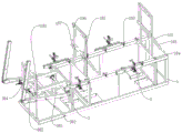
图1为本实用新型提出的一种卧式机柜组装治具的结构示意图一;Fig. 1 is a structural schematic diagram 1 of a horizontal cabinet assembly fixture proposed by the utility model;
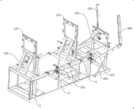
图2为本实用新型提出的一种卧式机柜组装治具的结构示意图二;FIG. 2 is a second structural schematic diagram of a horizontal cabinet assembly jig proposed by the utility model;
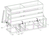
图3为本实用新型提出的一种卧式机柜组装治具的装配图。FIG. 3 is an assembly diagram of a horizontal cabinet assembly jig proposed by the utility model.
图中:1、机架;101、第一支架;102、第二支架;103、第三支架;104、磁铁;105、滚轮;106、大头针;107、卡板;108、支撑架;2、肘节夹;3、转轴;301、第一支撑杆组;302、第一弹力件;303、第二弹力件;304、第二支撑杆组。In the figure: 1, rack; 101, first bracket; 102, second bracket; 103, third bracket; 104, magnet; 105, roller; 106, pin; 107, card board; 108, support frame; 2, Toggle clamp; 3. Rotating shaft; 301, first support rod group; 302, first elastic member; 303, second elastic member; 304, second support rod group.
具体实施方式Detailed ways
下面将结合本实用新型实施例中的附图,对本实用新型实施例中的技术方案进行清楚、完整地描述,显然,所描述的实施例仅仅是本实用新型一部分实施例,而不是全部的实施例。The technical solutions in the embodiments of the present utility model will be clearly and completely described below with reference to the accompanying drawings in the embodiments of the present utility model. Obviously, the described embodiments are only a part of the embodiments of the present utility model, rather than all the implementations. example.
在本实用新型的描述中,需要理解的是,术语“上”、“下”、“前”、“后”、“左”、“右”、“顶”、“底”、“内”、“外”等指示的方位或位置关系为基于附图所示的方位或位置关系,仅是为了便于描述本实用新型和简化描述,而不是指示或暗示所指的装置或元件必须具有特定的方位、以特定的方位构造和操作,因此不能理解为对本实用新型的限制。In the description of the present invention, it should be understood that the terms "upper", "lower", "front", "rear", "left", "right", "top", "bottom", "inside", The orientation or positional relationship indicated by "outside" is based on the orientation or positional relationship shown in the accompanying drawings, which is only for the convenience of describing the present invention and simplifying the description, rather than indicating or implying that the indicated device or element must have a specific orientation , are constructed and operated in a specific orientation, and therefore should not be construed as a limitation of the present invention.
参照图1-3,一种卧式机柜组装治具,包括机架1、第一弹力件302、第二弹力件303,机架1上依次连接有第一支架101、第二支架102、第三支架103,机架1上连接有转轴3,转轴3上转动连接有第一支撑杆组301,第一支撑杆组301远离转轴3的一端连接有第二支撑杆组304,第一弹力件302的一端与机架1转动相连,第一弹力件302的另一端与第一支撑杆组301转动相连,第二弹力件303的一端与第一支撑杆组301转动相连,第二弹力件303远离第一支撑杆组301的一端与第二支撑杆组304转动相连。1-3, a horizontal cabinet assembly jig includes a rack 1, a first
机架1上位于第一支架101、第二支架102、第三支架103处均连接有磁铁104。
第一支架101、第二支架102、第三支架103上均连接有大头针106。The
机架1上连接有多组肘节夹2,机架1上转动连接有多组滚轮105。A plurality of sets of toggle clamps 2 are connected to the frame 1 , and a plurality of sets of
第一支架101、第二支架102、第三支架103上均连接有卡板107,第一支架101、第二支架102、第三支架103与机架1之间连接有支撑架108。The
其操作方法如下:Its operation method is as follows:
S1:将机柜的底座放置在第三支架103上,并进行固定;S1: Place the base of the cabinet on the
S2:将机柜内托盘放置到第二支架102上,并进行固定;S2: Place the tray in the cabinet on the
S3:将机柜内的顶基组件放置在第一支架101上,并进行固定;S3: place the top base assembly in the cabinet on the
S4:将左门框放置到机架1的一侧,并与底座、托盘、顶基组件通过定位块和钮子夹定位;S4: Place the left door frame on one side of the rack 1, and position it with the base, tray, and top base components through positioning blocks and button clips;
S5:将右门框放置到机架1的另一侧,并与底座、托盘、顶基组件与右门框进行固定;S5: Place the right door frame on the other side of the rack 1, and fix it with the base, tray, top base assembly and the right door frame;
S6:延续S5两个人同时用螺丝将左右门框锁紧;S6: Continuing from S5, two people lock the left and right door frames with screws at the same time;
S7:设置母线;S7: set the bus;
S8:将组装好的机柜延第三支架103的方向移动大约260毫米;S8: Move the assembled cabinet along the direction of the
S9:垂直移动机柜,通过第一支撑杆组301、第二支撑杆组304、第一弹力件302、第二弹力件303使机柜缓慢移动到地面;S9: Move the cabinet vertically, and slowly move the cabinet to the ground through the first
S10:第一支撑杆组301、第二支撑杆组304自动复位。S10: The first
第一支撑杆组301和第二支撑杆组304均由两根连杆组成。Both the first
S1-S3中采用磁铁104和大头针106进行固定。
S5中通过肘节夹2将右门框进行固定。In S5, the right door frame is fixed by the toggle clamp 2.
S8中通过滚轮105将机柜进行移动。In S8, the cabinet is moved by the
工作原理:使用者使用时,通过将底座、托盘、顶基组件分别放在第三支架103、第二支架102、第一支架101上,并通过磁铁104和大头针106将其固定,然后在将左右门框与底座、托盘、顶基组件进行安装,并通过肘节夹2进行固定,然后通过两个人同时用螺丝将左右门框锁紧,组装完成后,松开肘节夹2并推动机柜,通过第一支撑杆组301和第二支撑杆组304在第一弹力件302和第二弹力件303的作用下对机柜进行支撑,使其平稳落地,本实用新型,在对组合型机柜进行安装时,提高了安装效率,减轻人工劳动,可连续性快速进行组装。Working principle: when the user uses it, the base, the tray, and the top base assembly are placed on the
以上所述,仅为本实用新型较佳的具体实施方式,但本实用新型的保护范围并不局限于此,任何熟悉本技术领域的技术人员在本实用新型揭露的技术范围内,根据本实用新型的技术方案及其实用新型构思加以等同替换或改变,都应涵盖在本实用新型的保护范围之内。The above description is only a preferred embodiment of the present invention, but the protection scope of the present invention is not limited to this. Equivalent replacement or modification of the new technical solution and its utility model concept shall be included within the protection scope of the present utility model.
Claims (5)
Priority Applications (1)
| Application Number | Priority Date | Filing Date | Title |
|---|---|---|---|
| CN201920888918.2U CN210790763U (en) | 2019-06-13 | 2019-06-13 | A horizontal cabinet assembly jig |
Applications Claiming Priority (1)
| Application Number | Priority Date | Filing Date | Title |
|---|---|---|---|
| CN201920888918.2U CN210790763U (en) | 2019-06-13 | 2019-06-13 | A horizontal cabinet assembly jig |
Publications (1)
| Publication Number | Publication Date |
|---|---|
| CN210790763U true CN210790763U (en) | 2020-06-19 |
Family
ID=71237306
Family Applications (1)
| Application Number | Title | Priority Date | Filing Date |
|---|---|---|---|
| CN201920888918.2U Active CN210790763U (en) | 2019-06-13 | 2019-06-13 | A horizontal cabinet assembly jig |
Country Status (1)
| Country | Link |
|---|---|
| CN (1) | CN210790763U (en) |
Cited By (1)
| Publication number | Priority date | Publication date | Assignee | Title |
|---|---|---|---|---|
| CN110315463A (en) * | 2019-06-13 | 2019-10-11 | 和信精密科技(吴江)有限公司 | A kind of horizontal cabinet assembled fixture |
-
2019
- 2019-06-13 CN CN201920888918.2U patent/CN210790763U/en active Active
Cited By (1)
| Publication number | Priority date | Publication date | Assignee | Title |
|---|---|---|---|---|
| CN110315463A (en) * | 2019-06-13 | 2019-10-11 | 和信精密科技(吴江)有限公司 | A kind of horizontal cabinet assembled fixture |
Similar Documents
| Publication | Publication Date | Title |
|---|---|---|
| CN102200803A (en) | Memory fixing device | |
| CN110315463A (en) | A kind of horizontal cabinet assembled fixture | |
| CN210052162U (en) | Cabinet for installing data security terminal | |
| CN210831204U (en) | An economic and trade display stand | |
| CN108378629A (en) | A kind of novel mechanical parts sale displaying frame | |
| CN209073802U (en) | A kind of partition for the free dividing space of drawer size that can be freely disassembled | |
| CN209882363U (en) | Multifunctional computer holds rack | |
| CN208224955U (en) | It is a kind of can flexible expansion rear window construction | |
| CN213522782U (en) | A high-strength PCB motherboard | |
| CN211794963U (en) | Reading rack convenient for looking up book information | |
| CN212377660U (en) | An easy-to-assemble cabinet bracket | |
| CN215298137U (en) | Big data user information digital management server | |
| CN210402995U (en) | Layout demonstration table for exhibition hall | |
| CN216352922U (en) | Business administration is publicity board for teaching | |
| CN220107265U (en) | Outdoor power distribution cabinet | |
| CN221887938U (en) | A storage cabinet | |
| CN221042861U (en) | High-stability mobile phone signal amplifier | |
| CN222760568U (en) | Server Base | |
| CN221126537U (en) | Power distribution cabinet frame | |
| CN215636332U (en) | Network cabinet convenient to hang installation | |
| CN209660839U (en) | A detachable shelf | |
| CN221067591U (en) | Seal storage device convenient to deposit | |
| CN211139924U (en) | Plug-type electric installation mechanism for equipment for packing | |
| CN212626759U (en) | A kind of reinforcement structure for power cabinet | |
| CN223582655U (en) | A human resources recruitment information display device |
Legal Events
| Date | Code | Title | Description |
|---|---|---|---|
| GR01 | Patent grant | ||
| GR01 | Patent grant | ||
| CP03 | Change of name, title or address | ||
| CP03 | Change of name, title or address |
Address after: 215200 No. 789, Shanhu West Road, Wujiang Economic and Technological Development Zone, Suzhou City, Jiangsu Province Patentee after: Suzhou Hexin Precision Technology Co.,Ltd. Address before: 215200 No. 789, Shanhu West Road, Wujiang Economic and Technological Development Zone, Suzhou City, Jiangsu Province Patentee before: WELLTRUST PRECISION TECHNOLOGY (WUJIANG) Co.,Ltd. |
|
| CP03 | Change of name, title or address | ||
| CP03 | Change of name, title or address |
Address after: No. 789 Shanhu West Road, Wujiang Economic and Technological Development Zone, Suzhou City, Jiangsu Province, 215299 Patentee after: Welltrust Precision Technology (Wujiang) Co.,Ltd. Country or region after: China Address before: 215200 No. 789, Shanhu West Road, Wujiang Economic and Technological Development Zone, Suzhou City, Jiangsu Province Patentee before: Suzhou Hexin Precision Technology Co.,Ltd. Country or region before: China |