CN210768088U - Novel inclined top roof tent - Google Patents
Novel inclined top roof tent Download PDFInfo
- Publication number
- CN210768088U CN210768088U CN201920877506.9U CN201920877506U CN210768088U CN 210768088 U CN210768088 U CN 210768088U CN 201920877506 U CN201920877506 U CN 201920877506U CN 210768088 U CN210768088 U CN 210768088U
- Authority
- CN
- China
- Prior art keywords
- base
- tent
- groups
- supporting
- roof tent
- Prior art date
- Legal status (The legal status is an assumption and is not a legal conclusion. Google has not performed a legal analysis and makes no representation as to the accuracy of the status listed.)
- Expired - Fee Related
Links
- 230000000149 penetrating effect Effects 0.000 claims description 2
- 238000010586 diagram Methods 0.000 description 3
- 230000007547 defect Effects 0.000 description 1
Images

Landscapes
- Tents Or Canopies (AREA)
Abstract
A novel pentroof roof tent, comprising: the tent comprises a base, a supporting framework, an air pressure supporting rod, a connecting joint, a stay wire, a U-shaped buckle, a cross rod and a cross rod connecting joint, tarpaulin, a roof tent top cover, a flap, a window, a skylight, a doorway and a base entrance; the tent base is composed of two parts, and one end of the tent base is provided with an entrance; the upper part of the supporting framework is in an A shape, the lower part of the supporting framework is in an H shape, the upper part and the lower part of the supporting framework can be folded, and the two groups of supporting frameworks are respectively fixed at the two ends of the base and can be laid down and erected at ninety degrees under the action of the pull wire and the air pressure rod; the tent is provided with a window, a skylight and a doorway, and the roof tent top cover can be used as a car side awning after being opened.
Description
Technical Field
The utility model belongs to the technical field of the roof tent, refer in particular to a pitched roof tent.
Background
At present, roof tents are many in styles, but each style has more or less defects, for example, some roof tents are like a coffin in appearance, the height inside some roof tents is not high enough, a user can feel oppressive when sitting inside the roof tents, some roof tents do not have a skylight, the back rest is not arranged inside many roof tents, and all roof tents almost have only one entrance and exit at present. The existing car roof tent is almost not provided with a car roof tent which has the advantages of convenience, functionality, practicability and attractive appearance. In view of the above, the present inventors have devised the present invention in view of the above-mentioned shortcomings.
Disclosure of Invention
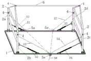
The utility model provides a novel push up roof tent to one side. A novel pentroof roof tent, comprising: the device comprises a base 1, an auxiliary base 1a, two groups of supporting frameworks 2, four groups of air pressure supporting rods 31, 32, 33 and 34, a connecting joint 4, pull ropes 51, 52, 53 and 54, a large pull rope 5a, a U-shaped buckle 5e, a cross bar 6, tarpaulin 8, a roof tent top cover 9, a loose leaf 10, a window 11, a skylight 12, a doorway 13 and a base doorway 14; the bottom of the tent consists of a base 1 and an auxiliary base 1 a; the two groups of supporting frameworks 2 are composed of an upper part and a lower part, the upper part is in an A shape, the lower part is in an H shape, the middle part is connected through a connecting joint 4, the two groups of supporting frameworks 2 are respectively fixed at two ends of the tent base 1 through connecting pieces and can be laid down and erected for ninety degrees; the air pressure support rods are composed of four groups of 31, 32, 33 and 34; the number of the connecting joints 4 is six, the pull ropes consist of 4 pull ropes of 51, 52, 53 and 54, one large pull rope 5a is provided, one end of each of the four pull ropes is fixed with four feet of the supporting framework 2, and the other end of each of the four pull ropes penetrates through a hole of the U-shaped buckle; the two ends of the cross rod 6 are fixed to the top end of the supporting framework 2 through the connecting joints 4, the tarpaulin 8 covers the outside of the supporting framework 2, a window 11, a skylight 12 and a door 13 are arranged on the tarpaulin 8, the edge of one side of the roof tent top cover 9 is connected with the edge of one side of the base 1 through a flap 10, and the base inlet and outlet 14 is arranged at one end of the base 1.
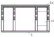
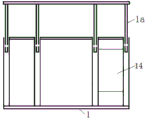
The bottom of the tent is composed of a base 1 and an auxiliary base 1a (as shown in figure 7), the framework of the base 1 is composed of cross rods and vertical rods, wherein the vertical rods are hollow, the auxiliary base 1a can be retracted into the base 1, and can be extended out when needed (as shown in figure 8), so that the area of the base of the tent is increased.
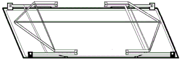
The two groups of supporting frameworks 2 are composed of an upper part and a lower part, the upper part is in an A shape, the lower part is in an H shape, the middle part is connected through a connecting joint 4 (as shown in figure 6), the upper part and the lower part can be folded together by taking the connecting joint 4 as a central point (as shown in figure 3), four feet of the two groups of supporting frameworks 2 are respectively fixed at two ends of a tent base 1 through connecting pieces and can be laid down and erected at ninety degrees; the supporting framework adopts a folding structure, so that the height inside the tent can reach a very comfortable height.
The air pressure support rods are composed of four groups of 31, 32, 33 and 34, two ends of the four groups of air pressure rods are respectively fixed on four feet of the tent base 1 and the two groups of support frameworks 2, and the two groups of support frameworks can be supported by 90 degrees under the action of the air pressure support rods.
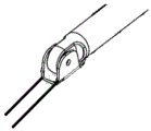
The connecting joints 4 (as shown in fig. 6) have six groups, wherein four groups of connecting joints 4 are respectively connected with the upper part and the lower part of the two groups of supporting frameworks 2, and the upper part and the lower part of the two groups of supporting frameworks 2 can be folded by taking the connecting joints 4 as central points.
The stay cord is by 51, 52, 53, 54, four are constituteed, four stay cords one end are fixed in respectively on four feet of 2a, 2b, 2c, 2d of support chassis 2, another end passes the hole of U type buckle 5e respectively, finally four stay cords pass and turn round together behind the hole of U type buckle 5e and constitute a big stay cord 5a, can reach through drawing enlarged stay cord 5a and fall or prop up support chassis 2 to reach the convenient function of opening fast or closed tent.
Two ends of the cross rod 6 are respectively fixed at the top ends of the two groups of supporting frameworks 2 through connecting joints 4 (as shown in figure 5).
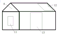
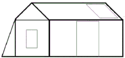
The tarpaulin 8 covers the outside of the supporting framework 2, and a window 11, a skylight 12 and a doorway 13 are arranged on the tarpaulin 8 (as shown in figure 4).
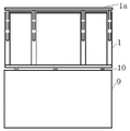
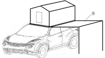
The edge of one side of the roof tent top cover 9 is connected with the edge of one side of the base 1 through the hinge 10, when the roof tent top cover 9 is opened to 180 degrees, the roof tent top cover can be used as a car roof by being matched with the stay bar (as shown in figure 11), and the functionality of the roof tent top cover is greatly increased.
The base access 14 is arranged at one end of the base 1 (as shown in fig. 7), the base access 14 is right opposite to an automobile skylight, and people can get in and out the tent from the automobile skylight, so that the functionality and the practicability of the tent are improved.
Drawings
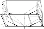
Fig. 1 is a schematic structural view of the overall framework of the present invention, fig. 2 is a schematic view of each part in the schematic structural view of the present invention, and fig. 3 is a schematic structural view of the folded two sets of supporting frameworks of the present invention; fig. 4 is a schematic view of the three-dimensional structure of the utility model covered with tarpaulin, fig. 5 is an enlarged structure of the cross bar and the connecting joint of the supporting frame, fig. 6 is an enlarged structure of the upper and lower connecting joints of the supporting frame, fig. 7 is an enlarged structure of the two bases of the utility model contracted together, fig. 8 is an enlarged structure of the two bases of the utility model after being stretched and enlarged, fig. 9 is a schematic view of the three-dimensional structure of the tarpaulin covered after being stretched and enlarged, fig. 10 is a schematic view of the structure of the tent top cover connected with the base, fig. 11 is a schematic view of the structure of the tent top cover installed on the roof and opened as the side awning of the automobile;
numerical description: the multifunctional tent comprises a base, an auxiliary base 1a, a supporting framework 2, supporting frameworks 2a, 2b, 2c and 2d, four feet of two groups of supporting frameworks 31, 32, 33 and 34 respectively, an air pressure supporting rod 4, a connecting joint 51, 52, 53 and 54 respectively, a pull rope 5a, a large pull rope 5a, a U-shaped buckle 5e, 5f and 5g, a cross rod 6, a connecting joint 7, tarpaulin 8, a tent top cover 9, a hinge 10, a window 11, a skylight 12, a doorway 13 and a base doorway 14.
Detailed Description
The present invention will be described in detail below with reference to the accompanying drawings and specific embodiments, which include but are not limited to the following examples.
The structure schematic diagram (as shown in fig. 1) of the integral framework of the novel pitched roof tent in the embodiment is that the base is composed of a base 1 and an auxiliary base 1 a; the two groups of supporting frameworks are composed of an upper part and a lower part, the upper part is in an A shape, the lower part is in an H shape, the middle part is connected through a connecting joint 4 (as shown in figure 6), the upper part and the lower part can be folded together by taking the connecting joint 4 as a central point (as shown in figure 3), and four feet of the two groups of supporting frameworks 2 are respectively fixed at two ends of a tent base 1 through connecting pieces; two ends of the four groups of air pressure supporting rods are respectively fixed on four feet of the tent base 1 and the two groups of supporting frameworks 2; one ends of the four groups of pull ropes are respectively fixed on the four feet 2a, 2b, 2c and 2d of the supporting framework 2, the other ends of the four groups of pull ropes respectively penetrate through the holes of the U-shaped buckle 5e, and finally the four pull ropes are twisted together after penetrating through the holes of the U-shaped buckle 5e to form a large pull rope 5 a; two ends of the cross bar 6 are respectively fixed at the top ends of the two groups of supporting frameworks 2 through connecting joints 4 (as shown in figure 5); the tarpaulin 8 covers the outside of the supporting framework 2, and a window 11, a skylight 12 and a doorway 13 (shown in figure 4) are arranged on the tarpaulin 8; the edge of one side of the top cover 9 of the car roof tent is connected with the edge of one side of the base 1 through a flap 10 (as shown in figure 11); the base entrance 14 is arranged at one end of the base 1 (as shown in fig. 7), and the base entrance 14 is opposite to the automobile skylight; when the novel pitched roof tent is normally used, the framework is in a supported state (as shown in figure 2), when the novel pitched roof tent needs to be closed, only the large pull rope 5a needs to be pulled, the two groups of supporting frameworks are folded (as shown in figure 3), and then the pull rope 5a is fastened; when the tent needs to be opened, the two groups of supporting frameworks are supported under the action of the air pressure rod by only loosening the pull rope 5a, so that the tent can be normally used, and the state diagram of the tent during normal use is shown (as shown in fig. 4); if the using area of the base needs to be increased, only the auxiliary base 1a needs to be pulled out (as shown in fig. 8), and the state diagram of the auxiliary base 1a when the auxiliary base is pulled out for use (as shown in fig. 9); after the tent top cover 9 is opened, the distribution stay bar can be used as a side awning of an automobile (as shown in figure 11); the novel pitched roof tent is provided with a doorway 13 and a base doorway 14, and the novel pitched roof tent can enter and exit from different openings according to the needs of people.
Compared with the prior art, the utility model has the advantages that: 1. the utility model adopts an oblique top structure, and the rainwater can flow away rapidly when raining heavily. 2. The appearance looks like a small house with an inclined top, and the appearance is attractive. 3. Sitting in the tent, two sets of support frameworks can be used as the back, have increased the travelling comfort. 4. The ladder stand is provided with the two inlets and the two outlets, so that the ladder stand can directly enter from the inlet and the outlet of the base when raining outdoors, and the ladder stand is prevented from being drenched by rain. 5. The tent top cover can be used as a side awning of an automobile after being opened by matching with the stay bar, and the trouble of additionally purchasing and installing the side awning of the automobile is avoided. 6. The tent can be opened and closed by pulling and releasing the pull rope, and the convenient and fast functions are achieved. 7. The supporting framework adopts a folding structure, so that the internal height of the tent can be very comfortable.
Above-mentioned embodiment is only the utility model discloses an embodiment is not used for the restriction the utility model discloses self, under above-mentioned structural design's prerequisite, even for solving same technical problem make some insubstantial changes or moist look on the utility model discloses, or replace equally, or rely on the utility model discloses a main part thought carries out some meaningless expansions, its technical scheme's that adopts essence still with the utility model discloses unanimously, also should be in the protection scope of the utility model.
Claims (7)
1. The utility model provides a novel oblique top roof tent which characterized in that: the device comprises a base (1), an auxiliary base (1a), two groups of supporting frameworks (2), air pressure supporting rods (31), (32), (33) and (34), a connecting joint (4), pull ropes (51), (52), (53) and (54), a large pull rope (5 a), a U-shaped buckle (5 e), a cross bar (6), tarpaulin (8), a roof tent top cover (9), a loose leaf (10), a window (11), a skylight (12), a doorway (13) and a base access opening (14); the bottom of the tent consists of a base (1) and an auxiliary base (1 a); the two groups of supporting frameworks (2) are composed of an upper part and a lower part, the upper part is in an A shape, the lower part is in an H shape, the middle part is connected through a connecting joint (4), the two groups of supporting frameworks (2) are respectively fixed at two ends of the tent base (1) through connecting pieces and can be laid down and erected for ninety degrees; the air pressure support rods are four in number; the first connecting joint (4) comprises six groups, the first pulling rope comprises 4 pulling ropes, the first large pulling rope (5 a) comprises one pulling rope, one end of each pulling rope is fixed with the four feet of the supporting framework (2), and the other end of each pulling rope penetrates through a hole of the U-shaped buckle; the both ends of horizontal pole (6) are fixed in the top of support chassis (2) through connecting joint (4), tarpaulin (8) cover in the outside of support chassis (2), are equipped with window (11) on tarpaulin (8), skylight (12) and gate (13), the border on one side of roof tent top cap (9) is passed through loose leaf (10) with the border on one side of base (1) and is connected, and when roof tent top cap (9) were opened and are 180 degrees, join in marriage the vaulting pole and can regard as car side canopy to use, the one end at base (1) is established in base access & exit (14).
2. The new pent roof tent of claim 1, characterized in that: the tent is characterized in that the bottom of the tent is composed of a base (1) and an auxiliary base (1a), a framework of the base (1) is composed of a cross rod and a vertical rod, the vertical rod is hollow, the auxiliary base (1a) can be retracted into the base (1) and can be extended out when needed, and a base inlet and outlet (14) is further arranged on the base (1).
3. The new pent roof tent of claim 1, characterized in that: two sets of support frameworks (2) are become by upper and lower two parts, and the upper portion is "A" shape, and the lower part is "H" shape, and the centre forms through connecting joint (4) connection, and upper portion and lower part can use connecting joint (4) to fold together as the central point, and four feet of two sets of support frameworks (2) are fixed in the both ends of tent base (1) respectively through the connecting piece, and can fall and erect ninety degrees.
4. The new pent roof tent of claim 1, characterized in that: the air pressure support rods are composed of four groups (31), (32), (33) and (34), and two ends of the four groups of air pressure rods are respectively fixed on four feet of the tent base (1) and the support framework (2).
5. The new pent roof tent of claim 1, characterized in that: the connecting joints (4) are composed of six groups, wherein four groups of connecting joints (4) are respectively connected with the upper parts and the lower parts of the two groups of supporting frameworks (2), and the upper parts and the lower parts of the two groups of supporting frameworks (2) can be folded by taking the connecting joints (4) as central points.
6. The new pent roof tent of claim 1, characterized in that: the pull ropes are composed of four pull ropes (51), (52), (53) and (54), one ends of the four pull ropes are respectively fixed on four feet of (2 a), (2 b), (2 c) and (2 d) of the supporting framework (2), the other ends of the four pull ropes respectively penetrate through holes of the U-shaped buckle (5 e), and finally the four pull ropes are twisted together after penetrating through the holes of the U-shaped buckle (5 e) to form a large pull rope (5 a).
7. The new pent roof tent of claim 1, characterized in that: the two ends of the cross rod (6) are respectively fixed at the top ends of the two groups of supporting frameworks (2) through the connecting joints (4).
Priority Applications (1)
| Application Number | Priority Date | Filing Date | Title |
|---|---|---|---|
| CN201920877506.9U CN210768088U (en) | 2019-06-12 | 2019-06-12 | Novel inclined top roof tent |
Applications Claiming Priority (1)
| Application Number | Priority Date | Filing Date | Title |
|---|---|---|---|
| CN201920877506.9U CN210768088U (en) | 2019-06-12 | 2019-06-12 | Novel inclined top roof tent |
Publications (1)
| Publication Number | Publication Date |
|---|---|
| CN210768088U true CN210768088U (en) | 2020-06-16 |
Family
ID=71039019
Family Applications (1)
| Application Number | Title | Priority Date | Filing Date |
|---|---|---|---|
| CN201920877506.9U Expired - Fee Related CN210768088U (en) | 2019-06-12 | 2019-06-12 | Novel inclined top roof tent |
Country Status (1)
| Country | Link |
|---|---|
| CN (1) | CN210768088U (en) |
Cited By (3)
| Publication number | Priority date | Publication date | Assignee | Title |
|---|---|---|---|---|
| CN114150926A (en) * | 2021-12-03 | 2022-03-08 | 秋野地(厦门)户外装备科技有限公司 | Automatic folding type car roof tent |
| CN114165101A (en) * | 2021-12-27 | 2022-03-11 | 广州市凯途环保科技有限公司 | Camp tent on roof of automobile |
| CN114541861A (en) * | 2022-02-16 | 2022-05-27 | 厦门友一金属有限公司 | Vehicle-mounted floor type semi-automatic tent |
-
2019
- 2019-06-12 CN CN201920877506.9U patent/CN210768088U/en not_active Expired - Fee Related
Cited By (3)
| Publication number | Priority date | Publication date | Assignee | Title |
|---|---|---|---|---|
| CN114150926A (en) * | 2021-12-03 | 2022-03-08 | 秋野地(厦门)户外装备科技有限公司 | Automatic folding type car roof tent |
| CN114165101A (en) * | 2021-12-27 | 2022-03-11 | 广州市凯途环保科技有限公司 | Camp tent on roof of automobile |
| CN114541861A (en) * | 2022-02-16 | 2022-05-27 | 厦门友一金属有限公司 | Vehicle-mounted floor type semi-automatic tent |
Similar Documents
| Publication | Publication Date | Title |
|---|---|---|
| CN2637641Y (en) | Portable folding mat shelter | |
| CN206279870U (en) | A kind of tent frame rod with eaves | |
| KR101215137B1 (en) | Parasol with composite strut structure | |
| CN210976827U (en) | Portable collapsible yurt structure | |
| CN209324126U (en) | A foldable canopy tent | |
| CN202401821U (en) | Double-purpose tent | |
| CN114165101A (en) | Camp tent on roof of automobile | |
| CN214786496U (en) | Inclined tent frame | |
| CN113216733A (en) | Tilting folding tent framework | |
| KR20120051467A (en) | Fly of tent for fishing | |
| CN215055941U (en) | Manually deploy folding roof tent with side canopy | |
| CN224200350U (en) | Tent with extended eave | |
| CN219196908U (en) | Multipurpose awning and hammock adopting same | |
| CN223135798U (en) | A simple folding umbrella tent | |
| CN212507680U (en) | A tent that is convenient to increase the sunshade and waterproof area | |
| CN221073729U (en) | Folding tent support | |
| CN222667806U (en) | Multifunctional tent | |
| CN216840934U (en) | Novel tent | |
| CN218493276U (en) | Tent | |
| CN206128836U (en) | Eaves structure of tent | |
| CN221002206U (en) | House type tent | |
| CN205012752U (en) | Take cool covering or awning on a car, boat, etc. of side covering or awning on a car, boat, etc. and eave | |
| CN220469528U (en) | Single-rod combined folding framework and tent | |
| CN205990816U (en) | It is provided with the portable awning of movable pedestal | |
| CN219012140U (en) | Tunnel type tent with cross rod structure |
Legal Events
| Date | Code | Title | Description |
|---|---|---|---|
| GR01 | Patent grant | ||
| GR01 | Patent grant | ||
| CF01 | Termination of patent right due to non-payment of annual fee |
Granted publication date: 20200616 |
|
| CF01 | Termination of patent right due to non-payment of annual fee |