CN210758190U - Friction cutting structure - Google Patents
Friction cutting structure Download PDFInfo
- Publication number
- CN210758190U CN210758190U CN201921596817.4U CN201921596817U CN210758190U CN 210758190 U CN210758190 U CN 210758190U CN 201921596817 U CN201921596817 U CN 201921596817U CN 210758190 U CN210758190 U CN 210758190U
- Authority
- CN
- China
- Prior art keywords
- blade
- cutting
- lower shell
- wear
- gasket
- Prior art date
- Legal status (The legal status is an assumption and is not a legal conclusion. Google has not performed a legal analysis and makes no representation as to the accuracy of the status listed.)
- Expired - Fee Related
Links
- 230000005540 biological transmission Effects 0.000 claims abstract description 46
- 230000007246 mechanism Effects 0.000 claims abstract description 44
- 238000001125 extrusion Methods 0.000 claims abstract description 10
- 230000033001 locomotion Effects 0.000 claims abstract description 5
- 238000005096 rolling process Methods 0.000 claims abstract description 4
- 230000003139 buffering effect Effects 0.000 claims description 7
- 239000002184 metal Substances 0.000 claims description 5
- 238000010586 diagram Methods 0.000 description 2
- 238000000034 method Methods 0.000 description 2
- 230000000149 penetrating effect Effects 0.000 description 2
- 208000027418 Wounds and injury Diseases 0.000 description 1
- 230000006378 damage Effects 0.000 description 1
- 230000000694 effects Effects 0.000 description 1
- 208000014674 injury Diseases 0.000 description 1
- 239000000463 material Substances 0.000 description 1
- 238000003825 pressing Methods 0.000 description 1
- 238000000926 separation method Methods 0.000 description 1
- 238000006467 substitution reaction Methods 0.000 description 1
Images




Landscapes
- Details Of Cutting Devices (AREA)
Abstract
The utility model discloses a friction cutting structure, which comprises a lower shell and an upper shell matched with the lower shell, wherein a group of auxiliary roller groups and a group of transmission roller groups are arranged in the lower shell, and the rolling cutting motion between the lower shell and a to-be-cut object is completed through the two groups of roller groups; the output of transmission roller train is provided with friction cutting mechanism, and the bottom lateral surface of inferior valve is provided with the deflector of a reassembling type, will treat the cutting thing direction and enter into the cutting mechanism of friction through removing the inferior valve and cut. The utility model discloses can realize tailorring the paper fast, the hand is not hindered to safety, and the cut paper is quick, simple, safe, conveniently carries than traditional paper cutter, and is small, and the blade can be used forever, and the cutting principle is realized through the friction extrusion function between circular blade and the right angle blade, and no blade point design can not have wearing and tearing blade point phenomenon, and built-in blade is safer with no blade point design, does not hinder the hand, does not hinder the desktop, safe and reliable.
Description
Technical Field
The utility model relates to a paper cutting field, concretely relates to friction cutting structure.
Background
The cutting of traditional paper or other materials generally all adopts the blade to cut, grinds the cutting edge on the blade, when the mode that adopts the cutting edge cutting cut the paper on the plane, the desktop can be damaged to the cutting edge, produces the mar, and the cutting edge also can bring unexpected injury for the user simultaneously, and the cutting edge also easily wears out after using for a long time in addition, needs often polish, unusual inconvenience.
Disclosure of Invention
The utility model aims to solve the technical problem that a friction cutting structure adopts a brand-new friction extrusion cutting mode, can be effectual a great deal of not enough among the solution prior art.
The utility model discloses a realize through following technical scheme: the cutting machine comprises a lower shell and an upper shell which is matched with the lower shell, wherein a group of auxiliary roller groups and a group of transmission roller groups are arranged in the lower shell, and the rolling cutting motion between the lower shell and a to-be-cut object is completed through the two groups of roller groups; the output end of the transmission roller group is provided with a friction cutting mechanism, the outer side surface of the bottom of the lower shell is provided with a detachable guide plate, and the object to be cut is guided into the friction cutting mechanism to be cut by moving the lower shell
According to a preferable technical scheme, the transmission roller group comprises a hollow power shaft, a power gear is mounted outside the power shaft, a first fixed shaft penetrates through the middle of the power shaft and extends out of two sides of the power shaft, and a transmission roller is mounted on each of two sides of the extending end of the first fixed shaft; the middle of each transmission roller is provided with a first shaft sleeve, each first fixed shaft penetrates through the corresponding first shaft sleeve and the corresponding transmission roller and extends out of the corresponding transmission roller, the extending end of each first fixed shaft is sleeved with a first wear-resistant gasket, the whole transmission roller set is fixedly arranged on a first support on the lower shell, and the first wear-resistant gaskets are supported and fixed in first U-shaped grooves of the first supports. According to the preferable technical scheme, an intermediate transmission mechanism is arranged between the transmission roller group and the friction cutting mechanism and comprises a connecting gear, a second fixed shaft and a second wear-resistant gasket, the second fixed shaft penetrates through the connecting gear and extends out of two sides of the connecting gear, the whole intermediate transmission mechanism is installed on a second support on the lower shell, the second wear-resistant gasket is installed at the extending end of the second fixed shaft and is supported and fixed in a second U-shaped groove of the second support, and the connecting gear is in meshing transmission with the power gear.
As the preferable technical scheme, the friction cutting mechanism comprises a blade gear, a third fixed shaft, a third wear-resistant gasket, a wear-resistant positioning gasket and a right-angle cutting blade, the wear-resistant positioning gasket is inserted on a convex part on the right-angle cutting blade, a first shaft hole is arranged in the middle of the convex part, the cutter blade is arranged right opposite to a second shaft hole on a wear-resistant positioning gasket, a circular blade is arranged on one side of a blade gear, a third fixing shaft penetrates through the blade gear, the wear-resistant positioning gasket and a right-angle cutting blade and is arranged in a third U-shaped groove on a third support, a third wear-resistant gasket is arranged on the third support in a supporting mode, the third fixing shaft penetrates through the third wear-resistant gasket, one side of the circular blade is in friction extrusion contact with the right-angle cutting blade, the blade gear is in meshing transmission with a connecting gear of an intermediate transmission mechanism, the connecting gear rotates to drive the circular blade to rotate so as to extrude and cut paper relative to the right-angle cutting blade.
As the preferred technical scheme, the friction cutting mechanism is also provided with an upper limiting mechanism, a lower limiting mechanism and a buffering yielding mechanism.
As the preferred technical scheme, upper and lower limiting mechanism includes an upper limiting shim and a lower limiting shim, and lower limiting shim fixed mounting is in the bottom of upper limiting shim, and upper limiting shim one side is through screw fixed mounting on the boss of inferior valve, and right angle cutting blade is located the bottom of lower limiting shim, compresses tightly right angle cutting blade through lower limiting shim and restricts its top and bottom.
According to a preferable technical scheme, the buffering yielding mechanism comprises a gap adjusting rod, the gap adjusting rod is a metal elastic thin rod, one end of the gap adjusting rod is inserted into a small hole of the right-angle cutting blade, the other end of the gap adjusting rod is clamped on a fixed convex column on the lower shell, different paper thicknesses are adapted through the gap adjusting rod, and then a gap between the right-angle cutting blade and the circular blade is adjusted.
As the preferred technical scheme, the guide plate is detachably mounted in the bottom buckling position of the right-angle cutting blade through a buckle, the guide plate extends out of the lower end face of the lower shell, a paper guide cavity is formed between the convex face of the guide plate and the bottom face of the lower shell, and an inclined guide part is arranged on one side, located on the paper guide cavity, of the guide plate.
As a preferable technical scheme, the auxiliary roller group comprises two auxiliary rollers, a connecting roller sleeve, a second shaft sleeve, a fourth fixing shaft and a fourth wear-resistant gasket, the fourth fixing shaft penetrates through the connecting roller sleeve and penetrates through the second shaft sleeve to extend out of the auxiliary rollers, the second shaft sleeve is embedded in the auxiliary rollers, and the outer portion of the fourth fixing shaft is fixedly supported in a fourth U-shaped groove in a fourth support through the fourth wear-resistant gasket.
As the preferred technical scheme, the lower shell and the upper shell are fixedly assembled through screws, the lower shell is provided with a wheel groove for the roller to pass through, and the part of the roller passing through the wheel groove extends out of the bottom of the lower shell.
The utility model has the advantages that: the utility model can realize fast cutting paper, is safe and does not hurt hands, and can cut paper fast, simply and safely, and is more convenient to carry and smaller than the traditional paper cutter; the blade can be used permanently, and the cutting principle is realized by the friction extrusion function between the circular blade and the right-angle blade; the design of no blade edge can not have wearing and tearing blade edge phenomenon, and built-in blade is safer with no blade edge design, does not hinder the hand, does not hinder the desktop, safe and reliable.
The paper cutting machine is convenient and practical, and is necessary for students, families, offices and gift packages, so that the cutting principle of the traditional paper is overturned; the operation is simple, the hand is safe and not hurt, the paper can be used by children over 3 years old, and the paper cutting is relieved; the paper cutter can cut paper with different thicknesses, automatically adjusts cutting gaps of the paper cutter, is self-adaptive to cutting of the thickness of the paper, can cut lines in any shape, and does not have burrs or burrs on the cut paper.
Drawings
In order to more clearly illustrate the embodiments of the present invention or the technical solutions in the prior art, the drawings used in the description of the embodiments or the prior art will be briefly described below, it is obvious that the drawings in the following description are only some embodiments of the present invention, and for those skilled in the art, other drawings can be obtained according to these drawings without creative efforts.
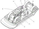
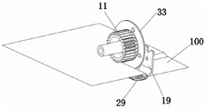
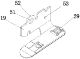
FIG. 1 is an exploded view of the present invention; FIG. 2 is a schematic view of the overall assembly of the present invention; fig. 3 is a cutting schematic diagram of the friction cutting mechanism of the present invention; fig. 4 is a schematic cutting view of another view angle of the friction cutting mechanism of the present invention; fig. 5 is an assembly view of the right angle cutting blade and the guide plate of the present invention; fig. 6 is an assembly schematic view of the upper and lower limiting mechanisms of the present invention; fig. 7 is an assembly diagram of the buffering and yielding mechanism and the right-angle cutting blade of the present invention.
Detailed Description
All of the features disclosed in this specification, or all of the steps in any method or process so disclosed, may be combined in any combination, except combinations of features and/or steps that are mutually exclusive.
Any feature disclosed in this specification (including any accompanying claims, abstract and drawings), may be replaced by alternative features serving equivalent or similar purposes, unless expressly stated otherwise. That is, unless expressly stated otherwise, each feature is only an example of a generic series of equivalent or similar features.
In the description of the present invention, it is to be understood that the terms "one end", "the other end", "the outside", "upper", "inside", "horizontal", "coaxial", "central", "end", "length", "outer end", etc. indicate orientations or positional relationships based on those shown in the drawings, and are only for convenience of description and simplicity of description, and do not indicate or imply that the device or element referred to must have a particular orientation, be constructed and operated in a particular orientation, and therefore, should not be construed as limiting the present invention.
Furthermore, in the description of the present invention, "a plurality" means at least two, e.g., two, three, etc., unless specifically limited otherwise.
The use of terms herein such as "upper," "above," "lower," "below," and the like in describing relative spatial positions is for the purpose of facilitating description to describe one element or feature's relationship to another element or feature as illustrated in the figures. The spatially relative positional terms may be intended to encompass different orientations of the device in use or operation in addition to the orientation depicted in the figures. For example, if the device in the figures is turned over, elements described as "below" or "beneath" other elements or features would then be oriented "above" the other elements or features. Thus, the exemplary term "below" can encompass both an orientation of above and below. The device may be otherwise oriented (rotated 90 degrees or at other orientations) and the spatially relative descriptors used herein interpreted accordingly.
In the present invention, unless otherwise explicitly specified or limited, the terms "set", "coupled", "connected", "penetrating", "plugging", and the like are to be understood in a broad sense, and may be, for example, fixedly connected, detachably connected, or integrated; can be mechanically or electrically connected; they may be directly connected or indirectly connected through intervening media, or they may be connected internally or in any other suitable relationship, unless expressly stated otherwise. The specific meaning of the above terms in the present invention can be understood according to specific situations by those skilled in the art.
As shown in fig. 1 and 2, the paper cutting device comprises a lower shell 28 and an upper shell 1 which is installed in a matching way, wherein a group of auxiliary roller groups and a group of transmission roller groups are arranged in the lower shell 28, and the rolling cutting movement between the lower shell and the paper is completed through the two groups of roller groups; the output end of the transmission roller group is provided with a friction cutting mechanism, the outer side surface of the bottom of the lower shell is provided with a detachable guide plate 29, and the paper to be cut is guided to enter the friction cutting mechanism for cutting by moving the lower shell 28.
As shown in fig. 1, the transmission roller group comprises a hollow power shaft 2, a power gear 32 is arranged outside the power shaft 2, a first fixed shaft 3 is arranged in the middle of the power shaft 2 in a penetrating way, the first fixed shaft 3 penetrates through the power shaft 2 to extend out of two sides, and a transmission roller 5 is respectively arranged on two sides of the extending end of the first fixed shaft; a first shaft sleeve 4 is arranged in the middle of each transmission roller 5, each first fixing shaft 3 penetrates through the corresponding first shaft sleeve 4 and the corresponding transmission roller 5 and extends out of the corresponding transmission roller, a first wear-resistant gasket 6 is sleeved at the extending end of each first fixing shaft 3, the whole transmission roller set is fixedly arranged on a first support on the lower shell 28, and the first wear-resistant gaskets 6 are fixedly supported in first U-shaped grooves of the first support. An intermediate transmission mechanism is arranged between the transmission roller group and the friction cutting mechanism, the intermediate transmission mechanism comprises a connecting gear 14, a second fixed shaft 8 and a second wear-resistant gasket 7, the second fixed shaft 8 penetrates through the connecting gear 14 and extends out of two sides of the connecting gear 14, the whole intermediate transmission mechanism is installed on a second support on the lower shell, the second wear-resistant gasket 7 is installed at the extending end of the second fixed shaft and is supported and fixed in a second U-shaped groove of the second support, and the connecting gear 14 is in meshing transmission with the power gear 32.
As shown in fig. 1, 3 and 4, the friction cutting mechanism comprises a blade gear 11, a third fixed shaft 9, a third wear-resistant pad 10, a wear-resistant positioning pad 16 and a right-angle cutting blade 19, the wear-resistant positioning pad 16 is inserted into a raised part 52 on the right-angle cutting blade 19, the raised part 52 is provided with a first shaft hole 51 in the middle and is arranged opposite to a second shaft hole on the wear-resistant positioning pad 16, a circular blade 33 is arranged at one side of the blade gear 11, the third fixed shaft penetrates through the blade gear 11, the wear-resistant positioning pad 16 and the right-angle cutting blade 19 and is arranged in a third U-shaped groove on a third bracket, the third bracket supports and is provided with a third wear-resistant pad 10, the third fixed shaft 9 penetrates through the third wear-resistant pad 10, one side of the circular blade 33 is in friction pressing contact with the right-angle cutting blade 19, the blade gear 11 is, the circular blade 33 is rotated by the rotation of the connecting gear 14 to press and cut the paper against the right angle cutting blade 19.
Wherein, the friction cutting mechanism is also provided with an upper and lower limiting mechanism and a buffering yielding mechanism.
In this embodiment, as shown in fig. 6, the upper and lower limiting mechanism includes an upper limiting shim 17 and a lower limiting shim 20, the lower limiting shim 20 is fixedly mounted at the bottom of the upper limiting shim 17, one side of the upper limiting shim 17 is fixedly mounted on the boss of the lower shell 28 through a screw, the right-angle cutting blade 19 is located at the bottom of the lower limiting shim 29, the lower limiting shim 20 presses the right-angle cutting blade 19 to limit the upper and lower surfaces thereof, and in addition, the third fixing shaft 9 can also play a role in limiting the up-and-down movement of the right-angle cutting blade 19.
As shown in fig. 7, the buffering and yielding mechanism includes a gap adjusting rod 18, the gap adjusting rod 18 is a metal elastic thin rod, one end of the metal elastic thin rod is inserted into the small hole 53 of the right-angle cutting blade 19, the other end of the metal elastic thin rod is clamped on the fixed convex column 31 on the lower shell 28, the gap adjusting rod 18 is adapted to different paper thicknesses, and then the gap between the right-angle cutting blade and the circular blade is adjusted.
As shown in fig. 5, the guiding plate 29 is detachably mounted in the bottom buckling position of the right angle cutting blade 19 by a buckle, the guiding plate 29 extends out of the lower end surface of the lower shell, a paper guiding cavity is formed between the convex surface of the guiding plate 29 and the bottom surface of the lower shell, and an inclined guiding part is arranged on one side of the guiding plate 29, which is positioned at the paper guiding cavity.
The auxiliary roller group comprises two auxiliary rollers 26, a connecting roller sleeve 23, a second shaft sleeve 25, a fourth fixing shaft 24 and a fourth wear-resistant gasket 21, the fourth fixing shaft 24 penetrates through the connecting roller sleeve 23 and penetrates through the second shaft sleeve 25 and the auxiliary rollers 26 to extend out, the second shaft sleeve 25 is arranged in the auxiliary rollers 26, the outer portion of the fourth fixing shaft 24 is fixedly supported in a fourth U-shaped groove in a fourth support through the fourth wear-resistant gasket 21, the lower shell 28 and the upper shell are fixedly assembled through screws, a roller groove for the roller to penetrate through is formed in the lower shell, and the roller penetrates through the roller groove and partially extends out of the bottom of the lower shell.
The working principle is as follows: the upper shell is grasped by a hand, the middle part of the upper shell is aligned with the position of paper to be cut, the paper cutter is lightly pressed to be pushed forwards, the transmission roller rotates and rolls to drive the power gear, then the power is transmitted to the blade gear by the connecting gear, and the cutting principle is realized by utilizing the rotating friction extrusion between the right-angle cutting blade and the circular blade.
The paper passes through the guide effect of deflector, can send into the contact opening portion of circular blade and right angle cutting blade to the paper smoothly, because the rotation of circular blade can produce the friction with the right angle cutting blade, frictional force can be to the paper cutting separation. The clearance adjusting rod and the elastic force adjusting design mechanism can automatically adjust the extrusion force between the circular blade and the right-angle cutting blade,
self-adaptive extrusion force can realize cutting the paper of different thickness, so two kinds of design utility model of circular blade and right angle cutting blade accessible frictional force and extrusion force realize the paper cutting that can cut different thickness smoothly, as shown in fig. 3 and 4.
The auxiliary roller plays a role in assisting in balancing and pushing the paper cutter. The first shaft sleeve plays a role in reducing the friction force between the first fixed shaft and the transmission roller, so that the transmission roller can slide and roll more smoothly.
When paper with different thicknesses passes through the circular blade and the right-angle cutting blade, the gap adjusting rod can self-adaptively send out resilience force, and the wear-resistant positioning gasket can automatically adjust the gap between the circular blade and the right-angle cutting blade under the action of the resilience force of the gap adjusting rod so as to cut the paper with different thicknesses; the guide plate is used for guiding paper to smoothly enter the contact opening part of the circular blade and the right-angle cutting blade, the guide plate is an external part and can be disassembled and replaced, and convenience is brought to users if the stapler needle is replaced.
The utility model has the advantages that: the utility model can realize fast cutting paper, is safe and does not hurt hands, and can cut paper fast, simply and safely, and is more convenient to carry and smaller than the traditional paper cutter; the blade can be used permanently, and the cutting principle is realized by the friction extrusion function between the circular blade and the right-angle blade; the design of no blade edge can not have wearing and tearing blade edge phenomenon, and built-in blade is safer with no blade edge design, does not hinder the hand, does not hinder the desktop, safe and reliable.
The paper cutting machine is convenient and practical, and is necessary for students, families, offices and gift packages, so that the cutting principle of the traditional paper is overturned; the operation is simple, the hand is safe and not hurt, the paper can be used by children over 3 years old, and the paper cutting is relieved;
the paper cutter can cut paper with different thicknesses, automatically adjusts cutting gaps of the paper cutter, is self-adaptive to cutting of the thickness of the paper, can cut lines in any shape, and does not have burrs or burrs on the cut paper.
The above description is only for the specific embodiments of the present invention, but the scope of the present invention is not limited thereto, and any changes or substitutions that are not thought of through the creative work should be covered within the scope of the present invention. Therefore, the protection scope of the present invention should be subject to the protection scope defined by the claims.
Claims (10)
1. A friction cutting structure characterized by: the cutting machine comprises a lower shell and an upper shell which is matched with the lower shell, wherein a group of auxiliary roller groups and a group of transmission roller groups are arranged in the lower shell, and the rolling cutting motion between the lower shell and a to-be-cut object is completed through the two groups of roller groups; the output of transmission roller train is provided with friction cutting mechanism, and the bottom lateral surface of inferior valve is provided with the deflector of a reassembling type, will treat the cutting thing direction and enter into the cutting mechanism of friction through removing the inferior valve and cut.
2. A frictional cutting structure as set forth in claim 1, wherein: the transmission roller group comprises a hollow power shaft, a power gear is arranged outside the power shaft, a first fixed shaft penetrates through the middle of the power shaft, the first fixed shaft penetrates through the power shaft to extend out of two sides, and two sides of the extending end of the first fixed shaft are respectively provided with a transmission roller; the middle of each transmission roller is provided with a first shaft sleeve, each first fixed shaft penetrates through the corresponding first shaft sleeve and the corresponding transmission roller and extends out of the corresponding transmission roller, the extending end of each first fixed shaft is sleeved with a first wear-resistant gasket, the whole transmission roller set is fixedly arranged on a first support on the lower shell, and the first wear-resistant gaskets are supported and fixed in first U-shaped grooves of the first supports.
3. A frictional cutting structure as set forth in claim 1, wherein: an intermediate transmission mechanism is arranged between the transmission roller set and the friction cutting mechanism and comprises a connecting gear, a second fixed shaft and a second wear-resistant gasket, the second fixed shaft penetrates through the connecting gear and extends out of two sides of the connecting gear, the whole intermediate transmission mechanism is installed on a second support on the lower shell, the second wear-resistant gasket is installed at the extending end of the second fixed shaft and is supported and fixed in a second U-shaped groove of the second support, and the connecting gear is in meshing transmission with the power gear.
4. A frictional cutting structure as set forth in claim 1, wherein: the friction cutting mechanism comprises a blade gear, a third fixed shaft, a third wear-resistant gasket, a wear-resistant positioning gasket and a right-angle cutting blade, the wear-resistant positioning gasket is inserted on a convex part on the right-angle cutting blade, a first shaft hole is arranged in the middle of the convex part, the cutter blade is arranged right opposite to a second shaft hole on a wear-resistant positioning gasket, a circular blade is arranged on one side of a blade gear, a third fixing shaft penetrates through the blade gear, the wear-resistant positioning gasket and a right-angle cutting blade and is arranged in a third U-shaped groove on a third support, a third wear-resistant gasket is arranged on the third support in a supporting mode, the third fixing shaft penetrates through the third wear-resistant gasket, one side of the circular blade is in friction extrusion contact with the right-angle cutting blade, the blade gear is in meshing transmission with a connecting gear of an intermediate transmission mechanism, the connecting gear rotates to drive the circular blade to rotate so as to extrude and cut paper relative to the right-angle cutting blade.
5. A frictional cutting structure as set forth in claim 1, wherein: the friction cutting mechanism is also provided with an upper limiting mechanism, a lower limiting mechanism and a buffering yielding mechanism.
6. A frictional cutting structure as set forth in claim 5, wherein: stop gear includes a last spacing gasket and a lower spacing gasket, and spacing gasket fixed mounting is down in the bottom of last spacing gasket, go up spacing gasket one side through screw fixed mounting on the boss of inferior valve, right angle cutting blade is located the bottom of spacing gasket down, compresses tightly right angle cutting blade through lower spacing gasket and restricts its top and bottom.
7. A frictional cutting structure as set forth in claim 5, wherein: the buffering yielding mechanism comprises a gap adjusting rod which is a metal elastic thin rod, one end of the gap adjusting rod is inserted into a small hole of the right-angle cutting blade, the other end of the gap adjusting rod is clamped on the fixed convex column on the lower shell, different paper thicknesses are adapted through the gap adjusting rod, and then the gap between the right-angle cutting blade and the circular blade is adjusted.
8. A frictional cutting structure as set forth in claim 1, wherein: the guide plate is installed in the bottom buckling position of the right-angle cutting blade through the buckle in a detachable mode, the guide plate extends out of the lower end face of the lower shell, a paper guide cavity is formed between the protruding face of the guide plate and the bottom face of the lower shell, and an inclined guide portion is arranged on one side, located on the paper guide cavity, of the guide plate.
9. A frictional cutting structure as set forth in claim 1, wherein: the auxiliary roller group comprises two auxiliary rollers, a connecting roller sleeve, a second shaft sleeve, a fourth fixing shaft and a fourth wear-resistant gasket, the fourth fixing shaft penetrates through the connecting roller sleeve and penetrates through the second shaft sleeve to extend out of the auxiliary rollers, the second shaft sleeve is sleeved in the auxiliary rollers, and the outer portion of the fourth fixing shaft is fixedly supported in a fourth U-shaped groove in a fourth support through the fourth wear-resistant gasket.
10. A frictional cutting structure as set forth in claim 1, wherein: the lower shell and the upper shell are fixedly assembled through screws, a roller groove for the roller to penetrate is formed in the lower shell, and the roller penetrates through the roller groove and partially extends out of the bottom of the lower shell.
Priority Applications (1)
| Application Number | Priority Date | Filing Date | Title |
|---|---|---|---|
| CN201921596817.4U CN210758190U (en) | 2019-09-24 | 2019-09-24 | Friction cutting structure |
Applications Claiming Priority (1)
| Application Number | Priority Date | Filing Date | Title |
|---|---|---|---|
| CN201921596817.4U CN210758190U (en) | 2019-09-24 | 2019-09-24 | Friction cutting structure |
Publications (1)
| Publication Number | Publication Date |
|---|---|
| CN210758190U true CN210758190U (en) | 2020-06-16 |
Family
ID=71048373
Family Applications (1)
| Application Number | Title | Priority Date | Filing Date |
|---|---|---|---|
| CN201921596817.4U Expired - Fee Related CN210758190U (en) | 2019-09-24 | 2019-09-24 | Friction cutting structure |
Country Status (1)
| Country | Link |
|---|---|
| CN (1) | CN210758190U (en) |
Cited By (1)
| Publication number | Priority date | Publication date | Assignee | Title |
|---|---|---|---|---|
| CN110434935A (en) * | 2019-09-24 | 2019-11-12 | 深圳市康鑫隆科技有限公司 | A kind of friction cuttings structure |
-
2019
- 2019-09-24 CN CN201921596817.4U patent/CN210758190U/en not_active Expired - Fee Related
Cited By (2)
| Publication number | Priority date | Publication date | Assignee | Title |
|---|---|---|---|---|
| CN110434935A (en) * | 2019-09-24 | 2019-11-12 | 深圳市康鑫隆科技有限公司 | A kind of friction cuttings structure |
| CN110434935B (en) * | 2019-09-24 | 2024-07-09 | 深圳市康鑫隆科技有限公司 | Friction cutting structure |
Similar Documents
| Publication | Publication Date | Title |
|---|---|---|
| EP3395514B1 (en) | Cutting device for paper-plastic bag cutting and sealing integrated machine | |
| EP2112965B1 (en) | Cutter device | |
| CN110861227B (en) | A kind of oil stone cutting equipment for bearing production | |
| CN106283440B (en) | Multi-sequin embroidery machine head and embroidery machine thereof | |
| WO2009069206A1 (en) | Portable chamfering machine | |
| CN204414224U (en) | Circle die-cutting machine cutting mechanism | |
| CN217704904U (en) | Angle cutter structure and grooving machine using same | |
| CN207875189U (en) | A kind of multi-functional paper punching binding all-in-one machine | |
| CN110434935B (en) | Friction cutting structure | |
| CN217452373U (en) | Double-cutter-head structure of intelligent cutting machine | |
| CN114475025B (en) | Paper cutting mechanism and printer core having the same | |
| CN214604768U (en) | Punching device | |
| CN217227103U (en) | Paper cutting mechanism and printer core with same | |
| CN204340402U (en) | A kind of moving blade device for mini-printer cut paper | |
| CN212191535U (en) | Rolling type hard alloy guide head saw back pressing belt device | |
| JP5592574B1 (en) | Disc blade grinding device | |
| CN201543910U (en) | Cutting machine and protective cover component thereof | |
| CN209442386U (en) | Trimmer | |
| CN202045654U (en) | Power-driven circle shearing machine | |
| CN114274599A (en) | Adjustable fabric wheel for paper separator | |
| CN202336558U (en) | Slide block device of coiling machine | |
| CN216127824U (en) | Continuous die-cutting machine for carton | |
| CN112623849A (en) | Self-adjusting hobbing cutter part | |
| CN111391012A (en) | Novel sanitary towel shaping is cut device | |
| CN222431732U (en) | A creasing mechanism for corrugated box production |
Legal Events
| Date | Code | Title | Description |
|---|---|---|---|
| GR01 | Patent grant | ||
| GR01 | Patent grant | ||
| CF01 | Termination of patent right due to non-payment of annual fee | ||
| CF01 | Termination of patent right due to non-payment of annual fee |
Granted publication date: 20200616 |