CN210756584U - Locomotive frame end shock absorber seat adds clamping apparatus - Google Patents
Locomotive frame end shock absorber seat adds clamping apparatus Download PDFInfo
- Publication number
- CN210756584U CN210756584U CN201921479282.2U CN201921479282U CN210756584U CN 210756584 U CN210756584 U CN 210756584U CN 201921479282 U CN201921479282 U CN 201921479282U CN 210756584 U CN210756584 U CN 210756584U
- Authority
- CN
- China
- Prior art keywords
- oil cylinder
- bottom plate
- shock absorber
- locomotive
- frame end
- Prior art date
- Legal status (The legal status is an assumption and is not a legal conclusion. Google has not performed a legal analysis and makes no representation as to the accuracy of the status listed.)
- Active
Links
Images


Landscapes
- Jigs For Machine Tools (AREA)
Abstract
机车构架端减震器座加工夹具,包括底板,底板一侧设置三个支撑柱,三个支撑柱左右两侧及后方分别竖直设置第一油缸,第一油缸的活塞杆顶端铰接第一压臂,每个第一压臂中部与底板之间连接连接杆,在位于后部的第一油缸后方设置对心台钳,在位于后部的第一油缸前方设置竖直挡铁,底板上位于三个支撑柱前方设置第二油缸,第二油缸活塞杆端设置指向竖直挡铁的V型夹块;底板另一侧设置支撑座,支撑座顶部设置二个定位销,位于支撑座左右两侧分别竖直设置转角油缸,每个转角油缸的活塞杆顶端设置第二压臂。定位固定机车构架端减震器座定位的过程中,其可缩短定位时间,简化固定操作,缩短固定时间,提高机车构架端减震器座加工效率。
The processing fixture for the shock absorber seat at the frame end of the locomotive includes a bottom plate, three support columns are arranged on one side of the bottom plate, and first oil cylinders are vertically arranged on the left and right sides and the rear of the three support columns, and the top of the piston rod of the first oil cylinder is hinged to the first pressure column. A connecting rod is connected between the middle part of each first pressing arm and the bottom plate, a centering vise is set behind the first oil cylinder located at the rear, a vertical stop iron is set in front of the first oil cylinder located at the rear, and the bottom plate is located on the bottom plate. A second oil cylinder is arranged in front of the three support columns, and the piston rod end of the second oil cylinder is arranged with a V-shaped clamp block pointing to the vertical stopper; the other side of the bottom plate is provided with a support seat, and two positioning pins are arranged on the top of the support seat, located on the left and right sides of the support seat. Corner oil cylinders are arranged vertically on the sides respectively, and a second pressure arm is arranged on the top of the piston rod of each corner oil cylinder. In the process of positioning and fixing the shock absorber seat at the frame end of the locomotive, it can shorten the positioning time, simplify the fixing operation, shorten the fixing time, and improve the processing efficiency of the shock absorber seat at the frame end of the locomotive.
Description
技术领域technical field
本实用新型涉及机车构架段减震器座加工设备,尤其涉及一种机车构架端减震器座加工夹具。The utility model relates to processing equipment for a shock absorber seat at a frame section of a locomotive, in particular to a processing fixture for a shock absorber seat at a frame end of a locomotive.
背景技术Background technique
机车构架端减震器座是减震器的重要承载部件,对机车行进中的减震起关键作用。机车构架端减震器座加工前需要通过夹具定位固定在数控机床操作平台,传统的机车构架端减震器座定位固定方式是首先通过人工划线定位,再通过通过螺栓紧固压板夹持固定机车构架端减震器座。通过人工划线定位的方式定位时间长,压板数量多,固定操作繁琐,固定时间长,机车构架端减震器座加工效率低。The shock absorber seat at the frame end of the locomotive is an important bearing component of the shock absorber, which plays a key role in the shock absorption of the locomotive. The shock absorber seat at the frame end of the locomotive needs to be positioned and fixed on the CNC machine tool operation platform by a fixture before processing. The traditional positioning and fixing method of the shock absorber seat at the frame end of the locomotive is to first locate by manual marking, and then clamp and fix by tightening the pressure plate with bolts. Locomotive frame end shock absorber seat. Positioning by manual scribing takes a long time, the number of pressing plates is large, the fixing operation is cumbersome, the fixing time is long, and the processing efficiency of the shock absorber seat at the frame end of the locomotive is low.
发明内容SUMMARY OF THE INVENTION
本实用新型是为了解决上述技术问题,提供一种机车构架端减震器座加工夹具,在定位固定机车构架端减震器座定位的过程中,其可缩短定位时间,简化固定操作,缩短固定时间,提高机车构架端减震器座加工效率。In order to solve the above technical problems, the utility model provides a machining fixture for the shock absorber seat at the frame end of the locomotive, which can shorten the positioning time, simplify the fixing operation, and shorten the fixing process in the process of positioning and fixing the shock absorber seat at the frame end of the locomotive. time, and improve the processing efficiency of the shock absorber seat at the frame end of the locomotive.
本实用新型的技术解决方案是:The technical solution of the present utility model is:
机车构架端减震器座加工夹具,包括底板,其特殊之处在于:在底板一侧设置三个呈三角形布置且等高的支撑柱,在三个支撑柱左右两侧及后方分别竖直设置第一油缸,每个第一油缸的活塞杆顶端分别铰接第一压臂,每个第一压臂的自由端指向三个支撑柱侧,且在每个第一压臂中部与底板之间通过销轴连接连接杆,在底板上位于后部的第一油缸后方设置对心台钳,对心台钳的二个卡爪朝前且左右相对运动,在底板上位于后部的第一油缸前方设置竖直挡铁,在底板上位于三个支撑柱前方水平设置第二油缸,第二油缸的活塞杆指向竖直挡铁,第二油缸的活塞杆端设置V型夹块;在底板另一侧设置支撑座,支撑座顶部设置二个前后布置的定位销,在底板上位于支撑座左右两侧分别竖直设置转角油缸,每个转角油缸的活塞杆顶端设置第二压臂。The machining jig for the shock absorber seat at the frame end of the locomotive, including the bottom plate, its special feature is that three support columns arranged in a triangle and of the same height are arranged on one side of the bottom plate, and the left and right sides and the rear of the three support columns are vertically arranged respectively. The first oil cylinder, the top end of the piston rod of each first oil cylinder is respectively hinged to the first pressure arm, the free end of each first pressure arm points to the side of the three support columns, and passes between the middle part of each first pressure arm and the bottom plate The pin is connected to the connecting rod, and a centering vise is arranged behind the first oil cylinder at the rear on the base plate. The two jaws of the centering vise move forward and left and right relative to each other, and are located on the base plate in front of the first oil cylinder at the rear. A vertical block iron is set, a second oil cylinder is horizontally arranged in front of the three support columns on the bottom plate, the piston rod of the second oil cylinder points to the vertical block iron, and a V-shaped clamping block is arranged on the end of the piston rod of the second oil cylinder; on the other side of the bottom plate A support seat is arranged on the side, two positioning pins arranged in front and rear are arranged on the top of the support seat, and corner oil cylinders are vertically arranged on the left and right sides of the support seat on the bottom plate, and the top of the piston rod of each corner oil cylinder is provided with a second pressure arm.
进一步优选,在第二压臂动作端通过螺纹竖直安装调节螺钉,调整调节螺钉高度,使调节螺钉底端将支撑座上的机车构架端减震器座紧固夹持。Further preferably, the adjusting screw is installed vertically through the thread at the action end of the second pressing arm, and the height of the adjusting screw is adjusted so that the bottom end of the adjusting screw tightly clamps the shock absorber seat on the locomotive frame end on the support seat.
进一步优选,在底板上设置与对中台钳、第一油缸、第二油缸和转角油缸通过管路连接的顺序阀,按照对中台钳、第二油缸、第一油缸、转角油缸顺序依次动作。Further preferably, a sequence valve connected to the centering vise, the first oil cylinder, the second oil cylinder and the corner oil cylinder through the pipeline is arranged on the bottom plate, and the sequence valve is sequentially operated according to the order of the centering vise, the second oil cylinder, the first oil cylinder and the corner oil cylinder. .
本实用新型的有益效果是:The beneficial effects of the present utility model are:
1、定位固定装夹机车构架端减震器座正面操作时,将第一个机车构架端减震器座正向座在三个支撑柱上,进行水平定位,启动对中台钳,对中台钳的二个卡爪顶靠在机车构架端减震器座左右两侧壁的内壁,进行左右定位,伸长第二油缸的活塞杆,V型夹块将机车构架端减震器座顶靠在竖直挡铁,进行前后定位,最后伸长第一油缸的活塞缸,第一压臂的动作端下压,将机车构架端减震器座夹持固定在三个支撑柱上。对中台钳、第二油缸和第一油缸均由通过管路与之连接的液压泵驱动,缩短了机车构架端减震器座正面的定位时间,简化了固定操作,缩短了固定时间,提高了机车构架端减震器座正面的加工效率。1. When positioning and clamping the shock absorber seat at the frame end of the locomotive, seat the first shock absorber seat at the frame end of the locomotive on the three support columns, position it horizontally, start the centering vise, and center it. The two jaws of the vise rest against the inner walls of the left and right side walls of the shock absorber seat at the frame end of the locomotive for left and right positioning, extend the piston rod of the second oil cylinder, and the V-shaped clamp blocks the shock absorber seat at the frame end of the locomotive Relying on the vertical block iron, positioning front and rear, and finally extending the piston cylinder of the first oil cylinder, the action end of the first pressing arm is pressed down, and the shock absorber seat at the end of the locomotive frame is clamped and fixed on the three support columns. The centering vise, the second oil cylinder and the first oil cylinder are all driven by the hydraulic pump connected with them through the pipeline, which shortens the positioning time of the front of the shock absorber seat at the locomotive frame end, simplifies the fixing operation, shortens the fixing time, and improves the The processing efficiency of the front side of the shock absorber seat at the frame end of the locomotive is improved.
2、定位固定装夹机车构架端减震器座背面操作时,将第二个机车构架端减震器座倒置座在支撑座上,进行水平面定位,同时使二个定位销插入机车构架端减震器座的二个安装孔,进行前后左右定位,最后缩短转角油缸的活塞杆,第二压臂旋转并下压,将机车构架端减震器座夹持固定在支撑座上,转角油缸由通过管路与之连接的液压泵驱动,缩短了机车构架端减震器座背面的定位时间,简化了固定操作,缩短了固定时间,提高了机车构架端减震器座背面的加工效率。2. When positioning and clamping the back of the shock absorber seat at the frame end of the locomotive, place the second shock absorber seat at the frame end of the locomotive upside down on the support seat for horizontal positioning, and at the same time insert the two positioning pins into the frame end of the locomotive. The two mounting holes of the shock absorber seat are positioned front and rear, left and right, and finally the piston rod of the corner cylinder is shortened. The second pressure arm rotates and presses down to clamp and fix the shock absorber seat at the locomotive frame end on the support seat. Driven by the hydraulic pump connected with the pipeline, the positioning time of the back of the shock absorber seat at the frame end of the locomotive is shortened, the fixing operation is simplified, the fixing time is shortened, and the processing efficiency of the back of the shock absorber seat at the frame end of the locomotive is improved.
附图说明Description of drawings
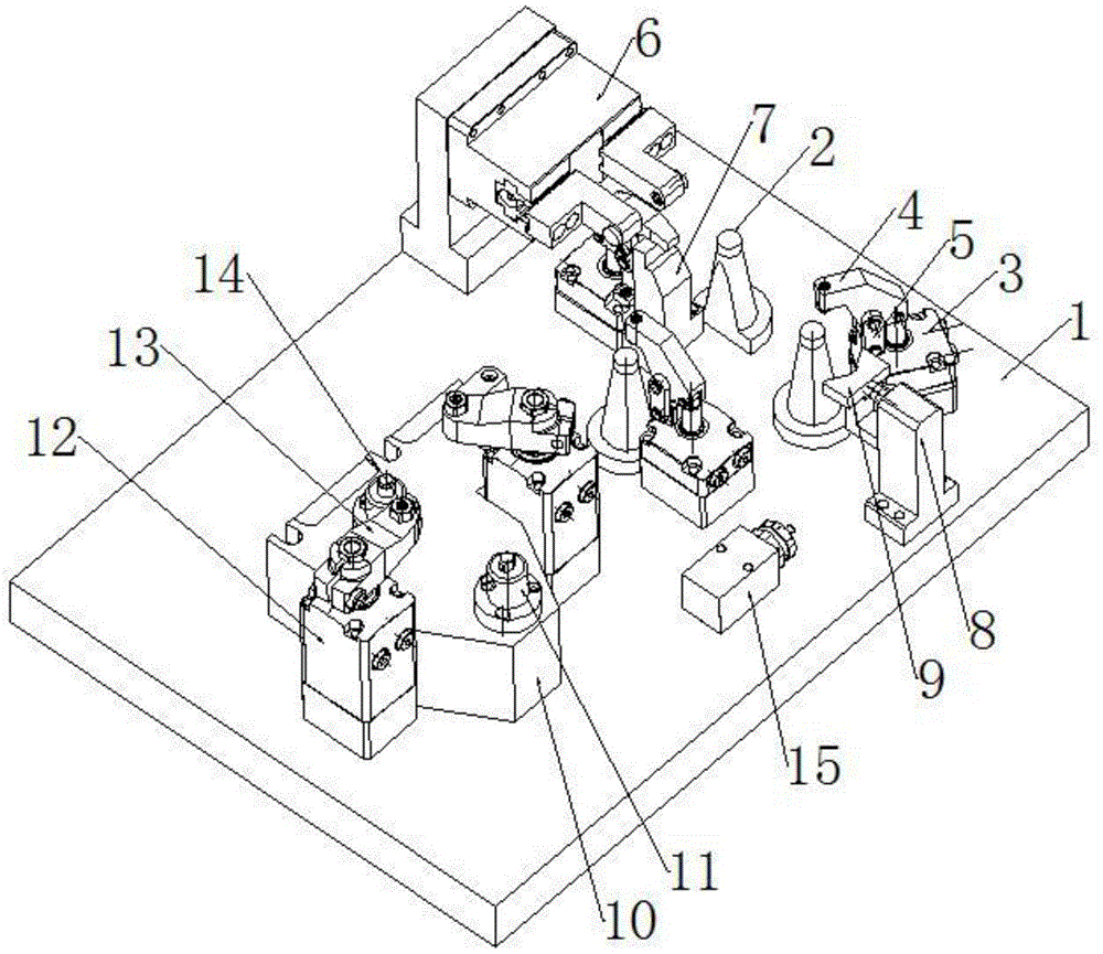
图1是本实用新型的结构示意图;Fig. 1 is the structural representation of the present utility model;
图2是本实用新型装夹机车构架端减震器座的结构示意图;Fig. 2 is the structural schematic diagram of the shock absorber seat at the frame end of the clamping locomotive of the present invention;
图中:1-底板,2-支撑柱,3-第一油缸,4-第一压臂,5-连接杆,6-对心台钳,7-竖直挡铁,8-第二油缸,9-V型夹块,10-支撑座,11-定位销,12-转角油缸,13-第二压臂,14-调节螺钉,15-顺序阀。In the picture: 1- base plate, 2- support column, 3- first oil cylinder, 4- first pressure arm, 5- connecting rod, 6- centering vise, 7- vertical block iron, 8- second oil cylinder, 9-V-type clamping block, 10-support seat, 11-positioning pin, 12-angle cylinder, 13-second pressure arm, 14-adjustment screw, 15-sequence valve.
具体实施方式Detailed ways
如图1所示,机车构架端减震器座加工夹具,包括底板1,在底板1一侧安装三个呈三角形布置且等高的支撑柱2,在三个支撑柱2左右两侧及后方分别竖直安装第一油缸3,每个第一油缸3的活塞杆顶端分别通过销轴铰接第一压臂4,每个第一压臂4的自由端指向三个支撑柱2侧,且在每个第一压臂4中部与底板1之间通过销轴连接连接杆5,在底板1上位于后部的第一油缸3后方安装对心台钳6,对心台钳6的二个卡爪朝前且左右相对运动,在底板1上位于后部的第一油缸3前方安装竖直挡铁7,在底板1上位于三个支撑柱2前方水平安装第二油缸8,第二油缸8的活塞杆指向竖直挡铁7,第二油缸8的活塞杆端女装V型夹块9;在底板1另一侧安装支撑座10,支撑座10顶部安装二个前后布置的定位销11,在底板1上位于支撑座10左右两侧分别竖直安装转角油缸12,每个转角油缸12的活塞杆顶端安装第二压臂13,在第二压臂13动作端通过螺纹竖直安装调节螺钉14,在底板1上安装与第一油缸3、第二油缸8和转角油缸12通过管路连接的顺序阀15。As shown in Figure 1, the locomotive frame end shock absorber seat processing fixture includes a base plate 1, and three triangularly arranged and equal
如图2所示,装夹机车构架端减震器座操作时,首先将底板1安装在数控机床操作平台,将顺序阀15的进油端通过管路连接油泵,然后将第一个机车构架端减震器座正向座在三个支撑柱2上,进行水平定位,启动对中台钳,对中台钳的二个卡爪顶靠在机车构架端减震器座左右两侧壁的内壁,进行左右定位,伸长第二油缸8的活塞杆,V型夹块9将机车构架端减震器座顶靠在竖直挡铁7,进行前后定位,最后伸长第一油缸3的活塞缸,第一压臂4的动作端下压,将机车构架端减震器座夹持固定在三个支撑柱2上。As shown in Figure 2, when clamping the shock absorber at the frame end of the locomotive, first install the base plate 1 on the operation platform of the CNC machine tool, connect the oil inlet end of the
再将第二个机车构架端减震器座倒置座在支撑座10上,进行水平面定位,同时使二个定位销11插入机车构架端减震器座的二个安装孔,进行前后左右定位,最后缩短转角油缸12的活塞杆,第二压臂13旋转并下压,将机车构架端减震器座夹持固定在支撑座10上,通过数控机床开始加工第一个机车构架端减震器座的正面和第二个机车构架端减震器座的背面。Then place the second shock absorber seat at the frame end of the locomotive upside down on the
以上仅为本实用新型的具体实施例而已,并不用于限制本实用新型,对于本领域的技术人员来说,本实用新型可以有各种更改和变化。凡在本实用新型的精神和原则之内,所作的任何修改、等同替换、改进等,均应包含在本实用新型的保护范围之内。The above are only specific embodiments of the present utility model, and are not intended to limit the present utility model. For those skilled in the art, the present utility model may have various modifications and changes. Any modification, equivalent replacement, improvement, etc. made within the spirit and principle of the present invention shall be included in the protection scope of the present invention.
Claims (3)
Priority Applications (1)
| Application Number | Priority Date | Filing Date | Title |
|---|---|---|---|
| CN201921479282.2U CN210756584U (en) | 2019-09-06 | 2019-09-06 | Locomotive frame end shock absorber seat adds clamping apparatus |
Applications Claiming Priority (1)
| Application Number | Priority Date | Filing Date | Title |
|---|---|---|---|
| CN201921479282.2U CN210756584U (en) | 2019-09-06 | 2019-09-06 | Locomotive frame end shock absorber seat adds clamping apparatus |
Publications (1)
| Publication Number | Publication Date |
|---|---|
| CN210756584U true CN210756584U (en) | 2020-06-16 |
Family
ID=71033914
Family Applications (1)
| Application Number | Title | Priority Date | Filing Date |
|---|---|---|---|
| CN201921479282.2U Active CN210756584U (en) | 2019-09-06 | 2019-09-06 | Locomotive frame end shock absorber seat adds clamping apparatus |
Country Status (1)
| Country | Link |
|---|---|
| CN (1) | CN210756584U (en) |
Cited By (1)
| Publication number | Priority date | Publication date | Assignee | Title |
|---|---|---|---|---|
| CN114850920A (en) * | 2022-06-06 | 2022-08-05 | 山东汇金股份有限公司 | Gap bridge type self-centering rotating hydraulic clamp suitable for multi-process machining |
-
2019
- 2019-09-06 CN CN201921479282.2U patent/CN210756584U/en active Active
Cited By (1)
| Publication number | Priority date | Publication date | Assignee | Title |
|---|---|---|---|---|
| CN114850920A (en) * | 2022-06-06 | 2022-08-05 | 山东汇金股份有限公司 | Gap bridge type self-centering rotating hydraulic clamp suitable for multi-process machining |
Similar Documents
| Publication | Publication Date | Title |
|---|---|---|
| CN204381908U (en) | A kind of exhaust manifold milling large fixture | |
| CN206083941U (en) | Drilling machine clamping apparatus | |
| CN209157752U (en) | A kind of torque tube tool for processing | |
| CN103639770A (en) | High-efficiency positioning fixture for cylinder borehole | |
| CN201309088Y (en) | Fixture of milling machine | |
| CN105855742B (en) | Intelligent welding equipment for automobile seat | |
| CN206185562U (en) | Car shell die casting mills location clamping jig | |
| CN117644412A (en) | Clamping and positioning tool for rear suspension bracket of automobile | |
| CN204366509U (en) | Double frock clamp is used in milling machine side milling processing | |
| CN103612142A (en) | Pneumatic clamp for automobile engine cam bearing cover | |
| CN218556367U (en) | Clamp for machining flange end of turbine shell | |
| CN216681209U (en) | 6D cylinder body anchor clamps | |
| CN207746771U (en) | Aluminum alloy die casting special fixture composite structure | |
| CN208051448U (en) | A kind of fixture for workpiece to be processed to be clamped | |
| CN205147894U (en) | Multistation hydraulically operated fixture | |
| CN202336686U (en) | Repair welding clamp | |
| CN205733994U (en) | A kind of fixture for milling machine | |
| CN106670535A (en) | Drill machine tool for four-cylinder exhaust pipe | |
| CN205325276U (en) | Compressor cylinder body four -axis rough machining positioning clamping device | |
| CN106584167B (en) | Flange Fork Parts Machining Jigs | |
| CN212145484U (en) | 4-shaft hydraulic clamp for shell | |
| CN210756590U (en) | Motor car combination seat adds clamping apparatus | |
| CN212918549U (en) | HS5 back sub vehicle frame saw cutting clamp | |
| CN209062639U (en) | A kind of fixture of simultaneous processing sewing machine plate tow sides | |
| CN210818586U (en) | Train centralized power rotary arm vertical machining fixture |
Legal Events
| Date | Code | Title | Description |
|---|---|---|---|
| GR01 | Patent grant | ||
| GR01 | Patent grant | ||
| PE01 | Entry into force of the registration of the contract for pledge of patent right | ||
| PE01 | Entry into force of the registration of the contract for pledge of patent right |
Denomination of utility model: Locomotive frame end shock absorber seat processing fixture Granted publication date: 20200616 Pledgee: Industrial Commercial Bank of China Ltd. Jinzhou branch Pledgor: JINZHOU JIETONG RAILWAY MACHINERY CO.,LTD. Registration number: Y2025980022677 |
|
| PC01 | Cancellation of the registration of the contract for pledge of patent right | ||
| PC01 | Cancellation of the registration of the contract for pledge of patent right |
Granted publication date: 20200616 Pledgee: Industrial Commercial Bank of China Ltd. Jinzhou branch Pledgor: JINZHOU JIETONG RAILWAY MACHINERY CO.,LTD. Registration number: Y2025980022677 |
|
| PE01 | Entry into force of the registration of the contract for pledge of patent right | ||
| PE01 | Entry into force of the registration of the contract for pledge of patent right |
Denomination of utility model: Locomotive frame end shock absorber seat processing fixture Granted publication date: 20200616 Pledgee: Industrial Commercial Bank of China Ltd. Jinzhou branch Pledgor: JINZHOU JIETONG RAILWAY MACHINERY CO.,LTD. Registration number: Y2026980016638 |