CN210752956U - Effectual milling machine of crocus - Google Patents
Effectual milling machine of crocus Download PDFInfo
- Publication number
- CN210752956U CN210752956U CN201921143054.8U CN201921143054U CN210752956U CN 210752956 U CN210752956 U CN 210752956U CN 201921143054 U CN201921143054 U CN 201921143054U CN 210752956 U CN210752956 U CN 210752956U
- Authority
- CN
- China
- Prior art keywords
- fixedly connected
- wall
- motor
- pipeline
- worm
- Prior art date
- Legal status (The legal status is an assumption and is not a legal conclusion. Google has not performed a legal analysis and makes no representation as to the accuracy of the status listed.)
- Active
Links
Images



Landscapes
- Crushing And Grinding (AREA)
Abstract
The utility model discloses an effectual milling machine of crocus, the on-line screen storage device comprises a base, the top fixedly connected with motor case of base, the left side fixedly connected with pipeline of motor case, the right side intercommunication of pipeline has a case, the bottom of top case and the top fixed connection of base, the left side of pipeline inner wall is seted up flutedly, and the inner wall sliding connection of recess has the cylinder, and the left side intercommunication of top case has the discharging pipe. The utility model discloses a set up the base, the motor case, the pipeline, the top case, the cylinder, the discharging pipe, including a motor, an end cap, a controller, and a cover plate, the pivot, the crushing leaf, the grinding apparatus, the ring gear, first belt pulley, the worm, the second belt pulley, the belt, the montant, the turbine, the disc, the movable rod, the frame, the pinion rack, inlet pipe and recess cooperate the use, the current poor and inhomogeneous problem of powder of milling machine crocus effect has been solved, this effectual milling machine of crocus, possess the effectual advantage of crocus, the practicality of milling machine has been improved, convenient to use person uses.
Description
Technical Field
The utility model relates to the technical field of machinery, specifically be an effectual milling machine of crocus.
Background
Food processing, which refers to grain grinding, feed processing, vegetable oil and sugar processing, slaughtering and meat processing, aquatic product processing and food processing activities of vegetables, fruits, nuts and the like which are directly carried out by taking agricultural, forestry, herding and fishery products as raw materials, is a type of generalized agricultural product processing industry, and food processing refers to the fact that edible things are changed better or more beneficial through certain procedures, and the raw grains or other raw materials are subjected to artificial treatment processes to form a novel directly edible product, and the process is food processing.
At food processing's in-process, need use the milling machine to carry out the crocus to food ingredients, but current milling machine crocus effect is poor and the powder is inhomogeneous, and later stage processing not convenient for influences food quality, has reduced the practicality of milling machine, and the person of not being convenient for uses.
SUMMERY OF THE UTILITY MODEL
An object of the utility model is to provide an effectual milling machine of crocus possesses the effectual advantage of crocus, has solved the poor and inhomogeneous problem of powder of current milling machine crocus effect.
In order to achieve the above object, the utility model provides a following technical scheme: a pulverizer with good pulverizing effect comprises a base, wherein a motor box is fixedly connected to the top of the base, a pipeline is fixedly connected to the left side of the motor box, a top box is communicated with the right side of the pipeline, the bottom of the top box is fixedly connected with the top of the base, a groove is formed in the left side of the inner wall of the pipeline, a roller is slidably connected to the inner wall of the groove, a discharging pipe is communicated with the left side of the top box, a motor is fixedly connected to the top of the right side of the inner wall of the motor box, a rotating shaft is fixedly connected to the output end of the motor, the left side of the rotating shaft penetrates into the discharging pipe and is fixedly connected with the inner wall of the discharging pipe through a first bearing, pulverizing leaves are fixedly connected to the top and the bottom of the rotating shaft, a grinding tool matched with the roller for use is fixedly connected to the left side of the surface of the, the right side of the inner wall of the motor box is fixedly connected with a worm through a second bearing, the surface of the worm is fixedly connected with a second belt pulley, the surface of the second belt pulley is in transmission connection with the surface of the first belt pulley through a belt, the left side of the worm penetrates into the top box and is fixedly connected with the inner wall of the top box through a third bearing, the bottom of the inner wall of the top box is fixedly connected with a vertical rod through a fourth bearing, the surface of the vertical rod is fixedly connected with a turbine, the back of the turbine is meshed with the front of the worm, the top of the vertical rod is fixedly connected with a disc, the left side of the top of the disc is fixedly connected with a movable rod, the surface of the movable rod is sleeved with a frame, the right side of the frame is connected with the inner wall of the top box in a sliding way, the top of the frame is fixedly connected with a toothed plate, the top of pinion rack and the bottom meshing of ring gear, the top intercommunication of pipeline has the inlet pipe.
Preferably, the right sides of the top and the bottom of the roller are fixedly connected with first sliding blocks, and the inner wall of the groove is provided with a first sliding chute matched with the first sliding blocks for use.
Preferably, the surface cover of worm is equipped with a support section of thick bamboo, the bottom fixedly connected with of a support section of thick bamboo props up the piece, the bottom of propping up the piece and the top fixed connection of base.
Preferably, the right side fixedly connected with second slider of frame, the inner wall of top case is seted up the second spout that uses with the cooperation of second slider.
Preferably, the left side fixedly connected with fifth bearing on cylinder surface, the left side of fifth bearing and the inner wall fixed connection of top case, the equal fixedly connected with a plurality of lug in the inner wall of cylinder and the surface of grinding apparatus, and a plurality of lug is the equidistance and distributes.
Preferably, the right side fixedly connected with backup pad of motor incasement wall, the top of backup pad and the bottom fixed connection of motor, the bottom fixedly connected with set-square of backup pad, the right side of set-square and the inner wall fixed connection of motor case, the model of motor is T80M 1-2.
Compared with the prior art, the beneficial effects of the utility model are as follows:
1. the utility model discloses a set up the base, the motor case, the pipeline, the top case, the cylinder, the discharging pipe, including a motor, an end cap, a controller, and a cover plate, the pivot, the crushing leaf, the grinding apparatus, the ring gear, first belt pulley, the worm, the second belt pulley, the belt, the montant, the turbine, the disc, the movable rod, the frame, the pinion rack, inlet pipe and recess cooperate the use, the current poor and inhomogeneous problem of powder of milling machine crocus effect has been solved, this effectual milling machine of crocus, possess the effectual advantage of crocus, the practicality of milling machine has been improved, convenient to use person uses.
2. The utility model discloses a cooperation of first slider and first spout is used, can reduce the friction of cylinder with the recess, the life of cylinder has been prolonged, spacing effect has been played to the cylinder simultaneously, setting through supporting a section of thick bamboo and a piece, the slope when can preventing the worm from rotating, the effect of support has been played to the worm simultaneously, cooperation through second slider and second spout is used, the friction of frame and overhead bin can be reduced, the life of frame has been prolonged, spacing effect has been played to the frame simultaneously, setting through the fifth bearing, can prevent the cylinder slope, the effect of support has been played to the cylinder simultaneously, setting through backup pad and set-square, can fix the motor, the effect of support has been played to the motor simultaneously.
Drawings
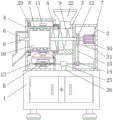
FIG. 1 is a schematic structural view of the present invention;
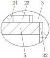
FIG. 2 is an enlarged view of the structure A in FIG. 1 according to the present invention;
FIG. 3 is an enlarged view of the structure B in FIG. 1 according to the present invention;
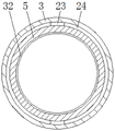
FIG. 4 is a left sectional view of the pipeline of FIG. 1 according to the present invention;
FIG. 5 is an enlarged top view of a portion of the structure of FIG. 1 according to the present invention;
fig. 6 is a left enlarged view of a partial structure of fig. 1 according to the present invention.
In the figure: the grinding machine comprises a base, a motor box 2, a pipeline 3, a top box 4, a roller 5, a discharge pipe 6, a motor 7, a rotating shaft 8, a grinding blade 9, a grinding tool 10, a toothed ring 11, a first belt pulley 12, a worm 13, a second belt pulley 14, a belt 15, a vertical rod 16, a turbine 17, a disc 18, a movable rod 19, a frame 20, a toothed plate 21, a feeding pipe 22, a first sliding block 23, a first sliding groove 24, a supporting cylinder 25, a supporting block 26, a second sliding block 27, a second sliding groove 28, a fifth bearing 29, a supporting plate 30, a triangular plate 31 and a groove 32.
Detailed Description
The technical solutions in the embodiments of the present invention will be described clearly and completely with reference to the accompanying drawings in the embodiments of the present invention, and it is obvious that the described embodiments are only some embodiments of the present invention, not all embodiments. Based on the embodiments in the present invention, all other embodiments obtained by a person skilled in the art without creative work belong to the protection scope of the present invention.
Referring to fig. 1-6, a pulverizer with good pulverizing effect comprises a base 1, a motor box 2 is fixedly connected to the top of the base 1, a pipeline 3 is fixedly connected to the left side of the motor box 2, a top box 4 is communicated with the right side of the pipeline 3, the bottom of the top box 4 is fixedly connected to the top of the base 1, a groove 32 is formed in the left side of the inner wall of the pipeline 3, a roller 5 is slidably connected to the inner wall of the groove 32, a first slider 23 is fixedly connected to the top and the right side of the bottom of the roller 5, a first chute 24 used in cooperation with the first slider 23 is formed in the inner wall of the groove 32, friction between the roller 5 and the groove 32 can be reduced by cooperation of the first slider 23 and the first chute 24, the service life of the roller 5 is prolonged, a limiting effect is achieved on the roller 5, a fifth bearing 29 is fixedly connected to the left side of the surface of the roller 5, the left side of the fifth bearing 29 is, the inner wall of the roller 5 and the surface of the grinding tool 10 are fixedly connected with a plurality of convex blocks which are distributed equidistantly, the roller 5 can be prevented from inclining by arranging a fifth bearing 29 and simultaneously plays a role of supporting the roller 5, the left side of the top box 4 is communicated with a discharge pipe 6, the top part of the right side of the inner wall of the motor box 2 is fixedly connected with a motor 7, the right side of the inner wall of the motor box 2 is fixedly connected with a supporting plate 30, the top part of the supporting plate 30 is fixedly connected with the bottom part of the motor 7, the bottom part of the supporting plate 30 is fixedly connected with a triangular plate 31, the right side of the triangular plate 31 is fixedly connected with the inner wall of the motor box 2, the model of the motor 7 is T80M1-2, the motor 7 can be fixed by arranging the supporting plate 30 and the triangular plate 31, the motor 7 is supported, the output end of the motor 7 is fixedly connected with a rotating shaft 8, the discharge pipe on the left side of the rotating shaft, the top and the bottom of the rotating shaft 8 are fixedly connected with crushing blades 9, the left side of the surface of the rotating shaft 8 is fixedly connected with a grinding tool 10 matched with the rotating cylinder 5 for use, the surface of the rotating cylinder 5 is fixedly connected with a toothed ring 11, the right side of the surface of the rotating shaft 8 is fixedly connected with a first belt pulley 12, the right side of the inner wall of the motor box 2 is fixedly connected with a worm 13 through a second bearing, the surface of the worm 13 is fixedly connected with a second belt pulley 14, the surface of the second belt pulley 14 is in transmission connection with the surface of the first belt pulley 12 through a belt 15, the left side of the worm 13 penetrates into the top box 4 and is fixedly connected with the inner wall of the top box 4 through a third bearing, the surface of the worm 13 is sleeved with a supporting cylinder 25, the bottom of the supporting cylinder 25 is fixedly connected with a supporting block 26, the bottom of the supporting block 26 is fixedly connected with the top of, meanwhile, the worm 13 is supported, the bottom of the inner wall of the top box 4 is fixedly connected with a vertical rod 16 through a fourth bearing, the surface of the vertical rod 16 is fixedly connected with a turbine 17, the back of the turbine 17 is meshed with the front of the worm 13, the top of the vertical rod 16 is fixedly connected with a disc 18, the left side of the top of the disc 18 is fixedly connected with a movable rod 19, the surface of the movable rod 19 is sleeved with a frame 20, the right side of the frame 20 is slidably connected with the inner wall of the top box 4, the right side of the frame 20 is fixedly connected with a second sliding block 27, the inner wall of the top box 4 is provided with a second sliding groove 28 matched with the second sliding block 27 for use, through the matched use of the second sliding block 27 and the second sliding groove 28, the friction between the frame 20 and the top box 4 can be reduced, the service life of the frame 20 is prolonged, meanwhile, the limiting effect is achieved on the frame 20, the top of the frame 20 is, the top of the pipeline 3 is communicated with a feeding pipe 22.
During the use, the user pours the raw materials into inside pipeline 3 by inlet pipe 22, output through motor 7 drives pivot 8, it is rotatory to smash leaf 9 and grinding apparatus 10, stirring leaf 9 is rotatory smashes the inside raw materials of pipeline 3, it is inside that the raw materials gets into cylinder 5 after smashing, grinding apparatus 10 is rotatory to grind the inside raw materials of cylinder 5, simultaneously, the rotatory first belt pulley 12 that drives of pivot 8, belt 15, second belt pulley 14, worm 13, turbine 17, montant 16, disc 18 and movable rod 19 are rotatory, movable rod 19 is rotatory drives frame 20 and grinding apparatus 21 back-and-forth movement, toothed plate 21 back-and-forth movement drives toothed ring 11 and cylinder 5 rotation, cylinder 5 is rotatory can cooperate grinding apparatus 10 to the raw materials this moment.
In summary, the following steps: this effectual milling machine of crocus, through setting up base 1, motor case 2, pipeline 3, top case 4, cylinder 5, discharging pipe 6, motor 7, pivot 8, crushing leaf 9, grinding apparatus 10, ring gear 11, first belt pulley 12, worm 13, second belt pulley 14, belt 15, montant 16, turbine 17, disc 18, movable rod 19, frame 20, pinion rack 21, the cooperation of inlet pipe 22 and recess 32 is used, the poor and inhomogeneous problem of powder of current milling machine crocus effect has been solved.
It is noted that, herein, relational terms such as first and second, and the like may be used solely to distinguish one entity or action from another entity or action without necessarily requiring or implying any actual such relationship or order between such entities or actions. Also, the terms "comprises," "comprising," or any other variation thereof, are intended to cover a non-exclusive inclusion, such that a process, method, article, or apparatus that comprises a list of elements does not include only those elements but may include other elements not expressly listed or inherent to such process, method, article, or apparatus.
Although embodiments of the present invention have been shown and described, it will be appreciated by those skilled in the art that changes, modifications, substitutions and alterations can be made in these embodiments without departing from the principles and spirit of the invention, the scope of which is defined in the appended claims and their equivalents.
Claims (6)
1. The utility model provides an effectual milling machine of crocus, includes base (1), its characterized in that: the top of the base (1) is fixedly connected with a motor box (2), the left side of the motor box (2) is fixedly connected with a pipeline (3), the right side of the pipeline (3) is communicated with a top box (4), the bottom of the top box (4) is fixedly connected with the top of the base (1), the left side of the inner wall of the pipeline (3) is provided with a groove (32), the inner wall of the groove (32) is slidably connected with a roller (5), the left side of the top box (4) is communicated with a discharging pipe (6), the top of the right side of the inner wall of the motor box (2) is fixedly connected with a motor (7), the output end of the motor (7) is fixedly connected with a rotating shaft (8), the left side of the rotating shaft (8) penetrates through the inside of the discharging pipe (6) and is fixedly connected with the inner wall of the discharging pipe (6) through a first bearing, and the top and the bottom, the grinding tool (10) is fixedly connected to the left side of the surface of the rotating shaft (8) and matched with the roller (5) for use, the surface of the roller (5) is fixedly connected with a toothed ring (11), the right side of the surface of the rotating shaft (8) is fixedly connected with a first belt pulley (12), the right side of the inner wall of the motor box (2) is fixedly connected with a worm (13) through a second bearing, the surface of the worm (13) is fixedly connected with a second belt pulley (14), the surface of the second belt pulley (14) is in transmission connection with the surface of the first belt pulley (12) through a belt (15), the left side of the worm (13) penetrates through the inside of the top box (4) and is fixedly connected with the inner wall of the top box (4) through a third bearing, the bottom of the inner wall of the top box (4) is fixedly connected with a vertical rod (16) through a fourth bearing, the surface of the, the back of turbine (17) and the positive meshing of worm (13), top fixedly connected with disc (18) of montant (16), the left side fixedly connected with movable rod (19) at disc (18) top, the surface cover of movable rod (19) is equipped with frame (20), the right side of frame (20) and the inner wall sliding connection of top case (4), the top fixedly connected with pinion rack (21) of frame (20), the top of pinion rack (21) and the bottom meshing of ring gear (11), the top intercommunication of pipeline (3) has inlet pipe (22).
2. An efficient grinding mill according to claim 1, characterized in that: the right side of cylinder (5) top and bottom all fixedly connected with first slider (23), first spout (24) of using with first slider (23) cooperation are seted up to the inner wall of recess (32).
3. An efficient grinding mill according to claim 1, characterized in that: the surface cover of worm (13) is equipped with a support section of thick bamboo (25), the bottom fixedly connected with of a support section of thick bamboo (25) props up piece (26), the bottom of propping up piece (26) and the top fixed connection of base (1).
4. An efficient grinding mill according to claim 1, characterized in that: the right side fixedly connected with second slider (27) of frame (20), second spout (28) that use with second slider (27) cooperation are seted up to the inner wall of top case (4).
5. An efficient grinding mill according to claim 1, characterized in that: the grinding wheel is characterized in that a fifth bearing (29) is fixedly connected to the left side of the surface of the roller (5), the left side of the fifth bearing (29) is fixedly connected with the inner wall of the top box (4), a plurality of convex blocks are fixedly connected to the inner wall of the roller (5) and the surface of the grinding tool (10), and the convex blocks are distributed equidistantly.
6. An efficient grinding mill according to claim 1, characterized in that: the right side fixedly connected with backup pad (30) of motor case (2) inner wall, the top of backup pad (30) and the bottom fixed connection of motor (7), the bottom fixedly connected with set-square (31) of backup pad (30), the right side of set-square (31) and the inner wall fixed connection of motor case (2), the model of motor (7) is T80M 1-2.
Priority Applications (1)
| Application Number | Priority Date | Filing Date | Title |
|---|---|---|---|
| CN201921143054.8U CN210752956U (en) | 2019-07-20 | 2019-07-20 | Effectual milling machine of crocus |
Applications Claiming Priority (1)
| Application Number | Priority Date | Filing Date | Title |
|---|---|---|---|
| CN201921143054.8U CN210752956U (en) | 2019-07-20 | 2019-07-20 | Effectual milling machine of crocus |
Publications (1)
| Publication Number | Publication Date |
|---|---|
| CN210752956U true CN210752956U (en) | 2020-06-16 |
Family
ID=71035131
Family Applications (1)
| Application Number | Title | Priority Date | Filing Date |
|---|---|---|---|
| CN201921143054.8U Active CN210752956U (en) | 2019-07-20 | 2019-07-20 | Effectual milling machine of crocus |
Country Status (1)
| Country | Link |
|---|---|
| CN (1) | CN210752956U (en) |
-
2019
- 2019-07-20 CN CN201921143054.8U patent/CN210752956U/en active Active
Similar Documents
| Publication | Publication Date | Title |
|---|---|---|
| CN209093502U (en) | One kind using sesame grinding device based on black sesame powder processing | |
| CN220443915U (en) | Crushing device | |
| CN212184252U (en) | Agricultural production processing is with crops straw rubbing crusher | |
| CN215917656U (en) | Pig feed production processing rubbing crusher | |
| CN110201740A (en) | A kind of cereal is peeled off and rolling device | |
| CN109092479A (en) | A kind of food processing milling device for being milled high-efficient | |
| CN212468273U (en) | Food processing is with smashing filter equipment | |
| CN113349236A (en) | Ball food forming processing equipment | |
| CN210332793U (en) | Agricultural by-product processing milling device | |
| CN211412149U (en) | Grinder is used in animal food processing | |
| CN217856377U (en) | Wheat grinder that flour processing used | |
| CN110721774A (en) | Grinder for food processing | |
| CN207252259U (en) | A kind of seed of maize harvesting machine breaks a device | |
| CN211359130U (en) | Grinding device for food processing | |
| CN112473805A (en) | Food processing is with equipment of breaing up | |
| CN215996966U (en) | Multistage reducing mechanism is used in production of chicken powder for fodder | |
| CN212975320U (en) | Reducing mechanism of animal health care medicine | |
| CN211190345U (en) | Reducing mechanism for food processing | |
| CN212882837U (en) | Raw materials milling equipment is used in food seasoning production | |
| CN211026574U (en) | Crushing apparatus for food processing | |
| CN213966974U (en) | High-efficient food processing raw materials rubbing crusher | |
| CN213825238U (en) | Food processing is with smashing machine that grinds | |
| CN209849033U (en) | Coconut shell crusher | |
| CN221452773U (en) | Food processing wheat grinder | |
| CN216396602U (en) | Environment-friendly and energy-saving grinding device for food processing |
Legal Events
| Date | Code | Title | Description |
|---|---|---|---|
| GR01 | Patent grant | ||
| GR01 | Patent grant |