CN210740622U - A kind of ventilation equipment with good dust removal and cleaning effect - Google Patents
A kind of ventilation equipment with good dust removal and cleaning effect Download PDFInfo
- Publication number
- CN210740622U CN210740622U CN201921160382.9U CN201921160382U CN210740622U CN 210740622 U CN210740622 U CN 210740622U CN 201921160382 U CN201921160382 U CN 201921160382U CN 210740622 U CN210740622 U CN 210740622U
- Authority
- CN
- China
- Prior art keywords
- fixedly connected
- air
- air inlet
- inlet pipe
- filter
- Prior art date
- Legal status (The legal status is an assumption and is not a legal conclusion. Google has not performed a legal analysis and makes no representation as to the accuracy of the status listed.)
- Expired - Fee Related
Links
Images


Landscapes
- Structures Of Non-Positive Displacement Pumps (AREA)
Abstract
本实用新型公开了一种除尘清洁效果好的通风设备,包括蜗形壳、底板和内齿圈,所述底板的顶部与蜗形壳的底部固定连接,底板的顶部且位于蜗形壳出风口的一端固定连接有出风管,蜗形壳进风口的一端固定连接有进风管,进风管内壁的左侧固定连接有过滤板,本实用新型涉及通风设备技术领域。该除尘清洁效果好的通风设备,能够防止空气中的灰尘进入壳体内部,喷头喷水与清理刷相互配合,能够对过滤板进行清理,可以防止过滤板堵塞,能够有效防止灰尘附着在壳体内壁或叶轮表面,提高了该通风设备的出身效果,实用性更高,导流块与导流叶随转动杆转动,能够加快空气的流动速度,有效提升该装置的通风效果,提高了工作效率。
The utility model discloses a ventilation device with good dust removal and cleaning effect, comprising a volute casing, a bottom plate and an inner gear ring. The top of the bottom plate is fixedly connected with the bottom of the volute casing, and the top of the bottom plate is located at the air outlet of the volute casing. One end of the air inlet pipe is fixedly connected with an air outlet pipe, one end of the air inlet of the volute casing is fixedly connected with an air inlet pipe, and the left side of the inner wall of the air inlet pipe is fixedly connected with a filter plate. The utility model relates to the technical field of ventilation equipment. The ventilation equipment with good dust removal and cleaning effect can prevent dust in the air from entering the interior of the casing. The nozzle water spray and the cleaning brush cooperate with each other to clean the filter plate, prevent the filter plate from clogging, and effectively prevent dust from adhering to the casing. The surface of the wall or the impeller improves the origin effect of the ventilation equipment, and the practicability is higher. The guide block and the guide vane rotate with the rotating rod, which can speed up the flow speed of the air, effectively improve the ventilation effect of the device, and improve the work efficiency. .
Description
技术领域technical field
本实用新型涉及通风设备技术领域,具体为一种除尘清洁效果好的通风设备。The utility model relates to the technical field of ventilation equipment, in particular to a ventilation equipment with good dust removal and cleaning effect.
背景技术Background technique
通风设备使用广泛,现有的通风设备如通风机是依靠输入的机械能,提高气体压力并排送气体的机械,它是一种从动的流体机械,排气压力低于1.5×10^4帕,现代通风机广泛用于工厂、矿井、隧道、冷却塔、车辆、船舶和建筑物的通风、排尘和冷却,锅炉和工业炉窑的通风和引风,空气调节设备和家用电器设备中的冷却和通风,谷物的烘干和选送,风洞风源和气垫船的充气和推进等。Ventilation equipment is widely used. Existing ventilation equipment such as ventilator is a machine that relies on input mechanical energy to increase gas pressure and discharge gas. It is a driven fluid machine, and the exhaust pressure is lower than 1.5 × 10^4 Pa. Modern ventilators are widely used for ventilation, dust removal and cooling in factories, mines, tunnels, cooling towers, vehicles, ships and buildings, ventilation and induced draft in boilers and industrial furnaces, cooling in air conditioning equipment and household appliances and ventilation, drying and selection of grains, wind source of wind tunnel and inflation and propulsion of hovercraft, etc.
现有的通风设备如通风机所处的工作环境一般灰尘较多,长时间使用后通风机内壁及叶轮的表面等位置会附着大量的灰尘,影响通风设备的正常工作,而现有的通风设备无法防止灰尘进入其内部,直接影响通风设备的除尘效果,且现有的通风设备只靠一处叶轮转动提供风力,工作效率较低,同方效果较差,降低了实用性。Existing ventilation equipment, such as the working environment where the ventilator is located, generally has a lot of dust. After long-term use, a large amount of dust will adhere to the inner wall of the fan and the surface of the impeller, which affects the normal operation of the ventilation equipment. It is impossible to prevent dust from entering its interior, which directly affects the dust removal effect of the ventilation equipment, and the existing ventilation equipment only relies on the rotation of one impeller to provide wind power, so the work efficiency is low, the effect of the same method is poor, and the practicability is reduced.
实用新型内容Utility model content
针对现有技术的不足,本实用新型提供了一种除尘清洁效果好的通风设备,解决了通风设备内部容易附着或堆积灰尘,影响设备正常工作,初沉效果较差,及工作效率较低,降低实用性的问题。In view of the deficiencies of the prior art, the utility model provides a ventilation device with good dust removal and cleaning effect, which solves the problem that dust is easily attached or accumulated inside the ventilation device, which affects the normal operation of the device, the primary sedimentation effect is poor, and the work efficiency is low. Reduced usability issues.
为实现以上目的,本实用新型通过以下技术方案予以实现:一种除尘清洁效果好的通风设备,包括蜗形壳、底板和内齿圈,所述底板的顶部与蜗形壳的底部固定连接,所述底板的顶部且位于蜗形壳出风口的一端固定连接有出风管,所述蜗形壳进风口的一端固定连接有进风管,所述进风管内壁的左侧固定连接有过滤板,并且过滤板左侧的中心转动连接有连接杆,所述连接杆的左端固定连接有与内齿圈相啮合的齿轮,并且内齿圈表面的顶部与底部均固定连接有清理刷,所述进风管的内壁且位于过滤板的左侧固定连接有环形滑板,所述清理刷的顶部与底部均开设有与环形滑板相适配的滑槽,所述进风管内壁的底部开设有导流槽。In order to achieve the above purpose, the utility model is realized by the following technical solutions: a ventilation device with good dust removal and cleaning effect, comprising a volute casing, a bottom plate and an inner gear ring, and the top of the bottom plate is fixedly connected with the bottom of the volute casing, The top of the bottom plate and one end of the air outlet of the volute casing is fixedly connected with an air outlet pipe, one end of the air inlet of the volute casing is fixedly connected with an air inlet pipe, and the left side of the inner wall of the air inlet pipe is fixedly connected with a filter. The center of the left side of the filter plate is rotatably connected with a connecting rod, the left end of the connecting rod is fixedly connected with a gear engaged with the inner gear ring, and the top and bottom of the surface of the inner gear ring are fixedly connected with a cleaning brush, so An annular slide plate is fixedly connected to the inner wall of the air inlet duct and is located on the left side of the filter plate, the top and bottom of the cleaning brush are provided with a chute that fits with the annular slide plate, and the bottom of the inner wall of the air inlet duct is provided with Diversion groove.
优选的,所述进风管的顶部连通有导管,所述导管的底端贯穿进风管并延伸至进风管的内部,所述导管的底端固定连接有喷头。Preferably, a conduit is communicated with the top of the air inlet pipe, the bottom end of the conduit penetrates the air inlet pipe and extends to the interior of the air inlet pipe, and a spray head is fixedly connected to the bottom end of the conduit.
优选的,所述连接杆的右端贯穿过滤板并延伸至过滤板的右侧,所述连接杆位于过滤板右侧的一端固定连接有导流块。Preferably, the right end of the connecting rod penetrates the filter plate and extends to the right side of the filter plate, and an end of the connecting rod located on the right side of the filter plate is fixedly connected with a flow guide block.
优选的,所述底板顶部的右侧固定连接有支撑杆,所述支撑杆的顶端固定连接有支撑板,并且支撑板的左侧与蜗形壳的右侧固定连接。Preferably, a support rod is fixedly connected to the right side of the top of the bottom plate, a support plate is fixedly connected to the top end of the support rod, and the left side of the support plate is fixedly connected to the right side of the volute casing.
优选的,所述支撑板的顶部固定连接有电机,并且电机输出轴的一端固定连接有转动杆,所述转动杆远离电机的一端贯穿蜗形壳和进风管并延伸至进风管的内部,所述转动杆的表面且位于蜗形壳的内部固定连接有叶轮。Preferably, a motor is fixedly connected to the top of the support plate, and a rotating rod is fixedly connected to one end of the output shaft of the motor. , the surface of the rotating rod and the interior of the volute casing are fixedly connected with the impeller.
优选的,所述转动杆位于进风管内部的一端与导流块的右侧固定连接,所述导流块的表面固定连接有导流叶。Preferably, one end of the rotating rod located inside the air inlet pipe is fixedly connected to the right side of the guide block, and a guide vane is fixedly connected to the surface of the guide block.
有益效果beneficial effect
本实用新型提供了一种除尘清洁效果好的通风设备。与现有技术相比具备以下有益效果:The utility model provides a ventilation device with good dust removal and cleaning effect. Compared with the prior art, it has the following beneficial effects:
(1)、该除尘清洁效果好的通风设备,通过进风管内壁的左侧固定连接有过滤板,连接杆的左端固定连接有与内齿圈相啮合的齿轮,内齿圈表面的顶部与底部均固定连接有清理刷,进风管内壁的底部开设有导流槽,进风管的顶部连通有导管,导管的底端固定连接有喷头,过滤板能够防止该通风装置工作时,空气中的灰尘进入壳体内部,且喷头喷水与清理刷相互配合,能够对过滤板进行清理,可以防止过滤板堵塞,能够有效防止灰尘附着在壳体内壁或叶轮表面,提高了该通风设备的出身效果,实用性更高。(1) The ventilation equipment with good dust removal and cleaning effect is fixedly connected with a filter plate through the left side of the inner wall of the air inlet pipe, and the left end of the connecting rod is fixedly connected with a gear that meshes with the inner gear ring. The bottoms are fixedly connected with cleaning brushes, the bottom of the inner wall of the air inlet pipe is provided with a diversion groove, the top of the air inlet pipe is connected with a duct, and the bottom end of the duct is fixedly connected with a nozzle, and the filter plate can prevent the ventilation device from working. The dust enters the inside of the casing, and the water spray of the nozzle and the cleaning brush cooperate with each other, which can clean the filter plate, prevent the filter plate from clogging, and effectively prevent the dust from adhering to the inner wall of the casing or the surface of the impeller, which improves the origin of the ventilation equipment. more effective and more practical.
(2)、该除尘清洁效果好的通风设备,通过连接杆的右端贯穿过滤板并延伸至过滤板的右侧,连接杆位于过滤板右侧的一端固定连接有导流块,转动杆位于进风管内部的一端与导流块的右侧固定连接,导流块的表面固定连接有导流叶,导流块与导流叶随转动杆转动,能够加快空气的流动速度,有效提升该装置的通风效果,提高了工作效率。(2) The ventilation equipment with good dust removal and cleaning effect penetrates through the filter plate and extends to the right side of the filter plate through the right end of the connecting rod. The end of the connecting rod located on the right side of the filter plate is fixedly connected with a diversion block, and the rotating rod is located in the inlet. One end of the inside of the air duct is fixedly connected to the right side of the guide block. The surface of the guide block is fixedly connected with a guide vane. The guide block and the guide vane rotate with the rotating rod, which can speed up the flow of air and effectively improve the device. The ventilation effect improves the work efficiency.
附图说明Description of drawings
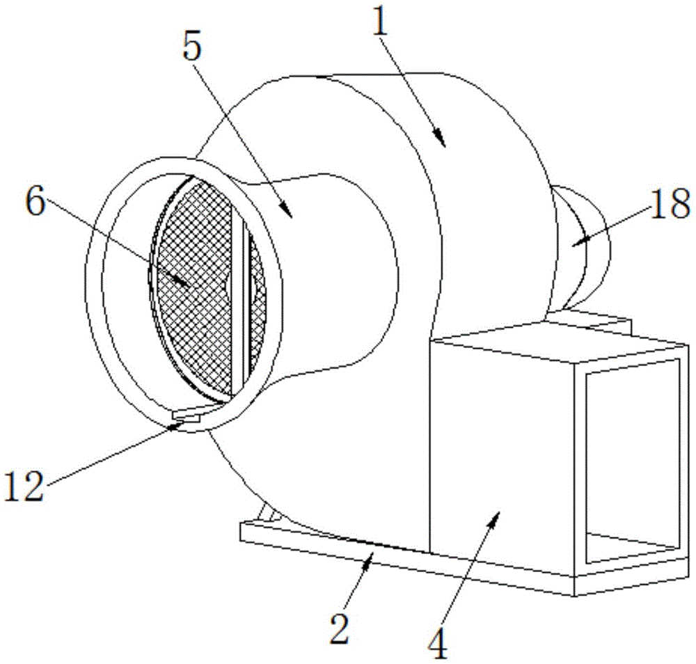
图1为本实用新型结构的立体图;Fig. 1 is the perspective view of the utility model structure;
图2为本实用新型结构的剖视图;Fig. 2 is the sectional view of the utility model structure;
图3为本实用新型图2中A处的局部放大图;Fig. 3 is a partial enlarged view of the place A in Fig. 2 of the utility model;
图4为本实用新型图2中B处的局部放大图;Fig. 4 is a partial enlarged view of the place B in Fig. 2 of the utility model;
图5为本实用新型内齿圈和过滤板结构的左视图。Figure 5 is a left side view of the structure of the inner gear ring and filter plate of the present invention.
图中:1蜗形壳、2底板、3内齿圈、4出风管、5进风管、6过滤板、7连接杆、8齿轮、9清理刷、10环形滑板、11滑槽、12导流槽、13导管、14喷头、15导流块、16支撑杆、17支撑板、18电机、19转动杆、20叶轮、21导流叶。In the picture: 1 volute shell, 2 bottom plate, 3 inner gear ring, 4 air outlet pipe, 5 air inlet pipe, 6 filter plate, 7 connecting rod, 8 gear, 9 cleaning brush, 10 annular slide plate, 11 chute, 12 Guide groove, 13 conduit, 14 nozzle, 15 guide block, 16 support rod, 17 support plate, 18 motor, 19 rotating rod, 20 impeller, 21 guide vane.
具体实施方式Detailed ways
下面将结合本实用新型实施例中的附图,对本实用新型实施例中的技术方案进行清楚、完整地描述,显然,所描述的实施例仅仅是本实用新型一部分实施例,而不是全部的实施例。基于本实用新型中的实施例,本领域普通技术人员在没有做出创造性劳动前提下所获得的所有其他实施例,都属于本实用新型保护的范围。The technical solutions in the embodiments of the present utility model will be clearly and completely described below with reference to the accompanying drawings in the embodiments of the present utility model. Obviously, the described embodiments are only a part of the embodiments of the present utility model, rather than all the implementations. example. Based on the embodiments of the present invention, all other embodiments obtained by those of ordinary skill in the art without creative work fall within the protection scope of the present invention.
请参阅图1-5,本实用新型提供一种技术方案:一种除尘清洁效果好的通风设备,包括蜗形壳1、底板2和内齿圈3,底板2顶部的右侧固定连接有支撑杆16,支撑杆16的顶端固定连接有支撑板17,支撑板17的顶部固定连接有电机18,电机18通过导线与控制系统及外部电源连接,并且电机18输出轴的一端固定连接有转动杆19,转动杆19位于进风管5内部的一端与导流块15的右侧固定连接,导流块15的表面固定连接有导流叶21,导流块15与导流叶21相互配合能够提高空气的流动速度,降低过滤板6对空气流速的影响,转动杆19远离电机18的一端贯穿蜗形壳1和进风管5并延伸至进风管5的内部,转动杆19的表面且位于蜗形壳1的内部固定连接有叶轮20,并且支撑板17的左侧与蜗形壳1的右侧固定连接,底板2的顶部与蜗形壳1的底部固定连接,底板2的顶部且位于蜗形壳1出风口的一端固定连接有出风管4,蜗形壳1进风口的一端固定连接有进风管5,进风管5的顶部连通有导管13,导管13与外部水泵相连通,导管13的底端贯穿进风管5并延伸至进风管5的内部,导管13的底端固定连接有喷头14,进风管5内壁的左侧固定连接有过滤板6,并且过滤板6左侧的中心转动连接有连接杆7,连接杆7的右端贯穿过滤板6并延伸至过滤板6的右侧,连接杆7位于过滤板6右侧的一端固定连接有导流块15,连接杆7的左端固定连接有与内齿圈3相啮合的齿轮8,并且内齿圈3表面的顶部与底部均固定连接有清理刷9,进风管5的内壁且位于过滤板6的左侧固定连接有环形滑板10,清理刷9的顶部与底部均开设有与环形滑板10相适配的滑槽11,进风管5内壁的底部开设有导流槽12,导流槽12能够将清理过滤板6流下的污水导出进风管5。1-5, the present utility model provides a technical solution: a ventilation device with good dust removal and cleaning effect, comprising a volute casing 1, a
使用时,通过外部开关控制电机18工作,使转动杆19带动叶轮20和导流块15转动,空气从进风管5流入蜗形壳1内部,然后通过出风管4排出蜗形壳1,完成通风流程,此过程中,导流块15转动会带动连接杆7转动,通过齿轮8和内齿圈3相互配合带动清理刷9沿着环形滑轨10转动,清理刷9能够清理过滤板6上附着的灰尘,通过外部水泵,使水流流经导管13,并从喷头14喷出,使水流喷洒在过滤板6上,与清理刷9相互配合对过滤板6进行清理,防止灰尘进入该通风装置内部,清理过滤板6的污水可以通过导流槽12排出进风管5。When in use, the
需要说明的是,在本文中,诸如第一和第二等之类的关系术语仅仅用来将一个实体或者操作与另一个实体或操作区分开来,而不一定要求或者暗示这些实体或操作之间存在任何这种实际的关系或者顺序。而且,术语“包括”、“包含”或者其任何其他变体意在涵盖非排他性的包含,从而使得包括一系列要素的过程、方法、物品或者设备不仅包括那些要素,而且还包括没有明确列出的其他要素,或者是还包括为这种过程、方法、物品或者设备所固有的要素。It should be noted that, in this document, relational terms such as first and second are only used to distinguish one entity or operation from another entity or operation, and do not necessarily require or imply any relationship between these entities or operations. any such actual relationship or sequence exists. Moreover, the terms "comprising", "comprising" or any other variation thereof are intended to encompass a non-exclusive inclusion such that a process, method, article or device that includes a list of elements includes not only those elements, but also includes not explicitly listed or other elements inherent to such a process, method, article or apparatus.
尽管已经示出和描述了本实用新型的实施例,对于本领域的普通技术人员而言,可以理解在不脱离本实用新型的原理和精神的情况下可以对这些实施例进行多种变化、修改、替换和变型,本实用新型的范围由所附权利要求及其等同物限定。Although the embodiments of the present invention have been shown and described, it will be understood by those skilled in the art that various changes and modifications can be made to these embodiments without departing from the principles and spirit of the present invention , alternatives and modifications, the scope of the present invention is defined by the appended claims and their equivalents.
Claims (6)
Priority Applications (1)
| Application Number | Priority Date | Filing Date | Title |
|---|---|---|---|
| CN201921160382.9U CN210740622U (en) | 2019-07-23 | 2019-07-23 | A kind of ventilation equipment with good dust removal and cleaning effect |
Applications Claiming Priority (1)
| Application Number | Priority Date | Filing Date | Title |
|---|---|---|---|
| CN201921160382.9U CN210740622U (en) | 2019-07-23 | 2019-07-23 | A kind of ventilation equipment with good dust removal and cleaning effect |
Publications (1)
| Publication Number | Publication Date |
|---|---|
| CN210740622U true CN210740622U (en) | 2020-06-12 |
Family
ID=71008257
Family Applications (1)
| Application Number | Title | Priority Date | Filing Date |
|---|---|---|---|
| CN201921160382.9U Expired - Fee Related CN210740622U (en) | 2019-07-23 | 2019-07-23 | A kind of ventilation equipment with good dust removal and cleaning effect |
Country Status (1)
| Country | Link |
|---|---|
| CN (1) | CN210740622U (en) |
Cited By (9)
| Publication number | Priority date | Publication date | Assignee | Title |
|---|---|---|---|---|
| CN113390173A (en) * | 2021-06-02 | 2021-09-14 | 丽水大广通环保科技工程有限公司 | Ventilating duct capable of preventing particles from entering interior and precipitating and accumulating |
| CN113404715A (en) * | 2021-08-17 | 2021-09-17 | 南通市吉腾鼓风机有限公司 | Air blower for air conditioning |
| CN113606705A (en) * | 2021-09-29 | 2021-11-05 | 南通西南机械制造有限公司 | Remove haze formula new fan |
| CN113638916A (en) * | 2021-10-13 | 2021-11-12 | 南通西南机械制造有限公司 | Water atomization humidification centrifugal fan |
| CN113970145A (en) * | 2021-11-08 | 2022-01-25 | 重庆黄牛通风设备有限公司 | But ventilation equipment of self-cleaning filter screen |
| CN114955614A (en) * | 2022-06-19 | 2022-08-30 | 湖北铂仁机电设备有限公司 | A industrial dust collector for feed bin top |
| CN114963375A (en) * | 2022-04-28 | 2022-08-30 | 广东德成实验室科技有限公司 | Circulating ventilation system for laboratory |
| CN116123796A (en) * | 2022-11-30 | 2023-05-16 | 江苏拓博制冷科技有限公司 | Full-automatic industrial refrigeration equipment convenient to clean |
| CN118676083A (en) * | 2024-08-26 | 2024-09-20 | 成都兴仁科技有限公司 | Packaging piece based on SiP packaging radio frequency receiver |
-
2019
- 2019-07-23 CN CN201921160382.9U patent/CN210740622U/en not_active Expired - Fee Related
Cited By (12)
| Publication number | Priority date | Publication date | Assignee | Title |
|---|---|---|---|---|
| CN113390173A (en) * | 2021-06-02 | 2021-09-14 | 丽水大广通环保科技工程有限公司 | Ventilating duct capable of preventing particles from entering interior and precipitating and accumulating |
| CN113404715A (en) * | 2021-08-17 | 2021-09-17 | 南通市吉腾鼓风机有限公司 | Air blower for air conditioning |
| CN113606705A (en) * | 2021-09-29 | 2021-11-05 | 南通西南机械制造有限公司 | Remove haze formula new fan |
| CN113606705B (en) * | 2021-09-29 | 2021-12-14 | 南通西南机械制造有限公司 | Remove haze formula new fan |
| CN113638916A (en) * | 2021-10-13 | 2021-11-12 | 南通西南机械制造有限公司 | Water atomization humidification centrifugal fan |
| CN113970145A (en) * | 2021-11-08 | 2022-01-25 | 重庆黄牛通风设备有限公司 | But ventilation equipment of self-cleaning filter screen |
| CN114963375A (en) * | 2022-04-28 | 2022-08-30 | 广东德成实验室科技有限公司 | Circulating ventilation system for laboratory |
| CN114955614A (en) * | 2022-06-19 | 2022-08-30 | 湖北铂仁机电设备有限公司 | A industrial dust collector for feed bin top |
| CN114955614B (en) * | 2022-06-19 | 2023-03-10 | 湖北铂仁机电设备有限公司 | A industrial dust collector for feed bin top |
| CN116123796A (en) * | 2022-11-30 | 2023-05-16 | 江苏拓博制冷科技有限公司 | Full-automatic industrial refrigeration equipment convenient to clean |
| CN116123796B (en) * | 2022-11-30 | 2024-04-16 | 山东欧菲特能源科技有限公司 | Full-automatic industrial refrigeration equipment convenient to clean |
| CN118676083A (en) * | 2024-08-26 | 2024-09-20 | 成都兴仁科技有限公司 | Packaging piece based on SiP packaging radio frequency receiver |
Similar Documents
| Publication | Publication Date | Title |
|---|---|---|
| CN212250631U (en) | A fully automatic cleaning function fan | |
| CN205164365U (en) | Automatic cleaning device of cleaning tube inner wall | |
| CN104471319B (en) | Pm2.5 ventilation fan | |
| CN116696807A (en) | Novel automatic clean industrial fan | |
| CN220929709U (en) | Fan capable of automatically cleaning filter screen | |
| CN111412574A (en) | An intelligent fresh air system | |
| CN104654456B (en) | It is a kind of to remove haze air-conditioning with cleaning function | |
| CN209761867U (en) | A special dust filter blower for urban underground comprehensive pipe gallery | |
| CN210740624U (en) | A kind of ventilation equipment with self-cleaning function | |
| CN216343073U (en) | Centrifugal force supply structure of centrifugal fire-fighting smoke exhaust fan | |
| CN214146050U (en) | Draught fan of environmental protection dust fall | |
| CN208289697U (en) | Mobile Sanding Room dust pelletizing system and mobile Sanding Room | |
| CN206770251U (en) | A range fume blower with automatic cleaning function | |
| CN207714240U (en) | A kind of civil engineering works Special dedusting device | |
| CN216342869U (en) | Composite body for sealing fan | |
| CN211936104U (en) | A dust removal device for HVAC engineering construction | |
| CN213574730U (en) | High-efficiency air supply device for blast furnace steam-driven fan | |
| CN213598266U (en) | Low-noise self-dedusting ventilator | |
| CN108499267A (en) | A kind of sack cleaner with deashing function | |
| CN209083610U (en) | A kind of abutment wall blower | |
| CN221647203U (en) | A high efficiency centrifugal fan | |
| CN104006430A (en) | Novel bladeless oil smoke exhausting device | |
| CN206113071U (en) | High-efficiency pressurized exhaust duct | |
| CN108126437B (en) | Shutter type water film dust remover | |
| CN216440202U (en) | A kind of air supply system of self-cleaning air supply unit |
Legal Events
| Date | Code | Title | Description |
|---|---|---|---|
| GR01 | Patent grant | ||
| GR01 | Patent grant | ||
| CP01 | Change in the name or title of a patent holder | ||
| CP01 | Change in the name or title of a patent holder |
Address after: 315000 No. 58, Qingshui puyuji Road, Jiaochuan street, Zhenhai District, Ningbo City, Zhejiang Province Patentee after: Yishimer fan (Ningbo) Co.,Ltd. Address before: 315000 No. 58, Qingshui puyuji Road, Jiaochuan street, Zhenhai District, Ningbo City, Zhejiang Province Patentee before: Ningbo Chengfeng energy saving equipment Co.,Ltd. |
|
| CF01 | Termination of patent right due to non-payment of annual fee | ||
| CF01 | Termination of patent right due to non-payment of annual fee |
Granted publication date: 20200612 |