CN210737504U - Counter-force device for static sounding in deep soft soil - Google Patents
Counter-force device for static sounding in deep soft soil Download PDFInfo
- Publication number
- CN210737504U CN210737504U CN201921588170.0U CN201921588170U CN210737504U CN 210737504 U CN210737504 U CN 210737504U CN 201921588170 U CN201921588170 U CN 201921588170U CN 210737504 U CN210737504 U CN 210737504U
- Authority
- CN
- China
- Prior art keywords
- gear
- weight
- static sounding
- threaded rod
- frame
- Prior art date
- Legal status (The legal status is an assumption and is not a legal conclusion. Google has not performed a legal analysis and makes no representation as to the accuracy of the status listed.)
- Expired - Fee Related
Links
- 230000003068 static effect Effects 0.000 title claims abstract description 30
- 239000002689 soil Substances 0.000 title claims abstract description 21
- XEEYBQQBJWHFJM-UHFFFAOYSA-N Iron Chemical compound [Fe] XEEYBQQBJWHFJM-UHFFFAOYSA-N 0.000 claims description 13
- 238000005553 drilling Methods 0.000 claims description 9
- 229910052742 iron Inorganic materials 0.000 claims description 6
- 230000000149 penetrating effect Effects 0.000 claims description 5
- 241001074085 Scophthalmus aquosus Species 0.000 abstract 1
- 230000001360 synchronised effect Effects 0.000 description 3
- 230000007547 defect Effects 0.000 description 2
- 230000000694 effects Effects 0.000 description 2
- 230000004075 alteration Effects 0.000 description 1
- 230000009286 beneficial effect Effects 0.000 description 1
- 238000006243 chemical reaction Methods 0.000 description 1
- 238000001125 extrusion Methods 0.000 description 1
- 210000001503 joint Anatomy 0.000 description 1
- 238000012986 modification Methods 0.000 description 1
- 230000004048 modification Effects 0.000 description 1
- 230000035515 penetration Effects 0.000 description 1
- 239000000523 sample Substances 0.000 description 1
- 238000006467 substitution reaction Methods 0.000 description 1
Images


Landscapes
- Investigation Of Foundation Soil And Reinforcement Of Foundation Soil By Compacting Or Drainage (AREA)
Abstract
The utility model discloses a counter-force device of static sounding in dark weak soil, including weight, frame landing leg and brill income end, the frame landing leg is installed to the lower extreme of weight, and the lower terminal surface of weight has seted up the spacing groove to the connecting axle is installed to the inboard of spacing groove, the stopper is installed in the outside of connecting axle, and the outside of stopper and frame landing leg is connected, the support frame is installed to the upper end bolt of weight, and the internal surface middle-end of weight runs through installs movable handle to the first gear of surface fixed connection of movable handle. This counterforce device of static sounding in dark weak soil, along with the lower terminal surface and the frame landing leg block of nose bar, it will extrude inboard stopper, and then makes the stopper take place the skew upwards to rotate to carry out spacing support through its terminal surface to the outside of frame landing leg, further increase the frame landing leg support stability of integrated device to static sounding appearance.
Description
Technical Field
The utility model relates to a static sounding technical field specifically is a counter-force device of static sounding in dark weak soil.
Background
Static sounding is with the static pressure with conical probe according to the even speed of certain speed in the soil, measure its penetration resistance, and divide the soil layer according to the size of its resistance that receives, thereby confirm the engineering nature of soil, and need use counterforce device when detecting, it adopts three kinds of forms to solve usually, utilize the earth anchor promptly, heavy object or car dead weight are as the counter-force, wherein, the device that utilizes the earth anchor to do the counter-force is good because of economic nature and convenience, application scope is wider, but there is certain defect in the counterforce device of current static sounding in deep weak soil still, just for example:
1. the static sounding counterforce device with the reducing spiral line ground anchor and the stress application disc, disclosed as CN204959749U, is simple in structure, portable, practical, labor-saving and reliable, and is suitable for popularization and use of static sounding tests with the reducing spiral line ground anchor and the stress application disc, but in the scheme, a user needs to respectively adjust and fix the positions of a plurality of drilling head ground anchors, so that inconvenience is brought to the operation of the user;
2. the existing counter-force device for static sounding in deep soft soil cannot stably limit and fix the stand supporting leg of the static sounding instrument, so that the stability of the counter-force device has certain defects.
In order to solve the above problems, innovative design based on the structure of the original reaction device is urgently needed.
SUMMERY OF THE UTILITY MODEL
An object of the utility model is to provide a counter-force device of static sounding in dark weak soil to the needs that provide in solving above-mentioned background art carry out position control to a plurality of first earth anchors of creeping into respectively and fix, can't stabilize the problem of carrying on spacing fixed to the frame landing leg of static sounding appearance.
In order to achieve the above object, the utility model provides a following technical scheme: a counter-force device for static sounding in deep soft soil comprises a weight, a rack supporting leg and a drilling end, wherein the rack supporting leg is installed at the lower end of the weight, a limiting groove is formed in the lower end face of the weight, a connecting shaft is installed on the inner side of the limiting groove, a limiting block is installed on the outer side of the connecting shaft and connected with the outer side of the rack supporting leg, a supporting frame is installed on an upper end bolt of the weight, a movable handle penetrates through the middle end of the inner surface of the weight, a first gear is fixedly connected to the outer surface of the movable handle, a second gear penetrates through the inner surfaces of the supporting frame and the end portion of the weight, a lug is fixedly connected to the outer side of the second gear and connected with the inner surface of the weight, the outer surface of the lower end of the second gear is connected with a first chain, and a second chain is installed on the outer surface of, and the second gear is connected with the inner surface of the support frame, a cavity is arranged in the second gear, a threaded rod is arranged at the middle end of the second gear in a penetrating mode and connected with the weights and the inner surface of the support frame, and a drilling end is fixedly connected to the lower end of the threaded rod.
Preferably, the limiting block is of a triangular structure, the limiting block forms a rotating structure through a pressing iron, and the outer side of the limiting block is connected with the outer surface of the support leg of the rack in a clamping mode.
Preferably, the second gear is in an H-shaped structure, the inner part of the upper end of the second gear is in threaded connection with the threaded rod, and the second gear and the inner surface of the weight form a rotating structure through the convex block.
Preferably, the number of the second chains is 2 about the center point of the first chain, the second chains are vertically distributed with the first chain, and the second chains and the inner surface of the weight form a rotating structure through a second gear.
Preferably, the threaded rod is symmetrically provided with 4 about the central point of the weight, the drilling end at the lower end of the threaded rod is of a spiral structure, and the threaded rod is connected with the inner part of the lower end of the second gear in a nested manner through a cavity.
Compared with the prior art, the beneficial effects of the utility model are that: the counter-force device is used for static sounding in deep soft soil;
1. the movable triangular limiting blocks are arranged, the lower end faces of the weights continuously move downwards to be in contact with the outer sides of the stand supporting legs, the stand supporting legs clamped with the movable triangular limiting blocks extrude the limiting blocks on the inner sides of the stand supporting legs, and the limiting blocks are enabled to deflect and rotate upwards, so that the outer sides of the stand supporting legs are limited and supported through the end faces of the limiting blocks, and the supporting stability of the integral device on the stand supporting legs of the static sounding instrument is further improved;
2. be provided with synchronous pivoted heliciform and bore the end, the user only needs handheld activity handle to drive first gear and meshes the rotation, can drive 2 second gear synchronous rotations through first chain, the second chain that the second gear will pass through the upper end at this moment meshes the rotation in step, and then let and wherein 4 threaded rods of end threaded connection drive the heliciform and bore the end and rotate downwards in step, and then let the stable downstream of weight carry on spacing fixedly to the support of frame landing leg of static sounding appearance, let user's operation simple and convenient high-efficient more.
Drawings
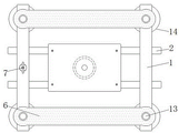
Fig. 1 is a schematic top view of the present invention;
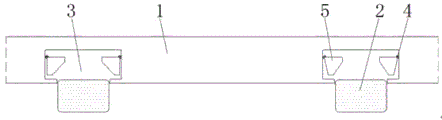
FIG. 2 is a schematic front view of the present invention;
fig. 3 is a schematic cross-sectional structural view of the threaded rod of the present invention;
fig. 4 is a schematic top view of the first chain of the present invention;
fig. 5 is a schematic cross-sectional structural view of a second gear of the present invention;
fig. 6 is a schematic cross-sectional structural view of the weight of the present invention.
In the figure: 1. pressing iron; 2. a frame leg; 3. a limiting groove; 4. a connecting shaft; 5. a limiting block; 6. a support frame; 7. a movable handle; 8. a first gear; 9. a first chain; 10. a second gear; 11. a bump; 12. a second chain; 13. a threaded rod; 14. drilling in the end; 15. a cavity.
Detailed Description
The technical solutions in the embodiments of the present invention will be described clearly and completely with reference to the accompanying drawings in the embodiments of the present invention, and it is obvious that the described embodiments are only some embodiments of the present invention, not all embodiments. Based on the embodiments in the present invention, all other embodiments obtained by a person skilled in the art without creative work belong to the protection scope of the present invention.
Referring to fig. 1-6, the present invention provides a technical solution: a counter-force device for static sounding in deep soft soil comprises a weight 1, a frame leg 2, a limiting groove 3, a connecting shaft 4, a limiting block 5, a support frame 6, a movable handle 7, a first gear 8, a first chain 9, a second gear 10, a lug 11, a second chain 12, a threaded rod 13, a drilling end 14 and a cavity 15, wherein the frame leg 2 is installed at the lower end of the weight 1, the limiting groove 3 is formed in the lower end face of the weight 1, the connecting shaft 4 is installed on the inner side of the limiting groove 3, the limiting block 5 is installed on the outer side of the connecting shaft 4, the limiting block 5 is connected with the outer side of the frame leg 2, the limiting block 5 is in a triangular structure, the limiting block 5 forms a rotating structure through the weight 1, the outer side of the limiting block 5 is in clamping connection with the outer surface of the frame leg 2, when the lower end face of the weight 1 contacts with the outer side of the frame leg 2, the limiting block 5 on the inner side can be extruded, thereby supporting the frame legs 2;
a support frame 6 is installed on an upper end bolt of the weight 1, a movable handle 7 is installed at the middle end of the inner surface of the weight 1 in a penetrating mode, a first gear 8 is fixedly connected to the outer surface of the movable handle 7, a second gear 10 is installed on the inner surfaces of the end portions of the support frame 6 and the weight 1 in a penetrating mode, a protruding block 11 is fixedly connected to the outer side of the second gear 10, the protruding block 11 is connected with the inner surface of the weight 1, the second gear 10 is in an H-shaped structure, the inner portion of the upper end of the second gear 10 is in threaded connection with a threaded rod 13, the second gear 10 and the inner surface of the weight 1 form a rotating structure through the protruding block 11, and the first gear 8 drives 2 second gears 10 through a first chain 9 and can drive 4 meshed threaded rods 13 to synchronously perform position adjusting rotation;
the outer surface of the lower end of the second gear 10 is connected with the first chain 9, the outer surface of the upper end of the second gear 10 is provided with a second chain 12, the second gear 10 is connected with the inner surface of the support frame 6, 2 second chains 12 are symmetrically arranged about the central point of the first chain 9, the second chains 12 and the first chain 9 are vertically distributed, the second chains 12 and the inner surface of the weight 1 form a rotating structure through the second gear 10, and the horizontally placed first chain 9 can drive 2 second chains 12 which are vertically distributed to synchronously transmit while rotating through the second gear 10;
the inside of second gear 10 is provided with cavity 15, and the middle-end of second gear 10 runs through and installs threaded rod 13, and threaded rod 13 is connected with the internal surface of weight 1 and support frame 6, the lower extreme fixedly connected with of threaded rod 13 bores end 14, threaded rod 13 is provided with 4 about the central point symmetry of weight 1, and the end 14 that bores of threaded rod 13 lower extreme is the heliciform structure, and threaded rod 13 passes through cavity 15 and the inside nested connection that is of lower extreme of second gear 10, let and stabilize pivoted threaded rod 13 through second gear 10, can drive the heliciform that the lower extreme is fixed and bore end 14 synchronous and ground contact.
The working principle is as follows: when the counter-force device for static sounding in deep soft soil is used, according to the figures 1-4, the counter-force device is firstly placed at a position to be operated, then a static sounding instrument and a press iron 1 are placed according to the position of a test point, then the drilling end 14 at the lower end of a threaded rod 13 is pressed into the soft soil ground, then a user can hold a movable handle 7 at the outer side of the press iron 1 by hand to drive a first gear 8 along the interior of the press iron, at the moment, the first gear 8 drives a first chain 9 which is meshed with the first chain to synchronously transmit, according to the figures 3-5, at the moment, 2H-shaped second gears 10 at the end part of the first chain 9 rotate along with the movable handle, and then 2 second chains 12 which are meshed with the lower end surface are driven along the inner surface of a support frame 6, and 4 threaded rods 13 at the end are in threaded connection drive a spiral drilling end 14 to synchronously drill downwards at the same time when the 4 second gears 10 synchronously rotate in the same direction, so that the whole device stably moves downwards to the outer side of the stand leg 2;
according to 1 and fig. 6, along with the activity that constantly moves down through the drilling-in end 14 of the lower terminal surface of weight 1, it will contact the 2 outsides of frame landing leg of static sounding appearance, and frame landing leg 2 will be along with stable butt joint carries out the block to 3 insides of spacing groove, and the frame landing leg 2 of accomodating will carry out extrusion contact to the 5 outer ends of stopper of 3 inboards of spacing groove, and then make stopper 5 take place the skew and upwards rotate through connecting axle 4, thereby will block to carry out spacing support to the outside of frame landing leg 2 through its pivoted lower terminal surface, and then cooperate 4 threaded rods 13 and the fixed further increase of drilling-in end 14 the overall device to the support stability of static sounding appearance frame landing leg 2, whole practicality has been increased.
Those not described in detail in this specification are within the skill of the art.
Although embodiments of the present invention have been shown and described, it will be appreciated by those skilled in the art that changes, modifications, substitutions and alterations can be made in these embodiments without departing from the principles and spirit of the invention, the scope of which is defined in the appended claims and their equivalents.
Claims (5)
1. The utility model provides a counter-force device of static sounding in dark soft soil, includes nose bar (1), frame landing leg (2) and bores into end (14), its characterized in that: the lower end of the weight (1) is provided with a rack supporting leg (2), the lower end face of the weight (1) is provided with a limiting groove (3), the inner side of the limiting groove (3) is provided with a connecting shaft (4), the outer side of the connecting shaft (4) is provided with a limiting block (5), the limiting block (5) is connected with the outer side of the rack supporting leg (2), the upper end of the weight (1) is provided with a supporting frame (6) through a bolt, the middle end of the inner surface of the weight (1) is provided with a movable handle (7) in a penetrating way, the outer surface of the movable handle (7) is fixedly connected with a first gear (8), the inner surfaces of the supporting frame (6) and the end part of the weight (1) are provided with a second gear (10) in a penetrating way, the outer side of the second gear (10) is fixedly connected with a lug (11), the lug (11) is connected with the inner surface of the weight (1), the outer surface of the lower, and the upper end surface mounting of second gear (10) has second chain (12) to second gear (10) is connected with the internal surface of support frame (6), the inside of second gear (10) is provided with cavity (15), and the middle-end of second gear (10) runs through and installs threaded rod (13), and threaded rod (13) are connected with the internal surface of weight (1) and support frame (6), the lower extreme fixedly connected with of threaded rod (13) bores end (14).
2. A counterforce device of static sounding in deep soft soils according to claim 1, characterized in that: stopper (5) are triangle-shaped structure, and stopper (5) constitute rotating-structure through nose bar (1) to the outside of stopper (5) is connected for the block with the surface of frame landing leg (2).
3. A counterforce device of static sounding in deep soft soils according to claim 1, characterized in that: the second gear (10) is in an H-shaped structure, the inner part of the upper end of the second gear (10) is in threaded connection with the threaded rod (13), and the second gear (10) and the inner surface of the weight (1) form a rotating structure through the convex block (11).
4. A counterforce device of static sounding in deep soft soils according to claim 1, characterized in that: the number of the second chains (12) is 2 about the center point of the first chain (9), the second chains (12) and the first chain (9) are vertically distributed, and the second chains (12) and the inner surface of the press iron (1) form a rotating structure through a second gear (10).
5. A counterforce device of static sounding in deep soft soils according to claim 1, characterized in that: the threaded rod (13) is symmetrically provided with 4 about the central point of the weight (1), the drilling end (14) at the lower end of the threaded rod (13) is of a spiral structure, and the threaded rod (13) is connected with the lower end of the second gear (10) in a nested mode through the cavity (15).
Priority Applications (1)
| Application Number | Priority Date | Filing Date | Title |
|---|---|---|---|
| CN201921588170.0U CN210737504U (en) | 2019-09-24 | 2019-09-24 | Counter-force device for static sounding in deep soft soil |
Applications Claiming Priority (1)
| Application Number | Priority Date | Filing Date | Title |
|---|---|---|---|
| CN201921588170.0U CN210737504U (en) | 2019-09-24 | 2019-09-24 | Counter-force device for static sounding in deep soft soil |
Publications (1)
| Publication Number | Publication Date |
|---|---|
| CN210737504U true CN210737504U (en) | 2020-06-12 |
Family
ID=70987743
Family Applications (1)
| Application Number | Title | Priority Date | Filing Date |
|---|---|---|---|
| CN201921588170.0U Expired - Fee Related CN210737504U (en) | 2019-09-24 | 2019-09-24 | Counter-force device for static sounding in deep soft soil |
Country Status (1)
| Country | Link |
|---|---|
| CN (1) | CN210737504U (en) |
-
2019
- 2019-09-24 CN CN201921588170.0U patent/CN210737504U/en not_active Expired - Fee Related
Similar Documents
| Publication | Publication Date | Title |
|---|---|---|
| CN209911369U (en) | Soil pollution real-time detection device | |
| CN213543554U (en) | Depth detection device for water conservancy and hydropower | |
| CN219416020U (en) | Bridge engineering bored pile hole bottom sediment layer thickness measuring device | |
| CN214537708U (en) | Manual hole digging foundation pile diameter measuring device | |
| CN218766364U (en) | Dykes and dams intensity detection device for hydraulic engineering detects | |
| CN209878682U (en) | Data acquisition unit with ultrasonic probe | |
| CN213335929U (en) | Measuring device for central deviation of H-shaped steel and I-shaped steel | |
| CN205857150U (en) | A kind of building lot drill rod detector | |
| CN201637632U (en) | Needling structure test device of hydraulic bracket | |
| CN218034765U (en) | Foundation construction sediment thickness detection device | |
| CN209082467U (en) | A kind of novel heavy duty dynamic penetrometer | |
| CN208980248U (en) | A kind of guide tracked jacking system | |
| CN208183642U (en) | Self-lifting type marine drilling platform two-driven-by-one lifting unit prototype installation | |
| CN215985555U (en) | Building material's detection device | |
| CN214219608U (en) | Foundation planning equipment for building planning engineering | |
| CN214537691U (en) | Coal mine tunnel bulging amount measuring device | |
| CN211717730U (en) | Waterproof cloth waterproof performance detection device | |
| CN204040588U (en) | A kind of anti-offset assembly of power transmission tower frame | |
| CN210562099U (en) | Foundation detection device | |
| CN212058738U (en) | Level detection device for building engineering | |
| CN212159669U (en) | Ultrasonic detection device for building steel structure | |
| CN220490437U (en) | Drill core sampling equipment for farmland soil detection | |
| CN112577834A (en) | Multifunctional bending-resistant and shearing-resistant device for prestressed concrete pipe pile | |
| CN108825206B (en) | Wellhead cable direction changing device for gas storage well detection and detection method | |
| CN212963543U (en) | Special water level detection device of hydraulic engineering design |
Legal Events
| Date | Code | Title | Description |
|---|---|---|---|
| GR01 | Patent grant | ||
| GR01 | Patent grant | ||
| CF01 | Termination of patent right due to non-payment of annual fee |
Granted publication date: 20200612 Termination date: 20210924 |
|
| CF01 | Termination of patent right due to non-payment of annual fee |