CN210735400U - Conveyer belt cleaning device - Google Patents
Conveyer belt cleaning device Download PDFInfo
- Publication number
- CN210735400U CN210735400U CN201921134047.1U CN201921134047U CN210735400U CN 210735400 U CN210735400 U CN 210735400U CN 201921134047 U CN201921134047 U CN 201921134047U CN 210735400 U CN210735400 U CN 210735400U
- Authority
- CN
- China
- Prior art keywords
- conveyer belt
- supporting
- base
- cleaning device
- fixedly mounted
- Prior art date
- Legal status (The legal status is an assumption and is not a legal conclusion. Google has not performed a legal analysis and makes no representation as to the accuracy of the status listed.)
- Expired - Fee Related
Links
Images



Landscapes
- Cleaning In General (AREA)
Abstract
The utility model belongs to the technical field of the conveyer belt cleaning device technique and specifically relates to a conveyer belt cleaning device, the on-line screen storage device comprises a base, the equal fixed mounting in four corners department of base bottom has supporting mechanism, one side fixed mounting at base top has first support frame, rotate through first coupling mechanism on the inner wall of first support frame and be connected with the follower roller. The utility model discloses the conveyer belt body is the transmission all the time under drive arrangement's effect, through water pump intercommunication running water, lead to water pipe pump sending to shower nozzle, wash the both sides of conveyer belt bottom respectively simultaneously, then start the cylinder and promote brush head and conveyer belt body and contact each other, reach and brush the washing to the conveyer belt body that washes, this realization of conveyer belt that brushes obtains the second through another shower nozzle and washes, thereby reach and carry out abluent purpose to the residue on the conveyer belt body, avoid the residue to cause too much to the conveyer belt wearing and tearing, reduce the book of conveyer belt and decrease speed.
Description
Technical Field
The utility model relates to a conveyer belt cleaning device technical field especially relates to a conveyer belt cleaning device.
Background
The conveyer belt, also called conveyer belt, is a composite product of rubber, fiber and metal, or a composite product of plastic and fabric, which is used in the conveyer belt to carry and convey materials. The conveyer belt is widely applied to occasions with short conveying distance and small conveying amount in the industries of cement, coking, metallurgy, chemical industry, steel and the like.
The conveyer belt can remain the residue that transported object left in transportation process surface, can cause the pollution to the surface of conveyer belt is worn and torn to the surface of conveyer belt to the residue of accumulation, accelerates the breakage of conveyer belt.
SUMMERY OF THE UTILITY MODEL
The utility model aims at solving the residual that has the conveyer belt among the prior art and can remain the transportation article and leave on the surface in transportation process, can cause the pollution to the surface of conveyer belt to the accumulated residual can cause wearing and tearing to the surface of conveyer belt, the shortcoming of losing of conveyer belt with higher speed, and a conveyer belt cleaning device who proposes.
In order to achieve the above purpose, the utility model adopts the technical scheme that: a conveying belt cleaning device comprises a base, wherein supporting mechanisms are fixedly mounted at four corners of the bottom of the base, a first supporting frame is fixedly mounted at one side of the top of the base, a follower roller is rotatably connected onto the inner wall of the first supporting frame through a first connecting mechanism, a second supporting frame is fixedly mounted at the other side of the top of the base, a driving roller is rotatably connected onto the inner wall of the second supporting frame through a second connecting mechanism, the driving roller is driven by a driving device on the front side of the second supporting frame, the driving roller and the follower roller are in transmission connection through a conveying belt body, a cleaning pool is fixedly mounted at the middle position of the top of the base, an air cylinder is fixedly mounted at the top of the base and below the cleaning pool, an output rod of the air cylinder penetrates into the cleaning pool and is fixedly provided with a brush head, and the top of the brush head is in, the positive fixed mounting of base has the water pump, the drainage end at the water pump back has two water pipes through the shunt tubes reposition of redundant personnel, the water pipe penetrates the inside and the fixed intercommunication of wasing the pond and has the shower nozzle, the inner wall fixed connection in shower nozzle and washing pond, two the shower nozzle distributes in the both sides of brush head, the both sides at the washing pond back are all fixed the intercommunication and have the delivery pipe, the rear of base is provided with the catchment car.
Preferably, the supporting mechanism comprises a supporting leg, the supporting leg is fixedly installed at the bottom of the base, and a mounting hole is formed in the top of the supporting leg.
Preferably, the first connecting mechanism comprises first supporting shafts, the two first supporting shafts are fixedly installed on the front side and the rear side of the follower roller, and the end parts of the first supporting shafts are rotatably connected with the inner wall of the first supporting frame through first bearings.
Preferably, the second connecting mechanism comprises a second supporting shaft, the second supporting shaft is fixedly mounted on the back of the driving roller, and the rear end of the second supporting shaft is rotatably connected with the inner wall of the second supporting frame through a second bearing.
Preferably, drive arrangement includes the motor, motor fixed mounting is in the front of second support frame, the output fixed mounting of motor has the pivot, the tip of pivot pass the second support frame and with the front fixed connection of drive roller.
Preferably, the bottom of washing pond inner wall corresponds the fixed position of cylinder output pole and installs the sealing washer, sealing washer sliding connection is on the surface of cylinder output pole.
Compared with the prior art, the utility model discloses following beneficial effect has:
1. the utility model discloses the conveyer belt body is the transmission all the time under drive arrangement's effect, through water pump intercommunication running water, lead to water pipe pump sending to shower nozzle, wash the both sides of conveyer belt bottom respectively simultaneously, then start the cylinder and promote brush head and conveyer belt body and contact each other, reach and brush the washing to the conveyer belt body that washes, this realization of conveyer belt that brushes obtains the second through another shower nozzle and washes, thereby reach and carry out abluent purpose to the residue on the conveyer belt body, avoid the residue to cause too much to the conveyer belt wearing and tearing, reduce the book of conveyer belt and decrease speed.
2. Through setting up the catchment car, played the effect of collecting the delivery pipe from wasing pond exhaust water to the reutilization of being convenient for.
Drawings
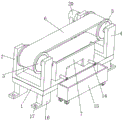
Fig. 1 is a first perspective view of a conveyor belt cleaning device of the present invention;
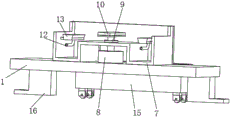
fig. 2 is a second perspective view of a conveyor belt cleaning device of the present invention;
fig. 3 is a schematic structural diagram of a top view of a conveyor belt cleaning device according to the present invention;
fig. 4 is a perspective view of the belt cleaning device of the present invention after the front surface of the splitting cleaning tank is opened;
fig. 5 is a perspective view of the belt cleaning device of the present invention after the belt and the section are removed.
In the figure: the cleaning device comprises a base 1, a first support frame 2, a follower roller 3, a second support frame 4, a driving roller 5, a conveying belt body 6, a cleaning pool 7, a cylinder 8, a sealing ring 9, a brush head 10, a water pump 11, a water pipe 12, a spray head 13, a discharge pipe 14, a water collecting vehicle 15, support legs 16, a mounting hole 17, a first support shaft 18, a first bearing 19, a motor 20, a rotating shaft 21, a second support shaft 22 and a second bearing 23.
Detailed Description
The following description is presented to disclose the invention so as to enable any person skilled in the art to practice the invention. The preferred embodiments in the following description are given by way of example only, and other obvious variations will occur to those skilled in the art.
As shown in figures 1-5, the conveyor belt cleaning device comprises a base 1, wherein supporting mechanisms are fixedly mounted at four corners of the bottom of the base 1 and comprise supporting legs 16, the supporting legs 16 are fixedly mounted at the bottom of the base 1, mounting holes 17 are formed in the tops of the supporting legs 16, and the supporting legs 16 provided with the mounting holes 17 are arranged to play a role in fixing the base 1 through conveniently inserting and connecting fixing piles.
One side fixed mounting at base 1 top has first support frame 2, it is connected with follower roller 3 to rotate through a coupling mechanism on the inner wall of first support frame 2, first coupling mechanism includes first supporting shaft 18, first supporting shaft 18 fixed mounting is both sides around follower roller 3, the tip of first supporting shaft 18 rotates through first bearing 19 and is connected with the inner wall of first support frame 2, through setting up first supporting shaft 18 and first bearing 19, played and rotated the effect of connecting on the inner wall of first support frame 2 with follower roller 3.
The opposite side fixed mounting at base 1 top has second support frame 4, rotate through second coupling mechanism on the inner wall of second support frame 4 and be connected with drive roller 5, second coupling mechanism includes second back shaft 22, second back shaft 22 fixed mounting is at the back of drive roller 5, the rear end of second back shaft 22 rotates through the inner wall of second bearing 23 with second support frame 4 to be connected, through setting up second back shaft 4 and second bearing 23, played and rotated drive roller 5 and connect the effect on the 4 inner walls of second support frame.
A cleaning pool 7 is fixedly arranged at the middle position of the top of a base 1, a cylinder 8 is fixedly arranged at the top of the base 1 and below the cleaning pool 7, an output rod of the cylinder 8 penetrates into the cleaning pool 7 and is fixedly provided with a brush head 10, a sealing ring 9 is fixedly arranged at the bottom of the inner wall of the cleaning pool 7 corresponding to the position of the output rod of the cylinder 8, the sealing ring 9 is connected on the surface of the output rod of the cylinder 8 in a sliding manner, the sealing ring 9 is arranged to seal a gap between the output rod of the cylinder 8 and the cleaning pool 7, the top of the brush head 10 is contacted with the bottom of a conveying belt body 6, a water pump 11 is fixedly arranged at the front of the base 1, a water discharging end at the back of the water pump 11 is divided into two water pipes 12 through a dividing pipe, the water pipes 12 penetrate into the cleaning pool 7 and are fixedly communicated with a spray head 13, the, conveyer belt body 6 is the transmission all the time under drive arrangement's effect, through 11 intercommunication running water of water pump, pass through 12 pump sending of water pipe to shower nozzle 13, wash simultaneously the both sides of conveyer belt body 6 bottom respectively, then start cylinder 8 and promote brush head 10 and conveyer belt body 6 and contact each other, reach and brush the washing to the conveyer belt body 6 that washes, the conveyer belt body 6 that brushes can obtain the second through another shower nozzle 13 and wash, thereby reach and carry out abluent mesh to the residue on the conveyer belt body 6, avoid the residue to lead to the fact conveyer belt wearing and tearing too much, reduce the book of conveyer belt and decrease speed.
Both sides at the back of washing pond 7 all are fixed the intercommunication and have delivery pipe 14, and the rear of base 1 is provided with catchment car 15, through setting up catchment car 15, has played the effect of collecting from wasing pond exhaust water to the delivery pipe to reuse in convenient for.
The foregoing shows and describes the general principles, essential features, and advantages of the invention. It will be understood by those skilled in the art that the present invention is not limited to the above embodiments, and that the principles of the present invention may be applied to any other embodiment without departing from the spirit and scope of the present invention. The scope of the invention is defined by the appended claims and equivalents thereof.
Claims (6)
1. A conveying belt cleaning device comprises a base (1) and is characterized in that supporting mechanisms are fixedly mounted at four corners of the bottom of the base (1), a first supporting frame (2) is fixedly mounted at one side of the top of the base (1), a follower roller (3) is rotatably connected onto the inner wall of the first supporting frame (2) through a first connecting mechanism, a second supporting frame (4) is fixedly mounted at the other side of the top of the base (1), a driving roller (5) is rotatably connected onto the inner wall of the second supporting frame (4) through a second connecting mechanism, the driving roller (5) is driven by a driving device on the front side of the second supporting frame (4), the driving roller (5) is in transmission connection with the follower roller (3) through a conveying belt body (6), a cleaning pool (7) is fixedly mounted at the middle position of the top of the base (1), and a cylinder (8) is fixedly mounted at the top of the base (1) and below the cleaning pool (7), the delivery lever of cylinder (8) penetrates and washs inside and fixed mounting in pond (7) and has brush head (10), the top of brush head (10) and the bottom of conveyer belt body (6) contact each other, the positive fixed mounting of base (1) has water pump (11), the drainage end at the water pump (11) back has two water pipes (12) through the shunt tubes reposition of redundant personnel, water pipe (12) penetrate the inside and fixed intercommunication of wasing pond (7) and have shower nozzle (13), shower nozzle (13) and the inner wall fixed connection who washs pond (7), two shower nozzle (13) distribute in the both sides of brush head (10), the both sides at the washing pond (7) back all are fixed the intercommunication and have delivery pipe (14), the rear of base (1) is provided with catchment car (15).
2. The cleaning device for the conveying belt according to claim 1, wherein the supporting mechanism comprises supporting legs (16), the supporting legs (16) are fixedly arranged at the bottom of the base (1), and mounting holes (17) are formed in the tops of the supporting legs (16).
3. A conveyor belt cleaning device as claimed in claim 1, characterized in that the first connecting means comprises first supporting shafts (18), two of the first supporting shafts (18) are fixedly arranged at the front and rear sides of the follower roller (3), and the end of the first supporting shaft (18) is rotatably connected with the inner wall of the first supporting frame (2) through a first bearing (19).
4. A conveyor belt cleaning device as claimed in claim 1, wherein the second connecting mechanism comprises a second supporting shaft (22), the second supporting shaft (22) is fixedly mounted on the back of the driving roller (5), and the rear end of the second supporting shaft (22) is rotatably connected with the inner wall of the second supporting frame (4) through a second bearing (23).
5. A conveyor belt cleaning device as claimed in claim 1, wherein the driving device comprises a motor (20), the motor (20) is fixedly mounted on the front surface of the second supporting frame (4), the output end of the motor (20) is fixedly mounted with a rotating shaft (21), and the end of the rotating shaft (21) passes through the second supporting frame (4) and is fixedly connected with the front surface of the driving roller (5).
6. A cleaning device for a conveying belt according to claim 1, wherein a sealing ring (9) is fixedly installed at the bottom of the inner wall of the cleaning tank (7) corresponding to the position of the output rod of the air cylinder (8), and the sealing ring (9) is slidably connected to the surface of the output rod of the air cylinder (8).
Priority Applications (1)
| Application Number | Priority Date | Filing Date | Title |
|---|---|---|---|
| CN201921134047.1U CN210735400U (en) | 2019-07-19 | 2019-07-19 | Conveyer belt cleaning device |
Applications Claiming Priority (1)
| Application Number | Priority Date | Filing Date | Title |
|---|---|---|---|
| CN201921134047.1U CN210735400U (en) | 2019-07-19 | 2019-07-19 | Conveyer belt cleaning device |
Publications (1)
| Publication Number | Publication Date |
|---|---|
| CN210735400U true CN210735400U (en) | 2020-06-12 |
Family
ID=70988837
Family Applications (1)
| Application Number | Title | Priority Date | Filing Date |
|---|---|---|---|
| CN201921134047.1U Expired - Fee Related CN210735400U (en) | 2019-07-19 | 2019-07-19 | Conveyer belt cleaning device |
Country Status (1)
| Country | Link |
|---|---|
| CN (1) | CN210735400U (en) |
Cited By (2)
| Publication number | Priority date | Publication date | Assignee | Title |
|---|---|---|---|---|
| CN111844512A (en) * | 2020-07-23 | 2020-10-30 | 刘荷花 | Plastic product recycling and granulating treatment system |
| CN112934823A (en) * | 2021-04-02 | 2021-06-11 | 古田县庄鑫菌业有限公司 | Intelligent material identification automatic cleaning and arranging equipment and method |
-
2019
- 2019-07-19 CN CN201921134047.1U patent/CN210735400U/en not_active Expired - Fee Related
Cited By (2)
| Publication number | Priority date | Publication date | Assignee | Title |
|---|---|---|---|---|
| CN111844512A (en) * | 2020-07-23 | 2020-10-30 | 刘荷花 | Plastic product recycling and granulating treatment system |
| CN112934823A (en) * | 2021-04-02 | 2021-06-11 | 古田县庄鑫菌业有限公司 | Intelligent material identification automatic cleaning and arranging equipment and method |
Similar Documents
| Publication | Publication Date | Title |
|---|---|---|
| CN205972818U (en) | Conveyer belt cleaning device and use device's conveyer and cloth vehicle | |
| CN207325425U (en) | A kind of cable cleaning device | |
| CN206064939U (en) | A kind of solar energy vacuum tube high-efficiency scale cleaning plant | |
| CN218230544U (en) | Raw material conveying device | |
| CN206550063U (en) | A kind of tealeaves cleaning equipment | |
| CN216827759U (en) | Stainless steel barrel flushing device | |
| CN211027257U (en) | A bolt cleaning device | |
| CN216234593U (en) | Green laminating device for books and periodicals | |
| CN208328361U (en) | A kind of non-woven fabrics comprehensive cleaning device | |
| CN217830924U (en) | Oiling device for machining mechanical transmission parts | |
| CN207803340U (en) | A kind of hollow cleaning equipment for carrying spiral brush roll | |
| CN214933588U (en) | Steel transportation area self-cleaning device | |
| CN214568647U (en) | Mining material conveyer belt with cleaning function | |
| CN214164948U (en) | An automatic car washing machine | |
| CN210230727U (en) | Cleaning device for cleaning stains on surface of floor | |
| CN210788340U (en) | Sheet metal part surface treatment device | |
| CN107597644A (en) | A kind of scouring type machine components cleaning device | |
| CN223238925U (en) | Conveyor belt surface cleaning device for crisp tube paper machine | |
| CN218808629U (en) | Raw material conveyor for construction | |
| CN2899982Y (en) | Cleaner for reed leaf | |
| CN218785017U (en) | Pipeline cleaning device | |
| CN209109680U (en) | A kind of cleaning machine for station | |
| CN216324050U (en) | Steel processing waste material washs recovery unit | |
| CN223382117U (en) | Mylar laminating device | |
| CN213378096U (en) | Automatic cleaning device for castings |
Legal Events
| Date | Code | Title | Description |
|---|---|---|---|
| GR01 | Patent grant | ||
| GR01 | Patent grant | ||
| CF01 | Termination of patent right due to non-payment of annual fee |
Granted publication date: 20200612 |
|
| CF01 | Termination of patent right due to non-payment of annual fee |