CN210729053U - Multifunctional purification system - Google Patents
Multifunctional purification system Download PDFInfo
- Publication number
- CN210729053U CN210729053U CN201921519423.9U CN201921519423U CN210729053U CN 210729053 U CN210729053 U CN 210729053U CN 201921519423 U CN201921519423 U CN 201921519423U CN 210729053 U CN210729053 U CN 210729053U
- Authority
- CN
- China
- Prior art keywords
- box
- spray
- oil
- water
- outlet
- Prior art date
- Legal status (The legal status is an assumption and is not a legal conclusion. Google has not performed a legal analysis and makes no representation as to the accuracy of the status listed.)
- Active
Links
- 238000000746 purification Methods 0.000 title claims abstract description 35
- XLYOFNOQVPJJNP-UHFFFAOYSA-N water Substances O XLYOFNOQVPJJNP-UHFFFAOYSA-N 0.000 claims abstract description 104
- 239000007921 spray Substances 0.000 claims abstract description 100
- 238000000926 separation method Methods 0.000 claims abstract description 55
- 239000010865 sewage Substances 0.000 claims abstract description 54
- 238000005507 spraying Methods 0.000 claims abstract description 22
- 238000005192 partition Methods 0.000 claims abstract description 19
- 239000013049 sediment Substances 0.000 claims abstract description 15
- 238000002360 preparation method Methods 0.000 claims description 2
- 229910000831 Steel Inorganic materials 0.000 claims 1
- 239000010959 steel Substances 0.000 claims 1
- 239000000779 smoke Substances 0.000 abstract description 26
- 239000002893 slag Substances 0.000 abstract description 7
- 239000010813 municipal solid waste Substances 0.000 abstract description 6
- 238000012545 processing Methods 0.000 abstract description 3
- 239000002699 waste material Substances 0.000 abstract description 3
- 239000003921 oil Substances 0.000 description 96
- 239000000428 dust Substances 0.000 description 15
- 239000003517 fume Substances 0.000 description 5
- 230000000694 effects Effects 0.000 description 4
- 230000007613 environmental effect Effects 0.000 description 4
- 239000007789 gas Substances 0.000 description 4
- 238000000034 method Methods 0.000 description 4
- 125000004122 cyclic group Chemical group 0.000 description 3
- 239000000203 mixture Substances 0.000 description 3
- 230000002349 favourable effect Effects 0.000 description 2
- 238000001914 filtration Methods 0.000 description 2
- 238000011010 flushing procedure Methods 0.000 description 2
- 239000010806 kitchen waste Substances 0.000 description 2
- 230000003014 reinforcing effect Effects 0.000 description 2
- 239000000126 substance Substances 0.000 description 2
- 206010058467 Lung neoplasm malignant Diseases 0.000 description 1
- 238000003915 air pollution Methods 0.000 description 1
- 238000004887 air purification Methods 0.000 description 1
- 230000000711 cancerogenic effect Effects 0.000 description 1
- 231100000357 carcinogen Toxicity 0.000 description 1
- 239000003183 carcinogenic agent Substances 0.000 description 1
- 238000002485 combustion reaction Methods 0.000 description 1
- 235000013409 condiments Nutrition 0.000 description 1
- 238000011109 contamination Methods 0.000 description 1
- 238000013461 design Methods 0.000 description 1
- 201000010099 disease Diseases 0.000 description 1
- 208000037265 diseases, disorders, signs and symptoms Diseases 0.000 description 1
- 238000005516 engineering process Methods 0.000 description 1
- 230000005484 gravity Effects 0.000 description 1
- 230000036737 immune function Effects 0.000 description 1
- 238000011835 investigation Methods 0.000 description 1
- 201000005202 lung cancer Diseases 0.000 description 1
- 208000020816 lung neoplasm Diseases 0.000 description 1
- 238000012423 maintenance Methods 0.000 description 1
- 238000012986 modification Methods 0.000 description 1
- 230000004048 modification Effects 0.000 description 1
- 239000007787 solid Substances 0.000 description 1
- 238000006467 substitution reaction Methods 0.000 description 1
- 230000009967 tasteless effect Effects 0.000 description 1
- 239000002912 waste gas Substances 0.000 description 1
Images


Landscapes
- Separation Of Particles Using Liquids (AREA)
Abstract
The utility model discloses a multifunctional purification system, including spraying case, separator box, defogging case, blast pipe and air exhauster. Spray header pipes are distributed in the spray box, and water outlet seams are formed in the lower sides of the spray header pipes along the length direction of the spray header pipes; a plurality of baffles are respectively arranged on the top plate and the bottom plate of the spray box along the length direction of the spray box; a drain outlet is arranged on each section of the bottom plate; each sewage draining outlet is communicated with a sewage draining pipeline through a pipeline; the upper part and the lower part of the separation box are respectively distributed with a plurality of vertical clapboards; a row of oil grooves are respectively arranged between two adjacent vertical partition plates positioned at the upper part of the separation box; a sediment tank is formed between the two vertical partition plates connected with the lower part of the separation box; the water inlet end of the circulating pump is communicated with the upper part of the slag settling tank, and the water outlet end of the circulating pump is communicated with the spray water pipe. The utility model discloses can effectively purify the oil smoke to kitchen garbage is classified waste, the subsequent processing of being convenient for.
Description
Technical Field
The utility model relates to an air purification technical field, concretely relates to multi-functional clean system.
Background
The commercial kitchen oil smoke contains more than 300 harmful substances such as oil, dust, odor and the like, and the most important substance is a lung cancer carcinogen DNP. According to investigation, the immune function and the heart-lung function of a human body are greatly reduced after the human body is exposed to kitchen oil smoke, oil gas, gas and combustion waste gas with high heat for a long time, so that a plurality of diseases are caused. Especially in the Chongqing area where the chafing dish industry is very prosperous. During the preparation process of the hotpot condiment, a large amount of oil smoke can be generated. The discharge of the oil fume, oil molecules and odor in the kitchen of the hot pot catering industry becomes a very prominent problem, which not only seriously harms the health of catering personnel, but also causes the emission of the oil fume to increase the PM2.5 in the air and cause great air pollution.
At present, commercial kitchen oil fume processing technology mostly adopts the rotatory fan of big wind-force high-speed, inhales the oil smoke purifier to the oil fume, and the air after will filtering process directly discharges to the open air through the pipeline, and matters such as waste oil and waste residue that remain after the filtration directly abandon through kitchen garbage. The oil fume purification device has low oil removal efficiency, and the discharged air does not reach the standard; and the kitchen waste after oil removal is a mixture of oil and slag and cannot be classified for treatment. Nowadays, attention is paid to environmental protection, and not only brings about a little trouble to enterprises to treat kitchen waste.
Therefore, a multifunctional purification system is needed, which not only can effectively remove oil smoke and purify air, but also can separately treat oil, water and solid generated by purification, thereby facilitating the garbage classification treatment.
SUMMERY OF THE UTILITY MODEL
The aforesaid that exists to prior art is not enough, the utility model discloses an aim at solves current oil smoke, dust, odor purification device deoiling, removes dust, deoiling molecule, odor inefficiency, and the kitchen garbage after the deoiling is the mixture, can not classify the problem of handling, provides a multi-functional clean system, can effectively purify oil smoke, odor, dust, and the air after the purification is higher than standard index far away to kitchen garbage is categorised rubbish, the subsequent processing of being convenient for.
In order to solve the technical problem, the utility model discloses a technical scheme is like this:
a multifunctional purification system comprises a spraying box, a separation box, a demisting box, an exhaust pipe and an exhaust fan; the two ends of the spray box are respectively provided with an air inlet and an air outlet, the air outlet is connected with one end of the demisting box, and the other end of the demisting box is connected with the exhaust pipe; the exhaust fan is positioned in one end of the exhaust pipe, which is far away from the defogging box; the separation box is positioned right below the spraying box;
a plurality of spray water pipes are distributed in the spray box along the length direction of the spray box, the length direction of each spray water pipe is vertical to the length direction of the spray box, and the lower side of each spray water pipe is provided with a water outlet seam along the length direction of the spray water pipe; a plurality of baffles are respectively arranged on the top plate and the bottom plate of the spray box along the length direction of the spray box, wherein the baffles on the top plate and the baffles on the bottom plate are alternately distributed; the baffle plate on the bottom plate divides the bottom plate into a plurality of sections, and each section of bottom plate is provided with a drain outlet; a sewage discharge pipeline is arranged below the spray box, a sewage outlet is arranged at one end of the sewage discharge pipeline close to the air inlet, and the end where the sewage outlet is located is lower than the other end of the sewage discharge pipeline; each sewage draining outlet is communicated with a sewage draining pipeline through a pipeline;
the separation box is of a box body structure with an open upper part, a water return port is arranged at the position of the separation box corresponding to the sewage outlet, and the sewage outlet extends into the water return port; a plurality of vertical partition plates are respectively distributed on the upper part and the lower part of the separation box along the length direction of the separation box, wherein the vertical partition plates on the upper part and the vertical partition plates on the lower part are alternately distributed; the vertical partition plate positioned at the upper part of the separation box divides the upper part of the separation box into a plurality of oil removal pools, wherein the oil removal pool close to the water return port is larger than the rest oil removal pools to form a buffer pool, and the vertical partition plate positioned at the lower part of the separation box divides the lower part of the separation box into a plurality of sediment pools; an oil discharge groove is respectively arranged in each oil removing pool, the upper side of each oil discharge groove is an open side, and the upper side of each oil discharge groove is lower than the upper side of the separation box to form an oil inlet; the oil discharge groove is communicated with the oil discharge pipe through a pipeline;
the water inlet end of the circulating pump is communicated with the upper part of the sediment tank far away from the buffer tank through a pipeline, and the water outlet end of the circulating pump is communicated with the spray water pipe.
A plurality of spray water pipes are distributed in the spray box, and water outlet seams are formed in the lower sides of the spray water pipes along the length direction of the spray water pipes; after the air with oil smoke enters the spraying box, the air with oil smoke can be in full contact with and mixed with a water curtain sprayed by a spraying water pipe, so that oil molecules, odor and dust in the air are brought into sewage as much as possible, and primary purification of the air is realized. The length direction who follows the spray box on the roof and the bottom plate of spray box is equipped with several baffles respectively, separates the spray box for several sections for the air receives the separation of baffle at the in-process from air inlet to gas outlet, and dwell time increases, makes spray header spun cascade more thorough to the purification of air. And then the air is treated for the second time by a defogging box, and the discharged air is clean and has no oil molecules and odor.
The upper part and the lower part of the separation box are respectively distributed with a plurality of vertical clapboards along the length direction, and the vertical clapboards separate the separation box to form an oil removing pool, a buffer pool and a sediment pool, so that the oil, the slag and the water are collected in a classified manner, the subsequent treatment is convenient, and the environmental protection is reliable. The water on the upper part of the sediment tank far away from the buffer tank is pumped into the spray water pipe through the circulating pump and the water pipe for cyclic utilization, so that the energy is saved and the environment is protected.
The oil smoke purification system provided by the utility model realizes the effective purification of the oil smoke, and can reach that the oil smoke discharge concentration is less than or equal to 0.5 mg/m3And the odor emission concentration is less than or equal to 600 (dimensionless), which is far higher than the emission standard.
Furthermore, the baffle that is located on the bottom plate of the spray box is buckled earlier to the direction of keeping away from the air inlet and is extended to the bottom plate again on, like this, the baffle that is located on the bottom plate is to keeping away from the air inlet direction protrusion for the baffle is stronger to blockking of air, has increased the dwell time of air in the spray box, makes the contact time reinforcing of air and water, and purifying effect is better.
Further, also be equipped with spray header on the baffle, spray header orientation open the direction of air inlet has a water seam, like this, spray header in the spray box can carry out more abundant contact and wash with the air, further improves purifying effect.
Furthermore, a constant temperature box is arranged between the circulating pump and the spray water pipe, the water inlet of the constant temperature box is communicated with the water outlet of the circulating pump, and the water outlet of the constant temperature box is communicated with the spray water pipe. Therefore, the hot water sprayed by the spray water pipe is more favorable for flushing away oil molecules and odor in the air, and the oil molecules in the sewage entering the separation box are not solidified, so that the separation of the oil stain is facilitated.
Further, the length direction of the oil discharge groove is consistent with that of the separation box, and two ends of the oil discharge groove respectively extend to two sides of the oil removal pool. Thus, oil stains are convenient to collect and carry out subsequent treatment on the oil stains.
Furthermore, the demisting box is vertically arranged, and a filter screen is arranged in the demisting box; the upper end of the demisting box is provided with a hot water spray pipe. Therefore, the oil smoke purified by the spraying box is thoroughly removed of oil molecules and dust in the demisting box after being washed by spraying hot water and filtered by the filter screen, so that the discharged air meets the emission standard.
Further, be equipped with the three-layer filter screen in the defogging case, the filter screen is the wire net, follows the thickness of supreme filter layer from down and increases gradually, and like this, the filter screen is also crescent to the resistance of air, further air-purifying.
Furthermore, the spraying box and the demisting box are respectively provided with an observation hole, so that the observation and the overhaul are convenient.
The working process is as follows: the exhaust fan works to form negative pressure, so that air with oil smoke continuously enters the spraying box from the air inlet, the water curtain sprayed by the spraying water pipe washes the oil smoke, dust, oil molecules and odor in the oil smoke are washed by water to form sewage, and primary purification of the oil smoke is realized. And the air fully flushed by the spraying box enters the demisting box from the air outlet of the spraying box for secondary purification. Because the upper end of defogging case is equipped with sprays hot-water line and three-layer filter screen, the air that gets into in the defogging case washes and filters through the second time, thoroughly gets rid of oil molecule, foul smell and dust in the air for exhaust air is clean, tasteless after multi-functional clean system purifies, and dust content significantly reduces.
And sewage formed in the spraying box is discharged into the separation box through a sewage discharge pipeline and is buffered by the buffer tank. Because the oil has a lower density than water, the oil floats on the water surface. Along with the increase of sewage, the greasy dirt gets into the oil drain tank through the oil inlet on the vertical baffle after the come-up and discharges. The water with the dust moves between the slag settling tanks, so that the dust is left in the slag settling tanks after being settled. The separated water is recycled to the spray header through the circulating pump, so that the water is recycled.
Compared with the prior art, the utility model has the advantages of as follows:
1. a plurality of spray water pipes are distributed in the spray box, and water outlet seams are formed in the lower sides of the spray water pipes along the length direction of the spray water pipes; after the air with oil smoke enters the spraying box, the air with oil smoke can be in full contact with and mixed with a water curtain sprayed by a spraying water pipe, so that oil molecules, odor and dust in the air are brought into sewage as much as possible, and primary purification of the air is realized. The length direction who follows the spray box on the roof and the bottom plate of spray box is equipped with several baffles respectively, separates the spray box for several sections for the air receives the separation of baffle at the in-process from air inlet to gas outlet, and dwell time increases, makes spray header spun cascade more thorough to the purification of air. And then the air is treated for the second time by a defogging box, and the discharged air is clean and has no oil molecules and odor.
2. The upper part and the lower part of the separation box are respectively distributed with a plurality of vertical clapboards along the length direction, and the vertical clapboards separate the separation box to form an oil removing pool, a buffer pool and a sediment pool, so that the oil, the slag and the water are collected in a classified manner, the subsequent treatment is convenient, and the environmental protection is reliable. The water on the upper part of the sediment tank far away from the buffer tank is pumped into the spray water pipe through the circulating pump and the water pipe for cyclic utilization, so that the energy is saved and the environment is protected.
3. The oil smoke purification system provided by the utility model realizes the effective purification of the oil smoke, and can reach that the oil smoke discharge concentration is less than or equal to 0.5 mg/m3And the odor emission concentration is less than or equal to 600 (dimensionless).
Drawings
Fig. 1 is a schematic view of the multifunctional purification system of the present invention.
Fig. 2 is a front view of the spraying box in the multifunctional purifying system of the utility model.
Fig. 3 is a front view of the separation box in the multifunctional purification system of the present invention.
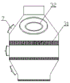
Fig. 4 is a schematic view of a demisting box in the multifunctional purification system of the present invention.
In the figure: the device comprises a spray box 1, a spray water pipe 11, a baffle 12, a sewage discharge outlet 13, a sewage discharge pipeline 14, a separation box 2, a water return port 21, a vertical partition plate 22, an oil removal tank 23, a buffer tank 24, an oil discharge tank 25, a sediment tank 26, a demisting box 3, a filter screen 31, a spray hot water pipe 32, an exhaust pipe 4, an exhaust fan 5, a circulating pump 6 and an observation hole 7.
Detailed Description
The present invention will be further explained with reference to the drawings and examples.
Example (b):
referring to fig. 1, a multifunctional purification system comprises a spray box 1, a separation box 2, a demisting box 3, an exhaust pipe 4 and an exhaust fan 5. Referring to fig. 2, both ends of the spray box 1 are respectively provided with an air inlet and an air outlet. A plurality of spray water pipes 11 are distributed in the spray box 1 along the length direction of the spray box 1, and the length direction of the spray water pipes 11 is vertical to the length direction of the spray box 1. The upper side of the spray header 11 is closely attached to the top plate of the spray box 1, and the lower side of the spray header is provided with a water outlet seam along the length direction of the spray header, so that water is sprayed out from the water outlet seam to form a water curtain. A plurality of baffles 12 are respectively arranged on the top plate and the bottom plate of the spray box 1 along the length direction of the spray box 1, and the baffles 12 on the top plate and the baffles 12 on the bottom plate are alternately distributed. In specific implementation, the lower side of the baffle plate 12 on the bottom plate of the spraying box 1 is bent towards the direction of the air inlet and extends to be connected with the bottom plate. Like this, baffle 12 that is located on the bottom plate is to keeping away from the air inlet direction protrusion for baffle 12 is stronger to blockking of air, has increased the dwell time of air in spray box 1, makes the contact time reinforcing of air and water, and purifying effect is better. Also be equipped with spray header 11 on baffle 12, spray header 11 orientation open the direction of air inlet has a water seam, like this, spray header 11 in the spray box 1 can carry out more abundant contact and wash with the air, further improves purifying effect. The baffle 12 on the bottom plate divides the bottom plate into a plurality of sections, and a drain outlet 13 is arranged on each section of the bottom plate. When in use, the sewage draining outlet 13 is distributed on one side of the baffle 12 close to the air inlet, so that sewage can be drained conveniently. A sewage discharge pipeline 14 is arranged below the spray box 1, one end of the sewage discharge pipeline 14 close to the air inlet is a sewage outlet, and the end of the sewage outlet is lower than the other end of the sewage discharge pipeline 14. Therefore, the sewage discharge pipeline 14 which is obliquely arranged enables the sewage positioned in the sewage discharge pipeline to flow to the sewage outlet through gravity, and the sewage can be smoothly discharged without an additional water pump, so that the energy is saved. Each drain 13 is respectively communicated with a drain pipeline 14 through a pipeline, so that sewage on each section of bottom plate can be discharged as soon as possible, and the risk of blockage between the drain 13 and the drain pipeline 14 is reduced.
The sewage generated in the spraying tank 1 enters the separation tank 2 through a sewage discharge pipeline 14 for separation. Referring to fig. 1, the separation tank 2 is located directly below the spray tank 1. Referring again to fig. 3, the separator tank 2 has a tank structure with an open top. A water return opening 21 is arranged at the position of the separation box 2 corresponding to the sewage outlet, and the sewage outlet extends into the water return opening 21. Thus, the sewage discharged from the shower box 1 directly enters the separation box 2. A plurality of vertical partition plates 22 are respectively distributed on the upper part and the lower part of the separation box 2 along the length direction. The upper vertical partition plates 22 and the lower vertical partition plates 22 are alternately distributed. A vertical partition 22 at the upper portion of the separator tank 2 partitions the upper portion of the separator tank 2 into a plurality of oil sumps 23. Wherein, the oil removal pool 23 close to the water return port is larger than the rest oil removal pools 23 to form a buffer pool 24. The sewage discharged from the drainage pipeline is fixed and enters the buffer pool 24 from the water return port 21, so that the sewage is buffered in the buffer pool 24 and then separated, and the design is reasonable. The vertical partition plate positioned at the lower part of the separation box 2 separates the lower part of the separation box 2 to form a plurality of sediment pools 26, and sewage after oil contamination separation moves towards one end of the separation box 2 far away from the buffer pool 24, so that dust in the sewage is precipitated in each sediment pool 26 and finally separated. An oil discharge groove 25 is respectively arranged in each oil removal pool 23, the upper side of the oil discharge groove 25 is an open side, and the upper side of the oil discharge groove 25 is lower than the upper side of the separation box 2 to form an oil inlet. In specific implementation, the length direction of the oil discharge groove 25 is consistent with the length direction of the separation box 2, and two ends of the oil discharge groove respectively extend to two sides of the oil removal tank 23. The oil discharge groove 25 is communicated with the oil discharge pipe through a pipeline, so that separated oil stains can be collected in a centralized manner.
The multi-functional purification system further comprises a circulation pump 6. The water inlet end of the circulating pump 6 is communicated with the upper part of the sediment tank 26 far away from the buffer tank 24 through a pipeline, and the water outlet end of the circulating pump is communicated with the spray water pipe 11. During specific implementation, a thermostat is further arranged between the circulating pump 6 and the spray water pipe 11, a water inlet of the thermostat is communicated with a water outlet of the circulating pump 6, and a water outlet of the thermostat is communicated with the spray water pipe 11. Thus, the hot water sprayed from the shower pipe 11 is more favorable for flushing away the oil molecules and odor in the air, and the oil molecules in the sewage entering the separation tank 2 are not solidified, thereby facilitating the separation of the oil stain.
Referring to fig. 4, the air outlet of the spraying box 1 is connected with one end of the demisting box 3. The defogging box 3 is vertically arranged, the upper end of the defogging box 3 is provided with a hot spray water pipe 32, and a filter screen 31 is arranged in the defogging box 3. During implementation, be equipped with three-layer filter screen 31 in the defogging case 3, filter screen 31 is the wire net, follows the thickness of supreme filter layer and increases gradually down. In this way, the resistance of the filter screen 31 to the air is gradually increased, and the air is further purified, thereby realizing secondary purification of the air. The oil smoke purified by the spray box 1 is washed by spray hot water and filtered by the filter screen 31 in the demisting box 3, so that oil molecules, odor and dust are thoroughly removed, and the discharged air meets the emission standard. After the hot spray water in the demisting tank 3 washes the air, the air flows downwards into the spray tank 1 and is discharged from the sewage outlet 13. In order to facilitate observation and maintenance, the spraying box 1 and the demisting box 3 are respectively provided with an observation hole 7. The other end of the demisting tank 3 is connected with the exhaust pipe 4. The exhaust fan 5 is positioned in one end of the exhaust pipe 4 far away from the demisting tank 3. When the multifunctional purification system works, the exhaust fan 5 works to form negative pressure in the exhaust pipe 4, air with oil smoke continuously enters the multifunctional purification system, and the purified air is discharged through the exhaust pipe 4.
Through distributing several shower pipes in the spray box for after the air that has the oil smoke gets into the spray box, can fully contact with shower pipe spun cascade, mix, thereby bring oil molecule, foul smell and dust in the air to the sewage as far as, realize once purifying to the air. And then the air is treated for the second time by a defogging box, and the discharged air is clean and has no oil molecules and odor. The upper part and the lower part of the separation box are respectively distributed with a plurality of vertical clapboards along the length direction, and the vertical clapboards separate the separation box to form an oil removing pool, a buffer pool and a sediment pool, so that the oil, the slag and the water are collected in a classified manner, the subsequent treatment is convenient, and the environmental protection is reliable. The water on the upper part of the sediment tank far away from the buffer tank is pumped into the spray water pipe through the circulating pump and the water pipe for cyclic utilization, so that the energy is saved and the environment is protected.
Finally, it should be noted that the above embodiments are only used for illustrating the technical solutions of the present invention and not for limiting the technical solutions, and those skilled in the art should understand that those modifications or equivalent substitutions can be made to the technical solutions of the present invention without departing from the spirit and scope of the technical solutions, and all should be covered in the scope of the claims of the present invention.
Claims (8)
1. A multifunctional purification system comprises a spraying box, a separation box, a demisting box, an exhaust pipe and an exhaust fan; the two ends of the spray box are respectively provided with an air inlet and an air outlet, the air outlet is connected with one end of the demisting box, and the other end of the demisting box is connected with the exhaust pipe; the exhaust fan is positioned in one end of the exhaust pipe, which is far away from the defogging box; the separation box is positioned right below the spraying box; it is characterized in that the preparation method is characterized in that,
a plurality of spray water pipes are distributed in the spray box along the length direction of the spray box, the length direction of each spray water pipe is vertical to the length direction of the spray box, and the lower side of each spray water pipe is provided with a water outlet seam along the length direction of the spray water pipe; a plurality of baffles are respectively arranged on the top plate and the bottom plate of the spray box along the length direction of the spray box, wherein the baffles on the top plate and the baffles on the bottom plate are alternately distributed; the baffle plate on the bottom plate divides the bottom plate into a plurality of sections, and each section of bottom plate is provided with a drain outlet; a sewage discharge pipeline is arranged below the spray box, a sewage outlet is arranged at one end of the sewage discharge pipeline close to the air inlet, and the end where the sewage outlet is located is lower than the other end of the sewage discharge pipeline; each sewage draining outlet is communicated with a sewage draining pipeline through a pipeline;
the separation box is of a box body structure with an open upper part, a water return port is arranged at the position of the separation box corresponding to the sewage outlet, and the sewage outlet extends into the water return port; a plurality of vertical partition plates are respectively distributed on the upper part and the lower part of the separation box along the length direction of the separation box, wherein the vertical partition plates on the upper part and the vertical partition plates on the lower part are alternately distributed; the vertical partition plate positioned at the upper part of the separation box divides the upper part of the separation box into a plurality of oil removal pools, wherein the oil removal pool close to the water return port is larger than the rest oil removal pools to form a buffer pool, and the vertical partition plate positioned at the lower part of the separation box divides the lower part of the separation box into a plurality of sediment pools; an oil discharge groove is respectively arranged in each oil removing pool, the upper side of each oil discharge groove is an open side, and the upper side of each oil discharge groove is lower than the upper side of the separation box to form an oil inlet; the oil discharge groove is communicated with the oil discharge pipe through a pipeline;
the water inlet end of the circulating pump is communicated with the upper part of the sediment tank far away from the buffer tank through a pipeline, and the water outlet end of the circulating pump is communicated with the spray water pipe.
2. The multi-functional purification system of claim 1, wherein the lower side of the baffle plate on the bottom plate of the spray tank is bent in the direction of the air inlet and extended to be connected to the bottom plate.
3. The multifunctional purification system as claimed in claim 1 or 2, wherein a spray pipe is also arranged on the baffle plate, and the spray pipe is provided with a water outlet slit towards the air inlet.
4. The multifunctional purification system as claimed in claim 1, wherein a thermostat is further provided between the circulation pump and the shower pipe, wherein the thermostat has a water inlet in communication with the water outlet of the circulation pump and a water outlet in communication with the shower pipe.
5. The multi-functional purification system of claim 1, wherein the oil drainage groove has a length direction corresponding to a length direction of the separation tank, and both ends of the oil drainage groove extend to both sides of the oil removal tank.
6. The multifunctional purification system according to claim 1, wherein the demisting tank is vertically arranged, and a filter screen is arranged in the demisting tank; the upper end of the demisting box is provided with a hot water spray pipe.
7. The multifunctional purification system of claim 1, wherein three layers of filter screens are arranged in the demisting tank, the filter screens are steel wire meshes, and the thickness of the filter layers is gradually increased from bottom to top.
8. The multi-functional purification system of claim 1, wherein the spray tank and the demisting tank are provided with a viewing port, respectively.
Priority Applications (1)
| Application Number | Priority Date | Filing Date | Title |
|---|---|---|---|
| CN201921519423.9U CN210729053U (en) | 2019-09-12 | 2019-09-12 | Multifunctional purification system |
Applications Claiming Priority (1)
| Application Number | Priority Date | Filing Date | Title |
|---|---|---|---|
| CN201921519423.9U CN210729053U (en) | 2019-09-12 | 2019-09-12 | Multifunctional purification system |
Publications (1)
| Publication Number | Publication Date |
|---|---|
| CN210729053U true CN210729053U (en) | 2020-06-12 |
Family
ID=71006778
Family Applications (1)
| Application Number | Title | Priority Date | Filing Date |
|---|---|---|---|
| CN201921519423.9U Active CN210729053U (en) | 2019-09-12 | 2019-09-12 | Multifunctional purification system |
Country Status (1)
| Country | Link |
|---|---|
| CN (1) | CN210729053U (en) |
Cited By (3)
| Publication number | Priority date | Publication date | Assignee | Title |
|---|---|---|---|---|
| CN111921306A (en) * | 2020-07-31 | 2020-11-13 | 常州多单微电子设备有限公司 | Oil smoke waste gas effluent disposal system |
| CN115773556A (en) * | 2021-08-05 | 2023-03-10 | 韦氏(苏州)医疗科技有限公司 | Clean Space Assurance System |
| CN119112533A (en) * | 2024-09-12 | 2024-12-13 | 南通大学附属医院 | A sterile transfer bed for burn patients |
-
2019
- 2019-09-12 CN CN201921519423.9U patent/CN210729053U/en active Active
Cited By (3)
| Publication number | Priority date | Publication date | Assignee | Title |
|---|---|---|---|---|
| CN111921306A (en) * | 2020-07-31 | 2020-11-13 | 常州多单微电子设备有限公司 | Oil smoke waste gas effluent disposal system |
| CN115773556A (en) * | 2021-08-05 | 2023-03-10 | 韦氏(苏州)医疗科技有限公司 | Clean Space Assurance System |
| CN119112533A (en) * | 2024-09-12 | 2024-12-13 | 南通大学附属医院 | A sterile transfer bed for burn patients |
Similar Documents
| Publication | Publication Date | Title |
|---|---|---|
| CN208279430U (en) | A kind of efficient air-floating processing oily waste water device | |
| CN113546497A (en) | Wet dust removal device and dust removal method | |
| CN218834061U (en) | Novel washing formula exhaust-gas treatment equipment | |
| CN108722092A (en) | A kind of Tower for purifying waste gas | |
| CN107998789A (en) | A kind of combustion tail gas fuel gas and dust processing equipment | |
| CN206881242U (en) | High efficiency oil-water separate tank | |
| CN202876631U (en) | Novel environment-friendly lampblack degradation and purification treatment system for catering kitchen | |
| CN2413183Y (en) | Filter screen water film cooking fume purifier | |
| CN2471399Y (en) | Oily smoke eliminator | |
| CN201175637Y (en) | Water curtain spray eliminator | |
| CN112093998A (en) | A treatment device for oily wastewater | |
| CN212632244U (en) | Multi-effect cyclone spray tower | |
| CN215822638U (en) | Comprehensive wet dust collector | |
| CN213610529U (en) | Stainless steel whirl tower exhaust-gas treatment equipment | |
| CN208340389U (en) | A kind of forming machine exhaust air deodorization system | |
| CN208959534U (en) | A kind of water tank dust collecting system | |
| CN212348194U (en) | Oil smoke purifier is used in edible oil cleaner production | |
| CN2675232Y (en) | Combined type oil fume desulfurizing and dust-removing purifier | |
| CN223800690U (en) | Flue gas cooling and purifying device of garbage incineration system | |
| CN221601588U (en) | Wet dust collector | |
| CN213610235U (en) | Circulating water structure applied to stainless steel cyclone tower waste gas treatment equipment | |
| CN213221436U (en) | Waste gas treatment recovery plant | |
| CN222585973U (en) | Asphalt fume treatment device for asphalt mixing station | |
| CN219646943U (en) | Sewage folded plate ecological treatment device | |
| CN111620499A (en) | Integrated treatment equipment for waste gas and waste water |
Legal Events
| Date | Code | Title | Description |
|---|---|---|---|
| GR01 | Patent grant | ||
| GR01 | Patent grant |