CN210723747U - Intelligent switch cabinet with network communication function - Google Patents
Intelligent switch cabinet with network communication function Download PDFInfo
- Publication number
- CN210723747U CN210723747U CN201921494562.0U CN201921494562U CN210723747U CN 210723747 U CN210723747 U CN 210723747U CN 201921494562 U CN201921494562 U CN 201921494562U CN 210723747 U CN210723747 U CN 210723747U
- Authority
- CN
- China
- Prior art keywords
- cabinet body
- side mouth
- control panel
- network communication
- communication function
- Prior art date
- Legal status (The legal status is an assumption and is not a legal conclusion. Google has not performed a legal analysis and makes no representation as to the accuracy of the status listed.)
- Expired - Fee Related
Links
- 239000000428 dust Substances 0.000 abstract description 3
- 239000007787 solid Substances 0.000 abstract description 2
- 238000010586 diagram Methods 0.000 description 1
- 238000012423 maintenance Methods 0.000 description 1
- 238000012986 modification Methods 0.000 description 1
- 230000004048 modification Effects 0.000 description 1
- 238000004092 self-diagnosis Methods 0.000 description 1
Images



Landscapes
- Distribution Board (AREA)
- Patch Boards (AREA)
Abstract
The utility model discloses an intelligent switch cabinet of network communication function, including the cabinet body, hinge, door, control panel, side mouth, fixed slide rail, electrical apparatus telescoping device, the cabinet body is the rectangle cabinet body, the cabinet body is preceding to have three door plant through hinge joint, control panel is installed to the door plant, the side mouth that has three equidistance is opened to cabinet body right flank, fixed slide rail, each are installed to side mouth underrun bolt the electrical apparatus telescoping device is installed respectively to the side mouth. The utility model discloses be convenient for pull out the electrical components in the solid, carry out the dust clearance, and convenient to detach changes and maintains, does not influence control panel's on the door plant normal use, and overall structure installs very conveniently, and the vent is convenient for air cycle, reduces cabinet internal portion temperature.
Description
Technical Field
The utility model relates to a cubical switchboard especially relates to an intelligent switch cabinet of network communication function.
Background
The intelligent switch cabinet is a cabinet with high performance, high reliability, certain self-diagnosis and automatic control performance and network communication capability. Intelligence cubical switchboard is darker, when clearance dust or dismantlement maintenance, very inconvenient, need open the door plant, dismantles the electrical part of inside, because the space is narrow and small, brings a great deal of inconvenience for the staff, and it is convenient inadequately to use.
SUMMERY OF THE UTILITY MODEL
An object of the utility model is to provide an intelligent switch cabinet of network communication function to solve above-mentioned technical problem.
In order to realize the purpose, the utility model adopts the following technical scheme:
the utility model provides an intelligent switch cabinet of network communication function, includes the cabinet body, hinge, door, control panel, side mouth, fixed slide rail, electrical apparatus telescoping device, the cabinet body is the rectangle cabinet body, the cabinet body is preceding to have three door plant through hinge joint, control panel is installed to the door plant, the side mouth that has three equidistance is opened to cabinet body right flank, fixed slide rail, each are installed to the side mouth underrun bolt the electrical apparatus telescoping device is installed respectively to the side mouth.
On the basis of the technical scheme, the electric appliance telescopic device comprises a bottom plate, a telescopic sliding strip, side plates, a vent, a handle, slots and a plug board, wherein the telescopic sliding strip is fixed on the bottom surface of the bottom plate, the telescopic sliding strip slides along the direction of the fixed sliding rail, the side plates are vertically fixed on the right side of the bottom plate, the vent is penetrated through the side plates, the handle is installed at the bottom of each side plate, two rows of slots are fixed on the front and the back of the top surface of the bottom plate respectively, and the plug board is plugged with the two rows of slots.
On the basis of the technical scheme, the plug board is used for installing electrical components, and the electrical components are respectively connected with control panels on the corresponding door plates through wires.
Compared with the prior art, the utility model has the advantages of it is following: the utility model discloses an electrical apparatus telescoping device can remove about, is convenient for pull out the electrical components in the solid, carries out the dust clearance, and convenient to detach changes and maintains, does not influence control panel's on the door plant normal use, and overall structure installs very conveniently, and the vent is convenient for air cycle, reduces the internal portion temperature of cabinet.
Drawings
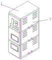
Fig. 1 is a front view of the present invention.
Fig. 2 is an appearance structure diagram of the present invention.
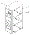
Fig. 3 is a schematic view of the appearance structure of the side opening of the present invention.
Fig. 4 is a schematic view of the connection of the electrical telescopic device of the present invention at the side opening.
Fig. 5 is a schematic view of the connection between the socket and the socket of the present invention.
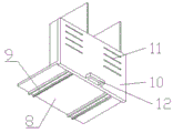
Fig. 6 is a schematic view of the appearance structure of the telescopic slide bar of the present invention.
In the figure: 1. the cabinet body, 2, hinge, 3, door plant, 4, control panel, 5, side mouth, 6, fixed slide rail, 7, electrical apparatus telescoping device, 8, bottom plate, 9, flexible draw runner, 10, curb plate, 11, vent, 12, handle, 13, slot, 14, picture peg.
Detailed Description
The invention is explained in further detail below with reference to the figures and the embodiments.
As shown in fig. 1-6, an intelligent switch cabinet with a network communication function comprises a cabinet body 1, a hinge 2, door panels 3, a control panel 4, side openings 5, fixed slide rails 6 and electric appliance expansion devices 7, wherein the cabinet body 1 is a rectangular cabinet body, the front of the cabinet body 1 is hinged with three door panels 3 through the hinge 2, the door panels 3 are provided with the control panel, the right side of the cabinet body 1 is provided with three equidistant side openings 5, the bottom surfaces of the side openings 5 are provided with the fixed slide rails 6 through bolts, and each side opening 5 is provided with the electric appliance expansion device 7.
Electric appliance telescoping device 7 includes bottom plate 8, flexible draw runner 9, curb plate 10, vent 11, handle 12, slot 13, picture peg 14, 8 bottom surface of bottom plate are fixed with flexible draw runner 9, flexible draw runner 9 slides along 6 directions of fixed slide rail, 8 right side vertical fixation of bottom plate has curb plate 10, curb plate 10 runs through there is vent 11, handle 12 is installed to curb plate 10 bottom, be fixed with two rows of slots 13, two around the 8 top surfaces of bottom plate respectively picture peg 14 is pegged graft with two rows of slots 13 respectively.
The plug boards 14 are used for installing electrical components, and the electrical components are respectively connected with the control panel 4 on the corresponding door panel 3 through wires.
The utility model discloses a theory of operation: the electric devices required in the cabinet body are installed through the screws in a plugging mode and connected with the control panel through the wires, when the electric devices are disassembled or maintained, the handle is pulled manually to pull the bottom plate out along the direction of the fixed sliding rail, and the electric devices on the inserting plate are exposed outside the cabinet body to be maintained.
The foregoing is a preferred embodiment of the present invention, and for those skilled in the art to understand the teaching of the present invention, the changes, modifications, replacements and variations to the embodiments will still fall within the protection scope of the present invention without departing from the principle and spirit of the present invention.
Claims (3)
1. The utility model provides an intelligent switch cabinet of network communication function, includes the cabinet body (1), hinge (2), door plant (3), control panel (4), side mouth (5), fixed slide rail (6), electrical apparatus telescoping device (7), its characterized in that: the cabinet body (1) is the rectangle cabinet body, the cabinet body (1) is preceding to have three door plant (3) through hinge (2) articulated, control panel is installed in door plant (3), side mouth (5) that have three equidistance are opened to the cabinet body (1) right flank, fixed slide rail (6), each are installed through the bolt to side mouth (5) underrun, electrical apparatus telescoping device (7) are installed respectively in side mouth (5).
2. The intelligent switch cabinet with network communication function as claimed in claim 1, wherein: electric appliance telescoping device (7) include bottom plate (8), flexible draw runner (9), curb plate (10), vent (11), handle (12), slot (13), picture peg (14), bottom plate (8) bottom surface is fixed with flexible draw runner (9), flexible draw runner (9) are followed fixed slide rail (6) direction and are slided, bottom plate (8) right side vertical fixation has curb plate (10), curb plate (10) run through there are vent (11), handle (12) are installed to curb plate (10) bottom, be fixed with two rows of slots (13) respectively around bottom plate (8) top surface, two picture peg (14) are pegged graft with two rows of slots (13) respectively.
3. The intelligent switch cabinet with network communication function as claimed in claim 2, wherein: the plug board (14) is used for installing electrical components, and the electrical components are respectively connected with the control panel (4) on the corresponding door panel (3) through wires.
Priority Applications (1)
| Application Number | Priority Date | Filing Date | Title |
|---|---|---|---|
| CN201921494562.0U CN210723747U (en) | 2019-09-10 | 2019-09-10 | Intelligent switch cabinet with network communication function |
Applications Claiming Priority (1)
| Application Number | Priority Date | Filing Date | Title |
|---|---|---|---|
| CN201921494562.0U CN210723747U (en) | 2019-09-10 | 2019-09-10 | Intelligent switch cabinet with network communication function |
Publications (1)
| Publication Number | Publication Date |
|---|---|
| CN210723747U true CN210723747U (en) | 2020-06-09 |
Family
ID=70937196
Family Applications (1)
| Application Number | Title | Priority Date | Filing Date |
|---|---|---|---|
| CN201921494562.0U Expired - Fee Related CN210723747U (en) | 2019-09-10 | 2019-09-10 | Intelligent switch cabinet with network communication function |
Country Status (1)
| Country | Link |
|---|---|
| CN (1) | CN210723747U (en) |
-
2019
- 2019-09-10 CN CN201921494562.0U patent/CN210723747U/en not_active Expired - Fee Related
Similar Documents
| Publication | Publication Date | Title |
|---|---|---|
| CN209282670U (en) | An anti-theft outdoor distribution box that is easy to maintain | |
| CN211046137U (en) | Distribution box convenient to maintain | |
| CN108390197A (en) | Daughter board connector, motherboard connector, photoelectric connector component and cabinet | |
| CN208608578U (en) | Safe power distribution box | |
| CN102623217A (en) | Rear-door interlocking mechanism for centrally-mounted switch cabinet | |
| CN202601451U (en) | Interlock mechanism of back door of mid-mounted switch cabinet | |
| CN213585079U (en) | A plug-in mechanism for a busway plug-in box | |
| CN218735644U (en) | Big data computer network safety device | |
| CN208010113U (en) | A kind of armoured switch cabinet door latch structure | |
| CN215735423U (en) | Waterproof type electrical apparatus box convenient to installation | |
| CN212486910U (en) | Communication integration constant temperature rack for 5G basic station | |
| CN212468144U (en) | Biological safety cabinet with extravehicular scanning equipment | |
| CN217427390U (en) | Automatically controlled cabinet convenient to remove inside electrical equipment | |
| CN209844280U (en) | Auxiliary opening device for high-low voltage complete cabinet | |
| CN218456247U (en) | Electric power cabinet for electric power work | |
| CN223023855U (en) | Switch cabinet convenient for mounting internal electric elements | |
| CN202602090U (en) | Local side plug-in frame device of high-voltage direct-current remote power feeding system, and cabinet | |
| CN210326562U (en) | Low-voltage intelligent switch cabinet | |
| CN220139972U (en) | Antistatic multifunctional electric control cabinet | |
| CN215528393U (en) | Electric cabinet for power engineering | |
| CN206775893U (en) | A kind of drawer type sub-control casing | |
| CN220732155U (en) | Switch cabinet convenient to overhaul | |
| CN219419955U (en) | Power distribution cabinet convenient to dismantle | |
| CN218070552U (en) | Novel cubical switchboard for electrical engineering | |
| CN213660967U (en) | Electrical control cabinet convenient to wiring |
Legal Events
| Date | Code | Title | Description |
|---|---|---|---|
| GR01 | Patent grant | ||
| GR01 | Patent grant | ||
| CF01 | Termination of patent right due to non-payment of annual fee |
Granted publication date: 20200609 Termination date: 20210910 |
|
| CF01 | Termination of patent right due to non-payment of annual fee |