CN210704177U - Steel pipe rust cleaning device that polishes for construction - Google Patents
Steel pipe rust cleaning device that polishes for construction Download PDFInfo
- Publication number
- CN210704177U CN210704177U CN201921766828.2U CN201921766828U CN210704177U CN 210704177 U CN210704177 U CN 210704177U CN 201921766828 U CN201921766828 U CN 201921766828U CN 210704177 U CN210704177 U CN 210704177U
- Authority
- CN
- China
- Prior art keywords
- steel pipe
- motor
- cabinet body
- fixed mounting
- motor box
- Prior art date
- Legal status (The legal status is an assumption and is not a legal conclusion. Google has not performed a legal analysis and makes no representation as to the accuracy of the status listed.)
- Expired - Fee Related
Links
- 229910000831 Steel Inorganic materials 0.000 title claims abstract description 50
- 239000010959 steel Substances 0.000 title claims abstract description 50
- JEIPFZHSYJVQDO-UHFFFAOYSA-N iron(III) oxide Inorganic materials O=[Fe]O[Fe]=O JEIPFZHSYJVQDO-UHFFFAOYSA-N 0.000 title claims abstract description 29
- 238000004140 cleaning Methods 0.000 title claims abstract description 12
- 238000010276 construction Methods 0.000 title claims abstract description 11
- 238000005498 polishing Methods 0.000 claims abstract description 24
- 230000005540 biological transmission Effects 0.000 claims abstract description 10
- 230000000694 effects Effects 0.000 claims abstract description 4
- 239000000428 dust Substances 0.000 claims description 21
- 241000883990 Flabellum Species 0.000 claims description 16
- 238000009435 building construction Methods 0.000 claims description 8
- 229910001172 neodymium magnet Inorganic materials 0.000 claims description 7
- XEEYBQQBJWHFJM-UHFFFAOYSA-N Iron Chemical compound [Fe] XEEYBQQBJWHFJM-UHFFFAOYSA-N 0.000 abstract description 40
- 229910052742 iron Inorganic materials 0.000 abstract description 19
- 230000033001 locomotion Effects 0.000 abstract description 5
- 230000002337 anti-port Effects 0.000 abstract description 2
- 238000000034 method Methods 0.000 description 5
- 238000004519 manufacturing process Methods 0.000 description 4
- 230000009471 action Effects 0.000 description 3
- VNWKTOKETHGBQD-UHFFFAOYSA-N methane Chemical compound C VNWKTOKETHGBQD-UHFFFAOYSA-N 0.000 description 2
- 230000008569 process Effects 0.000 description 2
- OKTJSMMVPCPJKN-UHFFFAOYSA-N Carbon Chemical compound [C] OKTJSMMVPCPJKN-UHFFFAOYSA-N 0.000 description 1
- 229910000975 Carbon steel Inorganic materials 0.000 description 1
- 230000004075 alteration Effects 0.000 description 1
- 230000009286 beneficial effect Effects 0.000 description 1
- 230000008901 benefit Effects 0.000 description 1
- 229910052799 carbon Inorganic materials 0.000 description 1
- 239000010962 carbon steel Substances 0.000 description 1
- 238000005553 drilling Methods 0.000 description 1
- 238000005516 engineering process Methods 0.000 description 1
- 239000012530 fluid Substances 0.000 description 1
- 239000000463 material Substances 0.000 description 1
- 238000012986 modification Methods 0.000 description 1
- 230000004048 modification Effects 0.000 description 1
- 239000003345 natural gas Substances 0.000 description 1
- 230000003647 oxidation Effects 0.000 description 1
- 238000007254 oxidation reaction Methods 0.000 description 1
- 230000000149 penetrating effect Effects 0.000 description 1
- 239000003209 petroleum derivative Substances 0.000 description 1
- 239000007787 solid Substances 0.000 description 1
- 239000000126 substance Substances 0.000 description 1
- 238000006467 substitution reaction Methods 0.000 description 1
Images


Landscapes
- Finish Polishing, Edge Sharpening, And Grinding By Specific Grinding Devices (AREA)
Abstract
The utility model relates to the technical field of construction equipment, and a steel pipe rust cleaning device that polishes for construction is disclosed, the intelligent cabinet temperature adjusting device comprises a cabinet body and a cabinet door, the middle part fixed mounting of cabinet body inner chamber bottom has the backup pad, fixed mounting has the slide between the top of backup pad right flank and the right flank of cabinet body inner chamber, the motor box has been placed at the top of slide, the inside fixed mounting of motor box has the rotating electrical machines, the one end of rotating electrical machines drive shaft runs through motor box and fixedly connected with is located the left three-jaw chuck of motor box. This steel pipe rust cleaning device that polishes for construction through the rotating electrical machines to opposite antiport, can produce sufficient friction between steel pipe and the wheel of polishing, through the slow rotation of control servo motor, servo motor's output shaft is connected through changeing board and gyro wheel and with the carriage release lever transmission, makes motor box reciprocating motion around on the slide, has realized carrying out the effect of polishing comprehensively to the steel pipe surface, and the iron rust on steel pipe surface is detached to the high efficiency.
Description
Technical Field
The utility model relates to a building apparatus technical field specifically is a steel pipe rust cleaning device that polishes for construction.
Background
The steel pipe is used for conveying fluid and powdery solid, exchanging heat energy, manufacturing mechanical parts and containers, and is also an economic steel, the development of the steel pipe production technology starts from the rise of the bicycle manufacturing industry, the development of the chemical industry, the drilling, production and transportation of petroleum and natural gas and the like all powerfully promote the development of the steel pipe industry on variety, yield and quality, and the application of the steel pipe in building construction is very wide.
The steel pipe is because the reason of its self material, especially the higher carbon steel pipe of carbon content receives the oxidation of oxide in the air very easily, make steel pipe surface produce rust stain, consequently need remove rust to the steel pipe, subsequent use of being convenient for, current steel pipe rust cleaning mode of polishing mainly is that the handheld portable polisher of workman is polished the rust cleaning to the steel pipe, this mode degree of labour is great, and need the artifical steel pipe round trip movement of holding, the inefficiency of polishing, and can not effectively detach the iron rust on steel pipe surface, can cause steel pipe surface unevenness, influence subsequent use and construction speed.
At the steel pipe in-process of polishing, the surface of steel pipe not only has rust, still depends on there are other debris, can produce a large amount of dust and iron fillings during polishing, and the iron fillings that fall when polishing and the dust that diffuses in the air have been caused to current grinding device can't collect, have caused the wasting of resources to pollute the surrounding environment.
SUMMERY OF THE UTILITY MODEL
Not enough to prior art, the utility model provides a steel pipe rust cleaning device that polishes for construction possesses high-efficient rust cleaning, collects the advantage of rust and dust, has solved the problem of proposing among the above-mentioned background art.
The utility model provides a following technical scheme: a steel pipe polishing and rust removing device for building construction comprises a cabinet body and a cabinet door, wherein a supporting plate is fixedly mounted in the middle of the bottom end of an inner cavity of the cabinet body, a slide way is fixedly mounted between the top of the right side face of the supporting plate and the right side face of the inner cavity of the cabinet body, a motor box is placed at the top of the slide way, a rotating motor is fixedly mounted in the motor box, one end of a driving shaft of the rotating motor penetrates through the motor box and is fixedly connected with a three-jaw chuck positioned on the left side of the motor box, a steel pipe is movably mounted on the left side of the three-jaw chuck, a connecting plate is fixedly mounted in the middle of the back face of the motor box, a slide groove is formed in the right side of the back face of the inner cavity of the cabinet body, a moving rod is placed in the slide groove, a moving groove penetrating forwards, the left end of the front face of the rotating plate is fixedly provided with a connecting column, the outer surface of the connecting column is movably sleeved with a roller, the bottom of the inner cavity of the cabinet body is fixedly provided with a motor base positioned on the left side of the supporting plate, the top of the motor base is fixedly provided with a double-shaft motor, the double-shaft motor is fixedly provided with a polishing wheel positioned below the steel pipe through one end of a driving shaft, the double-shaft motor is fixedly provided with a first fan blade through the other end of the driving shaft, the middle part of the left side face of the first fan blade is fixedly connected with a driving shaft, the other end of the driving shaft is fixedly provided with a second fan blade, the bottom of the side face of the cabinet body seat is fixedly communicated with a collecting pipe positioned on the left side of the second fan blade, the front face of the collecting pipe, and the left end of the collecting pipe is fixedly communicated with a dust collecting box.
Preferably, the top of the supporting plate and the top of the slide way are located on the same horizontal plane, grooves are formed in the top of the supporting plate and the top of the slide way, the width of each groove is the same as that of the motor box, and the length of each groove is the same as that of each slide way.
Preferably, the number of the sliding grooves is two, the length of the sliding grooves is the same as that of the moving grooves, and the length of the first fan blade is twice that of the rotating plate.
Preferably, the rotating plate is located in the middle of the sliding grooves in the horizontal direction, and the rotating plate is located in the middle of the two sliding grooves in the vertical direction.
Preferably, the inside of shifting chute has seted up the draw-in groove, and the spliced pole has been placed to the inside of draw-in groove, the diameter of spliced pole is less than the width of draw-in groove to be greater than the width of shifting chute.
Preferably, one end of the driving shaft of the double-shaft motor penetrates through the first fan blade and is fixedly connected with the left end of the transmission shaft, and the left end of the transmission shaft is fixedly connected with the second fan blade positioned at the right end of the inner side surface of the collecting pipe.
Compared with the prior art, the utility model discloses possess following beneficial effect:
1. this steel pipe rust cleaning device that polishes for construction, it is tight with the steel pipe clamp through the three-jaw chuck, the double-shaft motor drives and polishes the high-speed rotation of wheel and polishes with the steel pipe contact, through rotating electrical machines to opposite antiport, can produce sufficient friction between steel pipe and the wheel of polishing, be convenient for detach the iron rust, rotate slowly through control servo motor, servo motor's output shaft passes through commentaries on classics board and gyro wheel and is connected with the carriage release lever transmission, make motor box reciprocating motion around on the slide, the effect of polishing comprehensively is carried out to the steel pipe surface has been realized, the iron rust on steel pipe surface is detached to the high efficiency.
2. This steel pipe rust cleaning device that polishes for construction, it is rotatory to drive first flabellum and second flabellum through double-shaft motor, iron fillings and dust that first flabellum produced when will polishing blow off in time to the direction of second flabellum, through being located the inside second flabellum of collection pipe, blow iron fillings and dust to dust collection box, the doping is wherein put into iron fillings when advancing the connecting pipe, neodymium magnet adsorbs baffle department, remaining dust is collected through dust collection box, produced dust when not only having detached polishing, can also retrieve the iron fillings after polishing, the wasting of resources and polluted environment have been avoided.
Drawings
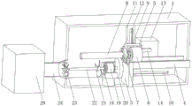
FIG. 1 is a schematic view of a half-section of a cabinet body of the present invention;
FIG. 2 is a schematic perspective view of the present invention;
FIG. 3 is a schematic view of a half-section of the movable rod of the present invention;
fig. 4 is a schematic view of the inner structure of the collecting tube of the present invention.
In the figure: 1. a cabinet body; 2. a cabinet door; 3. a support plate; 4. a slideway; 5. a motor box; 6. a rotating electric machine; 7. a three-jaw chuck; 8. a steel pipe; 9. a connecting plate; 10. a chute; 11. a travel bar; 12. a moving groove; 13. a servo motor; 14. rotating the plate; 15. connecting columns; 16. a roller; 17. a card slot; 18. a motor base; 19. a double-shaft motor; 20. grinding the wheel; 21. a first fan blade; 22. a drive shaft; 23. a second fan blade; 24. a collection pipe; 25. a connecting pipe; 26. a cylindrical sleeve; 27. a baffle plate; 28. a neodymium magnet; 29. a dust collection box.
Detailed Description
The technical solutions in the embodiments of the present invention will be described clearly and completely with reference to the accompanying drawings in the embodiments of the present invention, and it is obvious that the described embodiments are only some embodiments of the present invention, not all embodiments. Based on the embodiments in the present invention, all other embodiments obtained by a person skilled in the art without creative work belong to the protection scope of the present invention.
Referring to fig. 1-4, a steel pipe polishing and rust removing device for building construction comprises a cabinet body 1 and a cabinet door 2, wherein the left side of the back of the cabinet door 2 is movably mounted with the cabinet body 1 through a hinge arranged in the cabinet body 1, the cabinet door is convenient to open through a handle arranged on the front side of the cabinet door 2, and is provided with a steel pipe, a support plate 3 is fixedly mounted in the middle of the bottom end of an inner cavity of the cabinet body 1, a slideway 4 is fixedly mounted between the top of the right side surface of the support plate 3 and the right side surface of the inner cavity of the cabinet body 1, a motor box 5 is placed on the top of the slideway 4, a rotating motor 6 is fixedly mounted in the motor box 5, one end of a driving shaft of the rotating motor 6 penetrates through the motor box 5 and is fixedly connected with a three-jaw chuck 7 positioned on the left side of the motor box, a moving rod 11 is placed in the sliding groove 10, a moving groove 12 which penetrates through the front and the back is formed in the front of the moving rod 11, a servo motor 13 which is positioned behind the slideway 4 is fixedly installed on the back of the inner cavity of the cabinet body 1, a rotating plate 14 is fixedly connected to one end of the servo motor 13 through an output shaft, a connecting column 15 is fixedly installed at the left end of the front of the rotating plate 14, a roller 16 is movably sleeved on the outer surface of the connecting column 15, a motor base 18 which is positioned at the left side of the supporting plate 3 is fixedly installed at the bottom of the inner cavity of the cabinet body 1, a double-shaft motor 19 is fixedly installed at the top of the motor base 18, a polishing wheel 20 which is positioned below the steel pipe 8 is fixedly installed at one end of the double-shaft motor 19 through a driving shaft, a first fan blade 21 is, the bottom of the side of the cabinet body 1 is fixedly communicated with a collecting pipe 24 positioned on the left side of the second fan blade 23, the front of the collecting pipe 24 is fixedly communicated with a connecting pipe 25, the outer side surface of the connecting pipe 25 is connected with a cylindrical sleeve 26 through threads, the cylindrical sleeve 26 can be removed through anticlockwise rotation, the adsorbed iron filings are positioned on a baffle 27, the neodymium magnet 28 is taken down, the cylindrical sleeve 26 is turned downwards, the collected iron filings can be taken out conveniently and recycled, the baffle 27 is fixedly arranged inside the cylindrical sleeve 26, the neodymium magnet 28 is movably arranged on the front of the cylindrical sleeve 26, when the second fan blade 23 blows dust and iron filings to the collecting pipe 24, the iron filings are doped in the collecting pipe and adsorbed to the baffle 27 by the neodymium magnet 28 when entering the connecting pipe 25, the effect of separating the iron filings and the dust is realized, and a dust collecting box.
The top of the supporting plate 3 and the top of the slide way 4 are located on the same horizontal plane, the top of the supporting plate 3 and the top of the slide way 4 are provided with grooves, the width of each groove is the same as that of the motor box 5, and the length of each groove is the same as that of the corresponding sliding groove 10.
The number of the sliding grooves 10 is two, the length of the sliding grooves 10 is the same as that of the moving grooves 12, and the length of the first fan blade 21 is twice that of the rotating plate 14.
Wherein, the rotating plate 14 is located the middle part of spout 10 on the horizontal direction, and rotating plate 14 is located the centre of two spouts 10 on the vertical direction, and servo motor 13's output shaft passes through rotating plate 14 and gyro wheel 16 and is connected with the transmission of carriage release lever 11, and reciprocating motion is around the direction of spout 10 to carriage release lever 11, makes motor box reciprocating motion around on slide 4 for steel pipe 8 moves on grinding wheel 20 in rotatory, can carry out even comprehensive grinding to the steel pipe.
Wherein, draw-in groove 17 has been seted up to the inside of shifting chute 12, and spliced pole 15 has been placed to the inside of draw-in groove 17, and the diameter of spliced pole 15 is less than the width of draw-in groove 17 to be greater than the width of shifting chute 12.
Wherein, the one end of the 19 drive shafts of double-shaft motor runs through first flabellum 21 and with the left end fixed connection of transmission shaft 22, the left end fixed connection of transmission shaft 22 is located the second flabellum 23 of 24 medial surfaces right-hand members of collecting pipe, double-shaft motor 19 drives first flabellum 21 and second flabellum 23 is rotatory, dust and the iron rust that produces when in time will polishing blow to second flabellum 23 during first flabellum 21 is rotatory, blow dust and iron fillings to collecting pipe 24 through second flabellum 23, can in time discharge the dust and the iron fillings of the internal portion of cabinet 1.
The working principle is as follows:
when the cabinet door is used, the cabinet door 2 is opened, the steel pipe 8 is movably arranged on the left side of the three-jaw chuck 7, the double-shaft motor 19 and the rotating motor 6 are started and enabled to rotate in the opposite directions, the servo motor 13 is controlled to rotate slowly, the rotating plate 14 is driven to rotate, the roller 16 rolls in the clamping groove 17, the moving rod 11 is enabled to reciprocate back and forth along the direction of the sliding groove 10, the steel pipe 8 rotates and reciprocates back and forth, the double-shaft motor 19 drives the first fan blade 21 and the second fan blade 23 to rotate, dust and iron rust generated during polishing are blown to the collecting pipe 24, when iron chips are placed in the collecting pipe, the iron chips are adsorbed to the baffle 27 by the neodymium magnet 28 when entering the connecting pipe 25, and the rest dust is collected by the dust collecting.
It is noted that, herein, relational terms such as first and second, and the like may be used solely to distinguish one entity or action from another entity or action without necessarily requiring or implying any actual such relationship or order between such entities or actions. Also, the terms "comprises," "comprising," or any other variation thereof, are intended to cover a non-exclusive inclusion, such that a process, method, article, or apparatus that comprises a list of elements does not include only those elements but may include other elements not expressly listed or inherent to such process, method, article, or apparatus.
Although embodiments of the present invention have been shown and described, it will be appreciated by those skilled in the art that changes, modifications, substitutions and alterations can be made in these embodiments without departing from the principles and spirit of the invention, the scope of which is defined in the appended claims and their equivalents.
Claims (6)
1. The utility model provides a steel pipe rust cleaning device that polishes for construction, includes the cabinet body (1) and cabinet door (2), its characterized in that: the improved cabinet is characterized in that a supporting plate (3) is fixedly mounted in the middle of the bottom end of the inner cavity of the cabinet body (1), a slide (4) is fixedly mounted between the top of the right side face of the supporting plate (3) and the right side face of the inner cavity of the cabinet body (1), a motor box (5) is placed at the top of the slide (4), a rotating motor (6) is fixedly mounted in the motor box (5), one end of a driving shaft of the rotating motor (6) penetrates through the motor box (5) and is fixedly connected with a three-jaw chuck (7) positioned on the left side of the motor box (5), a steel pipe (8) is movably mounted on the left side of the three-jaw chuck (7), a connecting plate (9) is fixedly mounted in the middle of the back face of the motor box (5), a sliding groove (10) is formed in the right side of the back face of the inner cavity of the cabinet body (1), the back fixed mounting of the cabinet body (1) inner chamber has servo motor (13) that is located slide (4) rear, servo motor (13) has commentaries on classics board (14) through the one end fixedly connected with of output shaft, change the positive left end fixed mounting of board (14) and have spliced pole (15), gyro wheel (16) have been cup jointed in the surface activity of spliced pole (15), the bottom fixed mounting of the cabinet body (1) inner chamber has motor base (18) that is located backup pad (3) left side, the top fixed mounting of motor base (18) has double-shaft motor (19), double-shaft motor (19) have wheel (20) of polishing that is located steel pipe (8) below through the one end fixed mounting of drive shaft, double-shaft motor (19) have first flabellum (21) through the other end fixed mounting of drive shaft, first flabellum (21) left surface middle part fixedly connected with, the other end fixed mounting of transmission shaft (22) has second flabellum (23), the fixed intercommunication in bottom of the side is sat to the cabinet body (1) has and is located left collecting pipe (24) of second flabellum (23), the front fixed intercommunication of collecting pipe (24) has connecting pipe (25), there is cylinder cover (26) lateral surface of connecting pipe (25) through threaded connection, the inside fixed mounting of cylinder cover (26) has baffle (27), the front movable mounting of cylinder cover (26) has neodymium magnet (28), the left end fixed intercommunication of collecting pipe (24) has dust collection box (29).
2. The steel pipe polishing and rust removing device for building construction as claimed in claim 1, wherein: the top of backup pad (3) and the top of slide (4) are in same horizontal plane, the top of backup pad (3) and slide (4) is seted up flutedly, the width of recess is the same with the width of motor box (5), and the length of recess is the same with the length of spout (10).
3. The steel pipe polishing and rust removing device for building construction as claimed in claim 1, wherein: the number of the sliding grooves (10) is two, the length of the sliding grooves (10) is the same as that of the moving grooves (12), and the length of the first fan blades (21) is twice that of the rotating plate (14).
4. The steel pipe polishing and rust removing device for building construction as claimed in claim 1, wherein: the rotating plate (14) is located in the middle of the sliding grooves (10) in the horizontal direction, and the rotating plate (14) is located in the middle of the two sliding grooves (10) in the vertical direction.
5. The steel pipe polishing and rust removing device for building construction as claimed in claim 1, wherein: draw-in groove (17) have been seted up to the inside of shifting chute (12), and spliced pole (15) have been placed to the inside of draw-in groove (17), the diameter of spliced pole (15) is less than the width of draw-in groove (17) to be greater than the width of shifting chute (12).
6. The steel pipe polishing and rust removing device for building construction as claimed in claim 1, wherein: one end of a driving shaft of the double-shaft motor (19) penetrates through the first fan blade (21) and is fixedly connected with the left end of the transmission shaft (22), and the left end of the transmission shaft (22) is fixedly connected with the second fan blade (23) which is positioned at the right end of the inner side surface of the collecting pipe (24).
Priority Applications (1)
| Application Number | Priority Date | Filing Date | Title |
|---|---|---|---|
| CN201921766828.2U CN210704177U (en) | 2019-10-21 | 2019-10-21 | Steel pipe rust cleaning device that polishes for construction |
Applications Claiming Priority (1)
| Application Number | Priority Date | Filing Date | Title |
|---|---|---|---|
| CN201921766828.2U CN210704177U (en) | 2019-10-21 | 2019-10-21 | Steel pipe rust cleaning device that polishes for construction |
Publications (1)
| Publication Number | Publication Date |
|---|---|
| CN210704177U true CN210704177U (en) | 2020-06-09 |
Family
ID=70961670
Family Applications (1)
| Application Number | Title | Priority Date | Filing Date |
|---|---|---|---|
| CN201921766828.2U Expired - Fee Related CN210704177U (en) | 2019-10-21 | 2019-10-21 | Steel pipe rust cleaning device that polishes for construction |
Country Status (1)
| Country | Link |
|---|---|
| CN (1) | CN210704177U (en) |
Cited By (5)
| Publication number | Priority date | Publication date | Assignee | Title |
|---|---|---|---|---|
| CN111716223A (en) * | 2020-06-24 | 2020-09-29 | 徐州鸿祥机械制造有限公司 | Fine polishing equipment for metal pull rod |
| CN113235335A (en) * | 2021-04-27 | 2021-08-10 | 凤绍军 | Grinding device for closed steel rail milling and grinding vehicle |
| CN113561029A (en) * | 2021-09-24 | 2021-10-29 | 江苏淮海新材料科技有限公司 | Grinding device is used in maintenance of building engineering machine tool accessory |
| CN114535223A (en) * | 2022-03-01 | 2022-05-27 | 江苏润硕管业有限公司 | Recovery unit of plastic-coated tubular product is moulded to metal lining |
| CN115056101A (en) * | 2022-07-22 | 2022-09-16 | 惠州成高自动化科技有限公司 | Special-shaped pipe fitting polisher |
-
2019
- 2019-10-21 CN CN201921766828.2U patent/CN210704177U/en not_active Expired - Fee Related
Cited By (6)
| Publication number | Priority date | Publication date | Assignee | Title |
|---|---|---|---|---|
| CN111716223A (en) * | 2020-06-24 | 2020-09-29 | 徐州鸿祥机械制造有限公司 | Fine polishing equipment for metal pull rod |
| CN113235335A (en) * | 2021-04-27 | 2021-08-10 | 凤绍军 | Grinding device for closed steel rail milling and grinding vehicle |
| CN113561029A (en) * | 2021-09-24 | 2021-10-29 | 江苏淮海新材料科技有限公司 | Grinding device is used in maintenance of building engineering machine tool accessory |
| CN114535223A (en) * | 2022-03-01 | 2022-05-27 | 江苏润硕管业有限公司 | Recovery unit of plastic-coated tubular product is moulded to metal lining |
| CN114535223B (en) * | 2022-03-01 | 2022-11-25 | 江苏润硕管业有限公司 | Recovery unit of plastic-coated tubular product is moulded to metal lining |
| CN115056101A (en) * | 2022-07-22 | 2022-09-16 | 惠州成高自动化科技有限公司 | Special-shaped pipe fitting polisher |
Similar Documents
| Publication | Publication Date | Title |
|---|---|---|
| CN110900330A (en) | Full-automatic intelligent metal surface equipment of polishing | |
| CN210359481U (en) | Multi-station disc milling machine | |
| CN114273968A (en) | Carving mills machine with automatically cooling function | |
| CN209986746U (en) | Polishing equipment for steel plate machining | |
| CN210046298U (en) | Machine tool for machining unpowered roller set | |
| CN206839318U (en) | A kind of brake block fluting apparatus | |
| CN214685593U (en) | Pipe processing device | |
| CN211103139U (en) | Polishing device for production and processing of stainless steel plate | |
| CN109277926A (en) | A kind of mould steel processing derusting device | |
| CN221755637U (en) | A paper tube grinding machine for paper tube forming that is convenient for collecting waste scraps | |
| CN211728540U (en) | Milling machine convenient to retrieve coolant liquid | |
| CN113732806A (en) | Metal filing cleaning device for machining | |
| CN209223790U (en) | A kind of mould steel processing derusting device | |
| CN219837605U (en) | Ceramic polishing machine convenient to change polishing roller | |
| CN110900371A (en) | Grinding device for industrial machinery production | |
| CN214236433U (en) | Milling machine with cleaning function | |
| CN110970744A (en) | Processing equipment and processing method for ground rod | |
| CN213498597U (en) | Manual sand blasting machine suitable for optical lens production | |
| CN211966906U (en) | Recyclable polishing device for machining of sweeps | |
| CN223947581U (en) | Flat steel production is with equipment of polishing convenient to adjust | |
| CN215239798U (en) | A kind of plane grinding device of diamond composite sheet | |
| CN220074069U (en) | A kind of metal parts cutting dust collection device | |
| CN220880572U (en) | Automatic waste treatment mechanism of lathe | |
| CN213196778U (en) | Double-sided pipe machining grinding machine equipment | |
| CN216830106U (en) | Anti-ultraviolet wear-resistant lens processing and polishing device |
Legal Events
| Date | Code | Title | Description |
|---|---|---|---|
| GR01 | Patent grant | ||
| GR01 | Patent grant | ||
| CF01 | Termination of patent right due to non-payment of annual fee | ||
| CF01 | Termination of patent right due to non-payment of annual fee |
Granted publication date: 20200609 Termination date: 20211021 |