CN210702471U - Die-casting forming die - Google Patents
Die-casting forming die Download PDFInfo
- Publication number
- CN210702471U CN210702471U CN201921574490.0U CN201921574490U CN210702471U CN 210702471 U CN210702471 U CN 210702471U CN 201921574490 U CN201921574490 U CN 201921574490U CN 210702471 U CN210702471 U CN 210702471U
- Authority
- CN
- China
- Prior art keywords
- die
- fixed
- wall
- mold
- pipe
- Prior art date
- Legal status (The legal status is an assumption and is not a legal conclusion. Google has not performed a legal analysis and makes no representation as to the accuracy of the status listed.)
- Active
Links
Images


Landscapes
- Molds, Cores, And Manufacturing Methods Thereof (AREA)
Abstract
本实用新型属于压铸技术领域,且公开了一种压铸成型模具,包括定模,所述定模的上表壁中间位置处安装有模芯,所述定模内部且位于模芯的底端安装有蛇形冷却管,所述蛇形冷却管的一端连接有进水管,且蛇形冷却管远离进水管的一端连接有出水管,所述进水管和出水管均贯穿定模并延伸至其侧壁外部,所述定模上表壁的四个拐角处均连接有滑杆,本实用新型将蛇形冷却管铺设在模芯的底部进行换热,蛇形冷却管可增大模芯内的高温金属与冷水的接触面积和接触时间,可在冷水穿过定模的短暂时间内充分吸收热量,降温速度快,此外,冷却水换热后从出水管流出进行收集,再次降温处理后可重复使用,避免了水资源的浪费。
The utility model belongs to the technical field of die-casting, and discloses a die-casting molding die, which comprises a fixed die. A die core is installed at the middle position of the upper surface wall of the fixed die, and the fixed die is installed inside and at the bottom end of the die core. There is a serpentine cooling pipe, one end of the serpentine cooling pipe is connected with a water inlet pipe, and one end of the serpentine cooling pipe away from the water inlet pipe is connected with a water outlet pipe, the water inlet pipe and the water outlet pipe both penetrate the fixed mold and extend to its side Outside the wall, the four corners of the upper surface wall of the fixed mold are connected with sliding rods. The utility model lays a serpentine cooling pipe at the bottom of the mold core for heat exchange, and the serpentine cooling pipe can increase the cooling capacity in the mold core. The contact area and contact time between the high-temperature metal and the cold water can fully absorb the heat in the short time when the cold water passes through the fixed die, and the cooling speed is fast. In addition, the cooling water flows out from the outlet pipe for collection after heat exchange, and can be repeated after cooling again. use to avoid waste of water resources.
Description
技术领域technical field
本实用新型属于压铸技术领域,具体涉及一种压铸成型模具。The utility model belongs to the technical field of die casting, in particular to a die casting mould.
背景技术Background technique
压铸是一种金属铸造工艺,其特点是利用模具内腔对融化的金属施加高压,压铸特别适合制造大量的中小型铸件,因此压铸是各种铸造工艺中使用最广泛的一种,同其他铸造技术相比,压铸的表面更为平整,拥有更高的尺寸一致性。Die casting is a metal casting process, which is characterized by applying high pressure to the molten metal by using the inner cavity of the mold. Die casting is especially suitable for the manufacture of a large number of small and medium-sized castings. Therefore, die casting is the most widely used of various casting processes. Compared with technology, die casting has a flatter surface and higher dimensional consistency.
在专利号为CN201720239418.7的中国专利中,公开了一种压铸成型模具,该专利中描述到“通过循环水降温,缩短铸件的成型时间,提高铸件的质量”,但是该专利中循环水与模芯内的金属接触时间不够长,接触面积窄,无法充分热交换,降温效率低,此外,对文件中压铸成型模具未设置有效的导向结构,在压铸时容易产生偏差,造成产品不合格,只能返工重做或者摒弃,增加工作人员的工作量和造成资源的浪费。In the Chinese patent with the patent number of CN201720239418.7, a die-casting mold is disclosed. The patent describes that "the cooling of the castings by circulating water can shorten the molding time of the castings and improve the quality of the castings", but in the patent, the circulating water and the The metal contact time in the mold core is not long enough, the contact area is narrow, the heat exchange cannot be sufficient, and the cooling efficiency is low. In addition, there is no effective guide structure for the die-casting mold in the document, which is prone to deviation during die-casting, resulting in unqualified products. It can only be reworked or discarded, increasing the workload of the staff and causing waste of resources.
实用新型内容Utility model content
本实用新型的目的在于提供一种压铸成型模具,以解决上述背景技术中提出的对比文件中循环水与模芯内的金属接触时间不够长,接触面积窄,降温效率低的问题,此外,未设置有效的导向结构,在压铸时容易产生偏差的问题。The purpose of this utility model is to provide a kind of die-casting mould, in order to solve the problem that the contact time between circulating water and the metal in the mould core is not long enough, the contact area is narrow, and the cooling efficiency is low in the reference document proposed in the above-mentioned background art. An effective guide structure is provided, which is prone to deviation problems during die casting.
为实现上述目的,本实用新型提供如下技术方案:一种压铸成型模具,包括定模,所述定模的上表壁中间位置处安装有模芯,所述定模内部且位于模芯的底端安装有蛇形冷却管,所述蛇形冷却管的一端连接有进水管,且蛇形冷却管远离进水管的一端连接有出水管,所述进水管和出水管均贯穿定模并延伸至其侧壁外部,所述定模上表壁的四个拐角处均连接有滑杆,所述滑杆的顶端连接有第一安装板,所述第一安装板的顶端中间位置处安装有液压缸,所述液压缸的底端连接有液压伸缩杆,所述液压伸缩杆贯穿第一安装板并延伸至其下方,且液压伸缩杆的底端连接有压板,所述压板的上表壁四个拐角处均开设有与滑杆相匹配的通孔,且压板的下表壁固定有动模。In order to achieve the above purpose, the present utility model provides the following technical solutions: a die-casting mold, comprising a fixed mold, a mold core is installed at the middle position of the upper surface wall of the fixed mold, and the fixed mold is located inside and at the bottom of the mold core. A serpentine cooling pipe is installed at the end, one end of the serpentine cooling pipe is connected with a water inlet pipe, and one end of the serpentine cooling pipe away from the water inlet pipe is connected with a water outlet pipe, and both the water inlet pipe and the water outlet pipe pass through the fixed mold and extend to Outside the side wall, the four corners of the upper surface wall of the fixed die are connected with sliding rods, the top of the sliding rod is connected with a first mounting plate, and a hydraulic pressure is installed at the middle position of the top of the first mounting plate. The bottom end of the hydraulic cylinder is connected with a hydraulic telescopic rod, the hydraulic telescopic rod penetrates the first mounting plate and extends below it, and the bottom end of the hydraulic telescopic rod is connected with a pressure plate, the upper surface wall of the pressure plate is four Each corner is provided with a through hole matching the sliding rod, and a movable mold is fixed on the lower wall of the pressing plate.
优选的,所述定模上表壁且位于模芯的两侧对称固定有中空柱,所述中空柱的内部底部连接有导向柱,所述导向柱的外部套设有复位弹簧,所述动模的两侧壁对称连接有导向块,所述导向块的下表壁中间位置处开设有与导向柱相适配的导向槽,所述导向块下表壁且位于导向槽的外围开设有与中空柱相适配的通槽。Preferably, a hollow column is symmetrically fixed on the upper surface wall of the fixed die and located on both sides of the die core, the inner bottom of the hollow column is connected with a guide column, the outer part of the guide column is sleeved with a return spring, and the moving The two side walls of the die are symmetrically connected with guide blocks, the middle position of the lower wall of the guide block is provided with a guide groove that is adapted to the guide column, and the lower wall of the guide block is located on the periphery of the guide groove. Hollow column is suitable for the through groove.
优选的,所述导向槽的内壁粘接有消音棉层,所述消音棉层的内壁光滑无凸起。Preferably, the inner wall of the guide groove is bonded with a sound-absorbing cotton layer, and the inner wall of the sound-absorbing cotton layer is smooth without protrusions.
优选的,所述定模的底端固定有第二安装板,所述第二安装板的外表壁开设有安装孔。Preferably, the bottom end of the fixed mold is fixed with a second mounting plate, and the outer wall of the second mounting plate is provided with mounting holes.
优选的,所述液压缸的外部罩设有保护罩,所述保护罩的外表壁开设有散热孔。Preferably, the outer cover of the hydraulic cylinder is provided with a protective cover, and the outer wall of the protective cover is provided with cooling holes.
与现有技术相比,本实用新型的有益效果是:Compared with the prior art, the beneficial effects of the present utility model are:
(1)本实用新型将蛇形冷却管铺设在模芯的底部进行换热,蛇形冷却管可增大模芯内的高温金属与冷水的接触面积和接触时间,可在冷水穿过定模的短暂时间内充分吸收热量,提高热交换的效率,降温速度快,此外,冷却水换热后从出水管流出进行收集,再次降温处理后,可重复使用,避免了水资源的浪费。(1) The utility model lays a serpentine cooling pipe at the bottom of the mold core for heat exchange, and the serpentine cooling pipe can increase the contact area and contact time between the high-temperature metal in the mold core and the cold water, and can pass through the fixed mold in the cold water. It can fully absorb heat in a short period of time, improve the efficiency of heat exchange, and the cooling speed is fast. In addition, the cooling water flows out from the outlet pipe for collection after heat exchange, and can be reused after cooling again, avoiding the waste of water resources.
(2)本实用新型通过中空柱、导向柱、导向块和导向槽的配合,可在压铸时,保证动模和定模相吻合,防止压铸时产生偏差,保证了产品的合格率,避免了资源的浪费和增加返工的工作量,此外,通过复位弹簧可有效缓冲压铸时过大的压力,避免动定模间的撞击而损坏,延长了该模具的使用寿命。(2) Through the cooperation of the hollow column, the guide column, the guide block and the guide groove, the utility model can ensure that the movable die and the fixed die match during die casting, prevent deviation during die casting, ensure the qualified rate of the product, and avoid Waste of resources and increased workload of rework, in addition, the return spring can effectively buffer the excessive pressure during die casting, avoid damage caused by the impact between the movable and fixed dies, and prolong the service life of the die.
附图说明Description of drawings
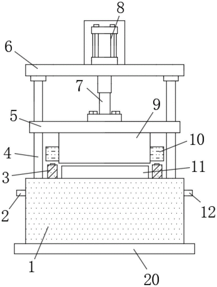
图1为本实用新型的结构示意图;Fig. 1 is the structural representation of the utility model;
图2为本实用新型中空柱的剖视图;Fig. 2 is the sectional view of the hollow column of the utility model;
图3为本实用新型导向块的仰视图;Fig. 3 is the bottom view of the utility model guide block;
图4为本实用新型定模的剖视图;Fig. 4 is the sectional view of the utility model fixed mold;
图5为本实用新型压板的俯视图;Fig. 5 is the top view of the utility model pressing plate;
图中:1-定模、2-进水管、3-中空柱、4-滑杆、5-压板、6-第一安装板、 7-液压伸缩杆、8-液压缸、9-动模、10-导向块、11-模芯、12-出水管、13- 导向柱、14-复位弹簧、15-通槽、16-消音棉层、17-导向槽、18-蛇形冷却管、 19-通孔、20-第二安装板。In the picture: 1-fixed die, 2-water inlet pipe, 3-hollow column, 4-slide rod, 5-pressing plate, 6-first mounting plate, 7-hydraulic telescopic rod, 8-hydraulic cylinder, 9-moving die, 10-Guide block, 11-Mold core, 12-Water outlet pipe, 13-Guide post, 14-Return spring, 15-Through groove, 16-Silence cotton layer, 17-Guide groove, 18-Snake cooling pipe, 19- Through hole, 20-Second mounting plate.
具体实施方式Detailed ways
下面将结合本实用新型实施例中的附图,对本实用新型实施例中的技术方案进行清楚、完整地描述,显然,所描述的实施例仅仅是本实用新型一部分实施例,而不是全部的实施例。基于本实用新型中的实施例,本领域普通技术人员在没有做出创造性劳动前提下所获得的所有其他实施例,都属于本实用新型保护的范围。The technical solutions in the embodiments of the present utility model will be clearly and completely described below with reference to the accompanying drawings in the embodiments of the present utility model. Obviously, the described embodiments are only a part of the embodiments of the present utility model, rather than all the implementations. example. Based on the embodiments of the present invention, all other embodiments obtained by those of ordinary skill in the art without creative work fall within the protection scope of the present invention.
请参阅图1-图5所示,本实用新型提供一种技术方案:一种压铸成型模具,包括定模1,定模1的上表壁中间位置处安装有模芯11,定模1内部且位于模芯11的底端安装有蛇形冷却管18,蛇形冷却管18的一端连接有进水管2,且蛇形冷却管18远离进水管2的一端连接有出水管12,进水管2和出水管12均贯穿定模1并延伸至其侧壁外部,在压铸后,可将冷却水从进水管2通入,进而经过蛇形冷却管18进行换热,蛇形冷却管18可增大模芯11内的高温金属与冷水的接触面积和接触时间,可在冷水穿过定模1的短暂时间内充分吸收热量,提高热交换的效率,换热后的冷水从出水管12流出,进行收集冷却后可重复使用,节约了水资源,定模1上表壁的四个拐角处均连接有滑杆4,滑杆4的顶端连接有第一安装板6,第一安装板6的顶端中间位置处安装有液压缸8,液压缸8的底端连接有液压伸缩杆7,液压伸缩杆7贯穿第一安装板6并延伸至其下方,且液压伸缩杆7的底端连接有压板5,压板5 的上表壁四个拐角处均开设有与滑杆4相匹配的通孔19,且压板5的下表壁固定有动模9。Please refer to FIG. 1 to FIG. 5 , the present invention provides a technical solution: a die-casting mold, including a fixed
进一步地,定模1上表壁且位于模芯11的两侧对称固定有中空柱3,中空柱3的内部底部连接有导向柱13,导向柱13的外部套设有复位弹簧14,动模9的两侧壁对称连接有导向块10,导向块10的下表壁中间位置处开设有与导向柱13相适配的导向槽17,导向块10下表壁且位于导向槽17的外围开设有与中空柱3相适配的通槽15,在压铸时,下压动模9可使中空柱3插设进入导向块10下表壁开设的通槽15内,保证动模9和定模1相吻合,防止压铸时产生偏差,保证了产品的合格率,此外,压铸时,复位弹簧14收缩,产生的反向弹力可有效缓冲压铸时过大的压力,降低对模具造成的损坏。Further, a
进一步地,导向槽17的内壁粘接有消音棉层16,消音棉层16的内壁光滑无凸起,消音棉层16的粘接可以减低压铸时挤压产生的声音,降低噪音污染。Further, the inner wall of the
进一步地,定模1的底端固定有第二安装板20,第二安装板20的外表壁开设有安装孔,通过开设有安装孔的第二安装板20,可将该磨具稳定安装起来,避免运行时产生晃动。Further, the bottom end of the fixed
进一步地,液压缸8的外部罩设有保护罩,保护罩的外表壁开设有散热孔,保护罩可以有效保护液压缸8,避免液压缸8的磕碰损坏,其中开设的散热孔便于液压缸8运行时热量的散出。Further, the outer cover of the
本实用新型的工作原理及使用流程:该实用新型在使用时,工作人员先将待压的高温液态金属注入模芯11内,然后利用液压缸8的液压运动驱动液压伸缩杆7伸缩,进而带动开设有通孔19的压板5顺着滑杆4下移,从而将动模9贴合定模1进行压铸,在压铸时,下压动模9可使中空柱3插设进入导向块10下表壁开设的通槽15内,同时使导向柱13插设进导向槽17内,保证动模9和定模1相吻合,防止压铸时产生偏差,避免了资源的浪费和增加返工的工作量,此外,压铸时,复位弹簧14处于收缩状态,产生的反向弹力可有效缓冲压铸时过大的压力,此外,在压铸后,可将冷却水从进水管2 通入,而后经由蛇形冷却管18进行换热,通过蛇形冷却管18可增大模芯11 内的高温金属与冷水的接触面积和接触时间,提高热交换的效率。The working principle and use process of the utility model: when the utility model is in use, the staff first injects the high-temperature liquid metal to be pressed into the
尽管已经示出和描述了本实用新型的实施例,对于本领域的普通技术人员而言,可以理解在不脱离本实用新型的原理和精神的情况下可以对这些实施例进行多种变化、修改、替换和变型,本实用新型的范围由所附权利要求及其等同物限定。Although the embodiments of the present invention have been shown and described, it will be understood by those skilled in the art that various changes and modifications can be made to these embodiments without departing from the principles and spirit of the present invention , alternatives and modifications, the scope of the present invention is defined by the appended claims and their equivalents.
Claims (5)
Priority Applications (1)
| Application Number | Priority Date | Filing Date | Title |
|---|---|---|---|
| CN201921574490.0U CN210702471U (en) | 2019-09-21 | 2019-09-21 | Die-casting forming die |
Applications Claiming Priority (1)
| Application Number | Priority Date | Filing Date | Title |
|---|---|---|---|
| CN201921574490.0U CN210702471U (en) | 2019-09-21 | 2019-09-21 | Die-casting forming die |
Publications (1)
| Publication Number | Publication Date |
|---|---|
| CN210702471U true CN210702471U (en) | 2020-06-09 |
Family
ID=70939617
Family Applications (1)
| Application Number | Title | Priority Date | Filing Date |
|---|---|---|---|
| CN201921574490.0U Active CN210702471U (en) | 2019-09-21 | 2019-09-21 | Die-casting forming die |
Country Status (1)
| Country | Link |
|---|---|
| CN (1) | CN210702471U (en) |
Cited By (3)
| Publication number | Priority date | Publication date | Assignee | Title |
|---|---|---|---|---|
| CN112872328A (en) * | 2021-01-25 | 2021-06-01 | 周旭明 | Die casting device for low-pressure casting machine shell |
| CN113579666A (en) * | 2021-08-06 | 2021-11-02 | 滁州市永达机械科技有限公司 | Novel refrigerator door body forming die and machining method thereof |
| CN115055662A (en) * | 2022-07-06 | 2022-09-16 | 广东鸿特精密技术(台山)有限公司 | Extrusion vibration die-casting device |
-
2019
- 2019-09-21 CN CN201921574490.0U patent/CN210702471U/en active Active
Cited By (5)
| Publication number | Priority date | Publication date | Assignee | Title |
|---|---|---|---|---|
| CN112872328A (en) * | 2021-01-25 | 2021-06-01 | 周旭明 | Die casting device for low-pressure casting machine shell |
| CN112872328B (en) * | 2021-01-25 | 2022-08-19 | 佛山市三越机械有限公司 | Die casting device for low-pressure casting machine shell |
| CN113579666A (en) * | 2021-08-06 | 2021-11-02 | 滁州市永达机械科技有限公司 | Novel refrigerator door body forming die and machining method thereof |
| CN115055662A (en) * | 2022-07-06 | 2022-09-16 | 广东鸿特精密技术(台山)有限公司 | Extrusion vibration die-casting device |
| CN115055662B (en) * | 2022-07-06 | 2024-05-14 | 广东鸿特精密技术(台山)有限公司 | Extrusion vibration die casting device |
Similar Documents
| Publication | Publication Date | Title |
|---|---|---|
| CN118847925A (en) | Be used for stainless steel abnormal shape piece casting device | |
| CN209598177U (en) | A kind of easily demoulding die device | |
| CN209969358U (en) | A high-precision stamping die suitable for continuous die stamping | |
| CN217666345U (en) | A mold cooling device for metal casting | |
| CN219074296U (en) | A rough casting mold for mechanical parts that is easy to demould | |
| CN212469720U (en) | Circulative cooling casting mould | |
| CN211840114U (en) | A mold release device for casting molds | |
| CN209925079U (en) | Corrosion-resistant cooler | |
| CN216550124U (en) | A high-efficiency punching device for crystal glass | |
| CN119282038A (en) | A casting mold for processing planetary flange castings | |
| CN221722274U (en) | Device for casting mold heat dissipation material | |
| CN209407353U (en) | A kind of copper carving casting mould | |
| CN215703367U (en) | Integrated valve fixing plate forming die | |
| CN216065491U (en) | Casting mold for nodular iron castings | |
| CN216461656U (en) | A die-casting device with support structure for castings | |
| CN208178392U (en) | A kind of machine die with refrigerating function | |
| CN221912851U (en) | A double-station forming mold for a rubber protective cover | |
| CN220970720U (en) | Die casting die | |
| CN207724745U (en) | A front mold core with good injection molding effect | |
| CN217223556U (en) | Production die for automobile oil pipe joint | |
| CN216937994U (en) | Stamping composite die convenient for demolding | |
| CN217192438U (en) | Quick casting forming device for shaft | |
| CN218934946U (en) | Large curved surface structure casting | |
| CN219381444U (en) | Injection mold | |
| CN219581641U (en) | Aluminum product easy demoulding mould |
Legal Events
| Date | Code | Title | Description |
|---|---|---|---|
| GR01 | Patent grant | ||
| GR01 | Patent grant | ||
| PE01 | Entry into force of the registration of the contract for pledge of patent right |
Denomination of utility model: A type of die-casting mold Granted publication date: 20200609 Pledgee: WEBANK Co.,Ltd. Pledgor: Shenzhen Shunming Taikang Precision Die Casting Co.,Ltd. Registration number: Y2024980049270 |
|
| PE01 | Entry into force of the registration of the contract for pledge of patent right | ||
| PC01 | Cancellation of the registration of the contract for pledge of patent right |
Granted publication date: 20200609 Pledgee: WEBANK Co.,Ltd. Pledgor: Shenzhen Shunming Taikang Precision Die Casting Co.,Ltd. Registration number: Y2024980049270 |
|
| PC01 | Cancellation of the registration of the contract for pledge of patent right |