CN210701604U - Dust collecting structure for air purification - Google Patents
Dust collecting structure for air purification Download PDFInfo
- Publication number
- CN210701604U CN210701604U CN201920306390.3U CN201920306390U CN210701604U CN 210701604 U CN210701604 U CN 210701604U CN 201920306390 U CN201920306390 U CN 201920306390U CN 210701604 U CN210701604 U CN 210701604U
- Authority
- CN
- China
- Prior art keywords
- dust
- air inlet
- air
- chamber
- dust collecting
- Prior art date
- Legal status (The legal status is an assumption and is not a legal conclusion. Google has not performed a legal analysis and makes no representation as to the accuracy of the status listed.)
- Active
Links
- 239000000428 dust Substances 0.000 title claims abstract description 95
- 238000004887 air purification Methods 0.000 title claims abstract description 24
- 239000003205 fragrance Substances 0.000 claims abstract description 21
- 235000017166 Bambusa arundinacea Nutrition 0.000 claims abstract description 7
- 235000017491 Bambusa tulda Nutrition 0.000 claims abstract description 7
- 241001330002 Bambuseae Species 0.000 claims abstract description 7
- 235000015334 Phyllostachys viridis Nutrition 0.000 claims abstract description 7
- 239000011425 bamboo Substances 0.000 claims abstract description 7
- XLYOFNOQVPJJNP-UHFFFAOYSA-N water Substances O XLYOFNOQVPJJNP-UHFFFAOYSA-N 0.000 claims description 21
- 230000001681 protective effect Effects 0.000 claims description 13
- 239000007921 spray Substances 0.000 claims description 13
- 238000007789 sealing Methods 0.000 claims description 11
- 239000007788 liquid Substances 0.000 claims description 10
- 230000035939 shock Effects 0.000 abstract description 9
- 239000013618 particulate matter Substances 0.000 abstract description 3
- 230000002349 favourable effect Effects 0.000 abstract description 2
- 230000006641 stabilisation Effects 0.000 abstract description 2
- 238000011105 stabilization Methods 0.000 abstract description 2
- 238000009434 installation Methods 0.000 abstract 3
- 238000010521 absorption reaction Methods 0.000 description 4
- 238000013016 damping Methods 0.000 description 4
- 238000000746 purification Methods 0.000 description 3
- 241000883990 Flabellum Species 0.000 description 2
- 238000001914 filtration Methods 0.000 description 2
- 239000010419 fine particle Substances 0.000 description 2
- 238000000034 method Methods 0.000 description 2
- 230000004075 alteration Effects 0.000 description 1
- 230000009286 beneficial effect Effects 0.000 description 1
- 230000000903 blocking effect Effects 0.000 description 1
- 230000007547 defect Effects 0.000 description 1
- 230000000249 desinfective effect Effects 0.000 description 1
- 230000007613 environmental effect Effects 0.000 description 1
- 239000003344 environmental pollutant Substances 0.000 description 1
- 230000004630 mental health Effects 0.000 description 1
- 238000012986 modification Methods 0.000 description 1
- 230000004048 modification Effects 0.000 description 1
- 231100000719 pollutant Toxicity 0.000 description 1
- 230000002285 radioactive effect Effects 0.000 description 1
- 239000000779 smoke Substances 0.000 description 1
- 238000004659 sterilization and disinfection Methods 0.000 description 1
- 238000006467 substitution reaction Methods 0.000 description 1
- 239000002351 wastewater Substances 0.000 description 1
Images


Landscapes
- Disinfection, Sterilisation Or Deodorisation Of Air (AREA)
- Filtering Of Dispersed Particles In Gases (AREA)
Abstract
The utility model discloses a dust collecting structure for air purification, including the mounting panel, four corners in the rear side of mounting panel all are equipped with the installation screw, and the equal threaded connection in inside of four installation screws has the installation screw, and the left front side of mounting panel is connected with the side of an air inlet section of thick bamboo, and the inboard left end of an air inlet section of thick bamboo is passed through the bearing and is connected the outside rotation of ring and be connected, and the inboard outside of connecting the loading board that passes through the link of an air inlet section of thick bamboo, the inside right side of loading board is equipped with the motor. This dust collecting structure for air purification can improve air purification and collection dirt efficiency, can the protection architecture can not be damaged by tiny particulate matter etc. protect the staff simultaneously, can prevent that the dust from getting into the gap, can carry out the shock attenuation, improve job stabilization nature, can make the moist weight that becomes of dust in the air to fall, can prevent to block up, can carry out multistage collection dirt, avoid the dust to collect incompletely, can make the air after the dust removal have fragrance, be favorable to air purification and collection dirt work.
Description
Technical Field
The utility model relates to an air purification equipment technical field specifically is a dust collecting structure for air purification.
Background
Air purification means to provide the disinfection of disinfecting to indoor various environmental problems, the dust fall removes the haze, dispel whole solutions such as harmful fitment is remained and peculiar smell, effective air-purifying can improve the life, the office condition, promote physical and mental health, the main pollution sources of purification include radioactive gas, mould, the particulate matter, the fitment is remained, second-hand smoke etc., need take different purification methods to different pollutants, and in air purification process, at first need remove dust, current dust removal structure air flow is slow, cause air purification inefficiency, the dust can get into the gap simultaneously, damage collection dirt and air purification structure, the dust is swung easily when collecting, cause the pollution, can not carry out multistage collection dirt, lead to the dust to collect incompletely.
SUMMERY OF THE UTILITY MODEL
The to-be-solved technical problem of the utility model is to overcome current defect, provide a dust collecting structure for air purification, the air flow is fast, and purification efficiency and dust collection efficiency are high, can prevent that the dust from damaging and blocking up dust collecting structure, can not swing after the dust is collected, avoid causing the pollution, can effectively solve the problem in the background art.
In order to achieve the purpose, the utility model provides the following technical scheme, the dust collecting structure for air purification comprises a mounting plate, wherein four corners of the rear side of the mounting plate are respectively provided with a mounting screw hole, and the insides of the four mounting screw holes are respectively in threaded connection with a mounting screw; it is characterized by also comprising an air inlet device, a dust collecting device and a water supply device;
the air inlet device comprises an air inlet cylinder, a connecting ring, a dustproof protective cover, a connecting circular plate, an arc-shaped fan blade, a motor, a bearing plate and a connecting frame; the air inlet cylinder is hollow inside and is internally provided with a bearing plate; the center of the bearing plate is provided with a hole and the motor, and the outer edge of the bearing plate is provided with a connecting frame connected with the inner wall of the air inlet cylinder; the connecting circular plate is arranged inside the air inlet cylinder, the center of one side surface of the connecting circular plate is connected with an output shaft of the motor, and a plurality of arc-shaped fan blades are uniformly distributed on the other side surface of the connecting circular plate along the outer edge of the side surface of the connecting circular plate; a dustproof protective cover is sleeved at the end part of the air inlet cylinder; a connecting ring is arranged inside the air inlet cylinder and is positioned between the dustproof protective cover and the arc-shaped fan blades;
the dust collecting device comprises a dust removing chamber and a dust collecting chamber; the dust chamber is hollow and is connected with the bottom of the air inlet cylinder, the dust chamber is connected below the dust chamber, one side of the dust chamber is open and is internally provided with a plurality of filter plates which are parallel to each other, the side surfaces of the filter plates are connected with square sealing covers capable of sealing the opening of the dust chamber, the dust chamber also comprises a plurality of groups of slide rails, and the filter plates are arranged on the slide rails;
the water supply device comprises a storage platform, a water storage tank, a liquid pump, a guide pipe, an annular pipe and a spray head; the object placing table is positioned below the air inlet drum, the surface of the object placing table is provided with a water storage tank and a filter pump, and the filter pump is connected with the water storage tank; the annular pipe is arranged between the air inlet barrel and the dust chamber, the annular pipe is provided with a spray head, the working end of the spray head is positioned in the dust chamber, and the annular pipe is connected with the liquid pump through a guide pipe;
the incense device is connected with one end face of the dust removal chamber, the air inlet cylinder, the dust removal chamber, the dust collection chamber and the surface which is fixed on the mounting plate are fixed, and the diameter of the connecting ring is smaller than the inner diameter of the air inlet cylinder.
Preferably, the left side of clean room is connected with the right side of an air inlet section of thick bamboo through the shock attenuation telescopic link of two parallels respectively, the side of shock attenuation telescopic link is equipped with the damping spring of spiral distribution.
Preferably, a protection cylinder is arranged on the side surface of the spray head positioned in the dust removing chamber, and a water outlet hole is formed in the right side of the protection cylinder.
Preferably, the fragrance sending device comprises an air outlet channel, a filter cylinder, a fragrance core, a circular sealing cover, a fragrance sending chamber and an air outlet; the left side of perfuming chamber is connected with the clean room, the one end of air-out passageway and the right side upper end intercommunication of clean room, the other end of air-out passageway and the top intercommunication of perfuming chamber, the inboard of perfuming chamber is equipped with the cartridge filter, the bottom of perfuming chamber is equipped with the air outlet, the inside of cartridge filter is equipped with fragrant core, the right side of fragrant core is equipped with circular sealed lid.
Preferably, all be equipped with evenly distributed's filtration hole on the three filter, and the filtration hole from the top down on the three filter reduces in proper order.
Compared with the prior art, the beneficial effects of the utility model are that, this dust collecting structure for air purification, easy and simple to handle, can improve the air admission speed through arranging of arc flabellum, improve air purification and dust collection efficiency, can protective structure can not be damaged by tiny particulate matter etc. through dustproof safety cover, protect the staff simultaneously, can prevent through the loading board that the dust from getting into the gap, damage structure, can carry out the shock attenuation through damping spring and shock attenuation telescopic link, improve job stabilization nature, can make the moist weight of dust in the air through the shower nozzle, thereby fall, can prevent to block up through a protection section of thick bamboo, can carry out multistage collection dirt through the filter, it is incomplete to avoid the dust to collect, send out the air that fragrant device can make after the dust removal to have fragrance, be favorable to air purification and dust.
Drawings
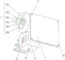
FIG. 1 is a schematic structural view of the present invention;
FIG. 2 is a schematic front view of the present invention;
fig. 3 is a schematic view of the rear view structure of the present invention.
In the figure, 1 mounting plate 1, 2 damping spring, 3 mounting screw hole, 4 damping telescopic rod, 5 annular tube, 6 protection cylinder, 7 fragrance emitting device, 701 air outlet channel, 702 filter cylinder, 703 fragrance core, 704 round sealing cover, 705 fragrance emitting chamber, 706 air outlet, 8 dust removing chamber, 9 dust collecting chamber, 10 square sealing cover, 11 filter plate, 12 conduit, 13 bearing plate, 14 object placing table, 15 arc fan blade, 16 mounting screw, 17 water storage tank, 18 connecting circular plate, 19 dust protection cover, 20 connecting circular ring, 21 air inlet cylinder, 22 connecting frame, 23 spray head, 24 valve, 25 liquid pump, 26 motor, 27 control switch group and 28 slide rail.
Detailed Description
The technical solutions in the embodiments of the present invention will be described clearly and completely with reference to the accompanying drawings in the embodiments of the present invention, and it is obvious that the described embodiments are only some embodiments of the present invention, not all embodiments. Based on the embodiments in the present invention, all other embodiments obtained by a person skilled in the art without creative work belong to the protection scope of the present invention.
Referring to fig. 1-3, the present invention provides a technical solution, a dust collecting structure for air purification, including a mounting plate 1, four corners of the rear side of the mounting plate 1 are all provided with mounting screw holes 3, the inside of the four mounting screw holes 3 is all connected with mounting screws 16 by screw threads, the left front side of the mounting plate 1 is connected with the side surface of an air inlet cylinder 21, the left end of the inner side of the air inlet cylinder 21 is rotatably connected with the outer side of a connecting ring 20 by a bearing, the inner side of the air inlet cylinder 21 is connected with the outer side of a bearing plate 13 by a connecting frame 22, which can prevent dust from entering into gaps, damage the structure, the right side of the inner part of the bearing plate 13 is provided with a motor 26, the output shaft of the motor 26 passes through the left side of the bearing plate 13 to be connected with the right center of the connecting circular plate 18, arc-shaped fan blades 15 are arranged between the, the air purification and dust collection efficiency is improved, the dust-proof protective cover 19 is arranged on the left side of the air inlet cylinder 21, the protective structure can not be damaged by fine particles and the like, and meanwhile workers are protected, the right funnel opening of the air inlet cylinder 21 is communicated with the left center of the dust chamber 8, the left side of the dust chamber 8 is connected with the right side of the air inlet cylinder 21 through two parallel shock absorption telescopic rods 4, the side surfaces of the shock absorption telescopic rods 4 are provided with shock absorption springs 2 which are distributed spirally, shock absorption can be carried out, the working stability is improved, the rear side of the dust chamber 8 is connected with the mounting plate 1, the left side inside the dust chamber 8 is provided with four spray heads 23 which are distributed along the left side of the dust chamber 8 at equal angles, the dust in the air can be moistened and become heavy, and accordingly falls, the protective cylinder 6 is arranged on the side surface of the spray head, the left side of the dust removal chamber 8 is provided with a ring-shaped pipe 5, the left front side of the mounting plate 1 is provided with a placing table 14, the placing table 14 is respectively provided with a water storage tank 17 and a liquid pump 25, an input port of the liquid pump 25 is connected with an output port of the water storage tank 17 through a guide pipe 12, an output port of the liquid pump 25 is connected with an input port at the bottom of the ring-shaped pipe 5 through a guide pipe 12, four output ports at the right side of the ring-shaped pipe 5 are respectively connected with input ports of four spray heads 23, the right side of the dust removal chamber 8 is provided with a fragrance emitting device 7 which can enable air after dust removal to have fragrance, the fragrance emitting device 7 comprises an air outlet channel 701, a filter cylinder 702, a fragrance core 703, a circular sealing cover 704, a fragrance emitting chamber 705 and an air outlet 706, the left side of the fragrance emitting chamber 705 is connected with the dust removal chamber 8, one end of the, an air outlet 706 is arranged at the bottom of the fragrance emitting chamber 705, a fragrance core 703 is arranged inside the filter cartridge 702, a circular sealing cover 704 is arranged on the right side of the fragrance core 703, the lower side of the dust removing chamber 8 is communicated with the top of the dust collecting chamber 9, three sets of slide rails 28 are arranged inside the dust collecting chamber 9, the three sets of slide rails 28 are distributed at equal intervals along the side surface of the dust collecting chamber 9 and correspond to three through openings on the front surface of the dust collecting chamber 9, the three sets of slide rails 28 are respectively in sliding connection with three filter plates 11, square sealing covers 10 are arranged on the front sides of the three filter plates 11, filter holes which are uniformly distributed are arranged on the three filter plates 11, the filter holes on the three filter plates 11 are sequentially reduced from top to bottom, multi-stage dust collection can be carried out, incomplete dust collection is avoided, the through opening at the bottom of the dust collecting chamber 9 is connected with a valve 24, the input end of the control switch group 27 is electrically connected with the output end of the external power supply, and the control switch group 27 is provided with control keys corresponding to the liquid pump 25 and the motor 26.
When the dust collector is used, the mounting plate 1 is fixed on a wall body through the mounting screws 16 and the mounting screw holes 3, the motor 26 is started through the control switch group 27, the arc-shaped fan blades 15 are driven to rotate through the connecting circular plate 18, air enters the air inlet cylinder 21 from the inner side of the connecting circular ring 20, the dust-proof protective cover 19 isolates fine particles and prevents workers from contacting the arc-shaped fan blades 15, the air enters the dust removing chamber 8 from the air inlet cylinder 21, the liquid pump 25 is started at the same time, water is pumped into the annular pipe 5 from the water storage tank 17, water is sprayed out through the spray head 23, dust in the air contacts with the water and becomes heavy, the water flows into the dust collecting chamber 9 along with water flow, the dust is attached to the three filter plates 11 through the three filter plates 11, the valve 24 is opened, waste water flows out, the filter plates 11 are pulled out through the square sealing cover 10 to complete dust, fragrance is carried out of the outlet 706 through the wick 703 in the cartridge 702.
The utility model discloses can make the air after purifying have fragrant smell through sending out fragrant device 7, can increase the wind speed through arc flabellum 15, improve dust collection efficiency, can carry out multistage collection dirt through filter 11, prevent that collection dirt is incomplete.
Although embodiments of the present invention have been shown and described, it will be appreciated by those skilled in the art that changes, modifications, substitutions and alterations can be made in these embodiments without departing from the principles and spirit of the invention, the scope of which is defined in the appended claims and their equivalents.
Claims (5)
1. A dust collecting structure for air purification comprises a mounting plate (1), wherein four corners of the rear side of the mounting plate (1) are respectively provided with a mounting screw hole (3), and mounting screws (16) are respectively connected with the insides of the four mounting screw holes (3) in a threaded manner; it is characterized by also comprising an air inlet device, a dust collecting device and a water supply device;
the air inlet device comprises an air inlet cylinder (21), a connecting ring (20), a dustproof protective cover (19), a connecting circular plate (18), an arc-shaped fan blade (15), a motor (26), a bearing plate (13) and a connecting frame (22); the air inlet cylinder (21) is hollow and is internally provided with a bearing plate (13); the center of the bearing plate (13) is provided with a hole and the motor (26), and the outer edge of the bearing plate (13) is provided with a connecting frame (22) connected with the inner wall of the air inlet cylinder (21); the connecting circular plate (18) is arranged inside the air inlet cylinder (21), the center of one side surface of the connecting circular plate is connected with an output shaft of the motor (26), and a plurality of arc-shaped fan blades (15) are uniformly distributed on the other side surface along the outer edge of the side surface of the connecting circular plate; a dustproof protective cover (19) is sleeved at the end part of the air inlet cylinder (21); a connecting ring (20) is arranged inside the air inlet cylinder (21), and the connecting ring (20) is positioned between the dustproof protective cover (19) and the arc-shaped fan blades (15);
the dust collecting device comprises a dust removing chamber (8) and a dust collecting chamber (9); the dust removal chamber (8) is hollow and is connected with the bottom of the air inlet barrel (21), the dust collection chamber (9) is connected below the dust removal chamber (8), one side of the dust collection chamber (9) is open and is internally provided with a plurality of filter plates (11) which are parallel to each other, the side surfaces of the filter plates (11) are all connected with square sealing covers (10) which can seal the opening of the dust collection chamber (9), the dust collection chamber (9) also comprises a plurality of groups of slide rails (28), and the filter plates (11) are arranged on the slide rails (28);
the water supply device comprises a storage platform (14), a water storage tank (17), a liquid pump (25), a guide pipe (12), an annular pipe (5) and a spray head (23); the object placing table (14) is positioned below the air inlet drum (21), the surface of the object placing table is provided with a water storage tank (17) and a filter pump, and the filter pump is connected with the water storage tank (17); the annular pipe (5) is arranged between the air inlet drum (21) and the dust chamber (8), the annular pipe (5) is provided with a spray head (23), the working end of the spray head (23) is positioned in the dust chamber (8), and the annular pipe (5) is connected with the liquid pump (25) through a guide pipe (12);
wherein, a terminal surface of clean room (8) is connected with and sends out fragrant device (7), air inlet section of thick bamboo (21), clean room (8), dust collecting chamber (9) and all fix the surface at mounting panel (1), the diameter of connecting ring (20) is less than the internal diameter of air inlet section of thick bamboo (21).
2. The dust collecting structure for air purification according to claim 1, wherein the left side of the dust chamber (8) is connected to the right side of the air inlet drum (21) through two parallel shock-absorbing telescopic rods (4), and the side of the shock-absorbing telescopic rods (4) is provided with the shock-absorbing springs (2) distributed spirally.
3. The dust collecting structure for air purification according to claim 1, wherein a protective cylinder (6) is provided on a side surface of the spray head (23) located inside the dust chamber (8), and a water outlet is provided on a right side of the protective cylinder (6).
4. The dust collecting structure for air purification according to claim 1, wherein the fragrance emitting device (7) comprises an air outlet channel (701), a filter cartridge (702), a fragrance core (703), a circular sealing cover (704), a fragrance emitting chamber (705) and an air outlet (706); send out the left side of fragrant room (705) and connect clean room (8), the one end of air-out passageway (701) and the right side upper end intercommunication of clean room (8), the other end of air-out passageway (701) and the top intercommunication of sending out fragrant room (705), the inboard of sending out fragrant room (705) is equipped with cartridge filter (702), the bottom of sending out fragrant room (705) is equipped with air outlet (706), the inside of cartridge filter (702) is equipped with fragrant core (703), the right side of fragrant core (703) is equipped with circular sealed lid (704).
5. The dust collecting structure for air purification according to claim 1, wherein the three filter plates (11) are provided with uniformly distributed filter holes, and the filter holes of the three filter plates (11) decrease from top to bottom.
Priority Applications (1)
| Application Number | Priority Date | Filing Date | Title |
|---|---|---|---|
| CN201920306390.3U CN210701604U (en) | 2019-03-12 | 2019-03-12 | Dust collecting structure for air purification |
Applications Claiming Priority (1)
| Application Number | Priority Date | Filing Date | Title |
|---|---|---|---|
| CN201920306390.3U CN210701604U (en) | 2019-03-12 | 2019-03-12 | Dust collecting structure for air purification |
Publications (1)
| Publication Number | Publication Date |
|---|---|
| CN210701604U true CN210701604U (en) | 2020-06-09 |
Family
ID=70955972
Family Applications (1)
| Application Number | Title | Priority Date | Filing Date |
|---|---|---|---|
| CN201920306390.3U Active CN210701604U (en) | 2019-03-12 | 2019-03-12 | Dust collecting structure for air purification |
Country Status (1)
| Country | Link |
|---|---|
| CN (1) | CN210701604U (en) |
-
2019
- 2019-03-12 CN CN201920306390.3U patent/CN210701604U/en active Active
Similar Documents
| Publication | Publication Date | Title |
|---|---|---|
| CN211864361U (en) | Spraying equipment for waste gas treatment | |
| CN211384197U (en) | A bag type low pressure pulse dust removal equipment | |
| CN112999808A (en) | Combined dust removing equipment | |
| CN208960582U (en) | A kind of laboratory Intelligent ventilating apparatus | |
| CN209828462U (en) | Filter elements for air purifiers and air purifiers | |
| CN214764322U (en) | Industry collection dirt air cleaner with oil mist filtering capability | |
| CN111515553A (en) | Efficient cutting device for machining bus duct and chip collecting method thereof | |
| CN210543877U (en) | Comprehensive treatment device for dust-containing waste gas | |
| CN202002229U (en) | Air cleaning unit convenient for processing dust | |
| CN114508819A (en) | A environmental purification system for workshop and detecting system thereof | |
| CN211635826U (en) | Exhaust treatment device with filter screen self-cleaning structure | |
| CN113750727A (en) | Waste gas purification environmental protection equipment capable of improving gas purification rate | |
| CN209392937U (en) | A kind of environmental protection air filter | |
| CN216295728U (en) | Multistage circulating VOC exhaust gas purification device | |
| CN212299254U (en) | Integrated form air purification layer structure | |
| CN213454033U (en) | A workshop ventilation device with good dustproof effect | |
| CN211822850U (en) | Efficient air purification system | |
| CN211411473U (en) | Electrostatic oil mist purifier with external motor | |
| CN211635742U (en) | Movable industrial dust removal equipment for packaging machinery | |
| CN213101264U (en) | An intelligent and efficient dust suppression device for furniture workshop | |
| CN203874631U (en) | Carbon-containing electrostatic type welding smoke purifier | |
| CN210021607U (en) | Secondary purification device is collected to flue gas dust | |
| CN211886024U (en) | Dust removal cleaning system of clean studio | |
| CN211098361U (en) | Waste gas treatment spray set | |
| CN224024710U (en) | Desk-top alternating current ion fan |
Legal Events
| Date | Code | Title | Description |
|---|---|---|---|
| GR01 | Patent grant | ||
| GR01 | Patent grant |