CN210683073U - Cylinder type elevator - Google Patents
Cylinder type elevator Download PDFInfo
- Publication number
- CN210683073U CN210683073U CN201921234498.2U CN201921234498U CN210683073U CN 210683073 U CN210683073 U CN 210683073U CN 201921234498 U CN201921234498 U CN 201921234498U CN 210683073 U CN210683073 U CN 210683073U
- Authority
- CN
- China
- Prior art keywords
- plate
- cylinder
- backup pad
- supporting plate
- mounting panel
- Prior art date
- Legal status (The legal status is an assumption and is not a legal conclusion. Google has not performed a legal analysis and makes no representation as to the accuracy of the status listed.)
- Expired - Fee Related
Links
- 230000007246 mechanism Effects 0.000 claims abstract description 23
- 230000003028 elevating effect Effects 0.000 claims abstract description 15
- 230000003014 reinforcing effect Effects 0.000 claims description 7
- 230000000694 effects Effects 0.000 claims description 4
- 230000001681 protective effect Effects 0.000 claims 1
- 238000000034 method Methods 0.000 description 6
- 230000009471 action Effects 0.000 description 4
- 230000009286 beneficial effect Effects 0.000 description 3
- 239000000463 material Substances 0.000 description 3
- 230000008569 process Effects 0.000 description 3
- 230000001174 ascending effect Effects 0.000 description 2
- 230000004075 alteration Effects 0.000 description 1
- 238000010586 diagram Methods 0.000 description 1
- 238000012986 modification Methods 0.000 description 1
- 230000004048 modification Effects 0.000 description 1
- 238000012856 packing Methods 0.000 description 1
- 230000000630 rising effect Effects 0.000 description 1
- 238000006467 substitution reaction Methods 0.000 description 1
Images

Landscapes
- Pinball Game Machines (AREA)
Abstract
The utility model discloses a cylinder type lifting machine, including unable adjustment base, elevating system and translation mechanism, be provided with a plurality of gyro wheel on unable adjustment base's the lower terminal surface, the both sides of unable adjustment base up end are provided with first backup pad and second backup pad respectively, first backup pad all is provided with the gear groove with the both ends that second backup pad is close to one side in the middle of the unable adjustment base, elevating system sets up on first backup pad and second backup pad, elevating system comprises first mounting panel, second mounting panel, first cylinder, second cylinder and lifter plate, the upper end that second backup pad one side was kept away from to first backup pad is provided with first mounting panel, the upper end that first backup pad one side was kept away from to the second backup pad is provided with the second mounting panel. The utility model discloses simple structure, reasonable in design can rise fast effectively, and stability is higher, can adjust horizontally position according to the demand of operation simultaneously, accords with the operation demand more.
Description
Technical Field
The utility model relates to a lifting means technical field specifically is a cylinder type lifting machine.
Background
The product vanning in-process often relates to the work process that upwards promotes and puts down of packing box, if pure manual handling wastes time and energy and is difficult to better completion, hangs from top to bottom that present various pressure cranes can realize, but lifting efficiency is low, and the effort that rises is usually in a point, and the poor stability that the goods rises can only go up and down in vertical direction simultaneously, can not carry out the adjustment of horizontal direction according to actual operation's demand.
SUMMERY OF THE UTILITY MODEL
An object of the utility model is to provide a cylinder type lifting machine to solve the problem that proposes among the above-mentioned background art.
In order to achieve the above object, the utility model provides a following technical scheme: a cylinder type elevator comprises a fixed base, a lifting mechanism and a translation mechanism, wherein a plurality of rollers are arranged on the lower end face of the fixed base, a first supporting plate and a second supporting plate are respectively arranged on two sides of the upper end face of the fixed base, gear grooves are respectively arranged at two ends of one side of the first supporting plate and the other side of the second supporting plate, which are close to the middle of the fixed base, the lifting mechanism is arranged on the first supporting plate and the second supporting plate, the lifting mechanism comprises a first mounting plate, a second mounting plate, a first cylinder, a second cylinder and a lifting plate, the upper end of one side of the first supporting plate, which is far away from the second supporting plate, is provided with the first mounting plate, the upper end of one side of the second supporting plate, which is far away from the first supporting plate, is provided with the second mounting plate, the lower ends of the first cylinder and the second cylinder are respectively arranged on the lower end faces of, the other end of lifter plate is connected with the output of second cylinder, all be provided with the spout that matches with the lifter plate in the first backup pad and the second backup pad, the both sides at lifter plate both ends all are provided with the gear and are connected with the gear groove meshing, translation mechanism sets up on elevating system.
Preferably, translation mechanism comprises third mounting panel, third cylinder, connecting plate and fly leaf, the lower extreme that the lifter plate is close to first cylinder one side is provided with the third mounting panel, be provided with the third cylinder on the third mounting panel, the output on the third cylinder is provided with the connecting plate, the upper end of connecting plate is provided with the fly leaf, the fly leaf activity sets up on the up end of lifter plate.
Preferably, a plurality of springs are arranged on the upper end face of the fixed base.
Preferably, both sides of the lower ends of the first supporting plate and the second supporting plate are provided with reinforcing plates, and the lower ends of the reinforcing plates are arranged on the fixed base.
Preferably, a guard rail is movably arranged on the upper end surface of the lifting plate.
Preferably, a plurality of small balls are movably arranged on the lower end face of the movable plate.
Compared with the prior art, the beneficial effects of the utility model are that:
1. the utility model discloses a set up elevating system, elevating system sets up on first backup pad and second backup pad, elevating system comprises first mounting panel, second mounting panel, first cylinder, second cylinder and lifter plate, and the both sides at lifter plate both ends all are provided with the gear and are connected with the gear groove meshing, through the effect of elevating system and gear groove, provide ascending effort from both sides, can promote fast effectively, and stability is higher, reduces the consumption of human cost;
2. the utility model discloses a be provided with translation mechanism, translation mechanism comprises third mounting panel, third cylinder, connecting plate and fly leaf, through translation mechanism's effect, can realize the accurate of material and unload according to the demand regulation horizontal direction's of operation position, accords with the operation demand more.
Drawings
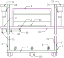
Fig. 1 is an overall front view of the cylinder type elevator of the present invention;
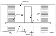
FIG. 2 is a schematic view of the connection between the first supporting plate and the lifting plate of the cylinder type elevator of the present invention;
fig. 3 is the utility model relates to a schematic diagram is connected with fly leaf to cylinder type lifting machine lifter plate.
In the figure: 1. a fixed base; 101. a roller; 2. a lifting mechanism; 21. a first mounting plate; 22. a second mounting plate; 23. a first cylinder; 24. a second cylinder; 25. a lifting plate; 3. a translation mechanism; 31. a third mounting plate; 32. a third cylinder; 33. a connecting plate; 34. a movable plate; 4. a first support plate; 41. a gear groove; 42. a chute; 5. a second support plate; 6. a spring; 7. a reinforcing plate; 8. a guard rail.
Detailed Description
The technical solutions in the embodiments of the present invention will be described clearly and completely with reference to the accompanying drawings in the embodiments of the present invention, and it is obvious that the described embodiments are only some embodiments of the present invention, not all embodiments. Based on the embodiments in the present invention, all other embodiments obtained by a person skilled in the art without creative work belong to the protection scope of the present invention.
Referring to fig. 1-3, the present invention provides a technical solution: a cylinder type elevator comprises a fixed base 1, an elevating mechanism 2 and a translation mechanism 3, wherein a plurality of rollers 101 are installed on the lower end face of the fixed base 1, a first supporting plate 4 and a second supporting plate 5 are respectively welded on two sides of the upper end face of the fixed base 1, gear grooves 41 are respectively welded on two ends of one side of the first supporting plate 4 and the second supporting plate 5, which is close to the middle of the fixed base 1, the elevating mechanism 2 is installed on the first supporting plate 4 and the second supporting plate 5, the elevating mechanism 2 is composed of a first installing plate 21, a second installing plate 22, a first cylinder 23, a second cylinder 24 and an elevating plate 25, the first installing plate 21 is welded on the upper end of one side of the first supporting plate 4, which is far away from the second supporting plate 4, the second installing plate 22 is welded on the upper end of one side of the second supporting plate 5, the first cylinder 23 and the second cylinder 24 are respectively installed on the lower end faces of the first installing plate 21, lifter plate 25 is installed through the bolt to the lower extreme of first cylinder 23, and bolted connection is passed through with the output of second cylinder 24 to the other end of lifter plate 25, all offer on first backup pad 4 and the second backup pad 5 with lifter plate 25 assorted spout 42, the both sides at lifter plate 25 both ends all are installed the gear and are connected with the meshing of gear groove 41, and translation mechanism 3 installs on elevating system 2.
The translation mechanism 3 is composed of a third mounting plate 31, a third cylinder 32, a connecting plate 33 and a movable plate 34, the third mounting plate 31 is welded at the lower end of one side of the lifting plate 25 close to the first cylinder 23, the third cylinder 32 is installed on the third mounting plate 31 through a bolt, the connecting plate 33 is installed at the output end of the third cylinder 32 through a bolt, the movable plate 34 is welded at the upper end of the connecting plate 33, and the movable plate 34 is in sliding connection with the upper end face of the lifting plate 25 in a groove mode.
The upper end face of the fixed base 1 is provided with a plurality of springs 6, which are beneficial to playing a certain buffer action on the lifting plate 25.
Reinforcing plates 7 are welded on two sides of the lower ends of the first supporting plate 4 and the second supporting plate 5, and the lower ends of the reinforcing plates 7 are welded on the fixing base 1, so that the stability of the first supporting plate 4 and the stability of the second supporting plate 5 are improved.
The guard rail 8 is inserted into the upper end face of the lifting plate 25 through a small hole, and the protection of the rising materials is facilitated.
The lower end surface of the movable plate 34 is provided with a plurality of small balls, which is beneficial to reducing the friction force between the lifting plate 25 and the movable plate 34.
The working principle is as follows: when the device is used, firstly, the goods that need promote are placed on the lifter plate 25, then start first cylinder 23 and second cylinder 24, first cylinder 23 and second cylinder 24 upward movement, drive lifter plate 25 upward movement from both sides, inject through gear groove 41, guarantee that lifter plate 25 fast and stable rises, simultaneously when the goods rises to appointed height, can start third cylinder 32 according to the needs of operation, third cylinder 32 promotes connecting plate 33 and moves, connecting plate 33 drives movable plate 34 and moves, thereby adjust the position of horizontal direction, this device provides ascending effort from both sides, can promote fast effectively, high stability, reduce the consumption of human cost, can adjust the position of horizontal direction according to the demand of operation, realize the accurate of unloading of material, accord with the operation demand more.
It is noted that, herein, relational terms such as first and second, and the like may be used solely to distinguish one entity or action from another entity or action without necessarily requiring or implying any actual such relationship or order between such entities or actions. Also, the terms "comprises," "comprising," or any other variation thereof, are intended to cover a non-exclusive inclusion, such that a process, method, article, or apparatus that comprises a list of elements does not include only those elements but may include other elements not expressly listed or inherent to such process, method, article, or apparatus.
Although embodiments of the present invention have been shown and described, it will be appreciated by those skilled in the art that changes, modifications, substitutions and alterations can be made in these embodiments without departing from the principles and spirit of the invention, the scope of which is defined in the appended claims and their equivalents.
Claims (6)
1. The utility model provides a cylinder type lifting machine, includes unable adjustment base (1), elevating system (2) and translation mechanism (3), its characterized in that: the lower end face of the fixed base (1) is provided with a plurality of rollers (101), the two sides of the upper end face of the fixed base (1) are respectively provided with a first supporting plate (4) and a second supporting plate (5), the two ends of the first supporting plate (4) and the second supporting plate (5) close to one side of the middle of the fixed base (1) are respectively provided with a gear groove (41), the lifting mechanism (2) is arranged on the first supporting plate (4) and the second supporting plate (5), the lifting mechanism (2) is composed of a first mounting plate (21), a second mounting plate (22), a first cylinder (23), a second cylinder (24) and a lifting plate (25), the upper end of one side of the first supporting plate (4) far away from the second supporting plate (5) is provided with the first mounting plate (21), the upper end of one side of the second supporting plate (5) far away from the first supporting plate (4) is provided with the second mounting plate (22), be provided with first cylinder (23) and second cylinder (24) on the lower terminal surface of first mounting panel (21) and second mounting panel (22) respectively, the lower extreme of first cylinder (23) is provided with lifter plate (25), the other end of lifter plate (25) is connected with the output of second cylinder (24), all be provided with on first backup pad (4) and second backup pad (5) with lifter plate (25) assorted spout (42), the both sides at lifter plate (25) both ends all are provided with the gear and are connected with gear groove (41) meshing, translation mechanism (3) set up on elevating system (2).
2. The cylinder type hoist as claimed in claim 1, wherein: translation mechanism (3) comprise third mounting panel (31), third cylinder (32), connecting plate (33) and fly leaf (34), the lower extreme that lifter plate (25) is close to first cylinder (23) one side is provided with third mounting panel (31), be provided with third cylinder (32) on third mounting panel (31), the output on third cylinder (32) is provided with connecting plate (33), the upper end of connecting plate (33) is provided with fly leaf (34), fly leaf (34) activity sets up on the up end of lifter plate (25).
3. The cylinder type hoist as claimed in claim 1, wherein: the upper end face of the fixed base (1) is provided with a plurality of springs (6).
4. The cylinder type hoist as claimed in claim 1, wherein: both sides of first backup pad (4) and second backup pad (5) lower extreme all are provided with reinforcing plate (7), the lower extreme setting of reinforcing plate (7) is on unable adjustment base (1).
5. The cylinder type hoist as claimed in claim 1, wherein: a protective guard (8) is movably arranged on the upper end surface of the lifting plate (25).
6. The cylinder type hoist as claimed in claim 2, characterized in that: a plurality of small balls are movably arranged on the lower end surface of the movable plate (34).
Priority Applications (1)
| Application Number | Priority Date | Filing Date | Title |
|---|---|---|---|
| CN201921234498.2U CN210683073U (en) | 2019-08-01 | 2019-08-01 | Cylinder type elevator |
Applications Claiming Priority (1)
| Application Number | Priority Date | Filing Date | Title |
|---|---|---|---|
| CN201921234498.2U CN210683073U (en) | 2019-08-01 | 2019-08-01 | Cylinder type elevator |
Publications (1)
| Publication Number | Publication Date |
|---|---|
| CN210683073U true CN210683073U (en) | 2020-06-05 |
Family
ID=70902828
Family Applications (1)
| Application Number | Title | Priority Date | Filing Date |
|---|---|---|---|
| CN201921234498.2U Expired - Fee Related CN210683073U (en) | 2019-08-01 | 2019-08-01 | Cylinder type elevator |
Country Status (1)
| Country | Link |
|---|---|
| CN (1) | CN210683073U (en) |
Cited By (1)
| Publication number | Priority date | Publication date | Assignee | Title |
|---|---|---|---|---|
| CN112607278A (en) * | 2020-11-30 | 2021-04-06 | 周翔 | Automatic cargo transferring and storing system |
-
2019
- 2019-08-01 CN CN201921234498.2U patent/CN210683073U/en not_active Expired - Fee Related
Cited By (1)
| Publication number | Priority date | Publication date | Assignee | Title |
|---|---|---|---|---|
| CN112607278A (en) * | 2020-11-30 | 2021-04-06 | 周翔 | Automatic cargo transferring and storing system |
Similar Documents
| Publication | Publication Date | Title |
|---|---|---|
| CN211812921U (en) | Fixed hydraulic guide rail lift goods lift | |
| CN210762532U (en) | Automatic change intelligent stereoscopic warehouse | |
| CN214493037U (en) | Transfer equipment for electric machining | |
| CN209291346U (en) | A kind of machining Cubic stock picking system | |
| CN207759710U (en) | Frameless pallet disc stack machine | |
| CN205802899U (en) | A kind of lifting structures of Omni-mobile formula AGV | |
| CN102092557B (en) | Convenient-to-operate common conveying device for vehicle doors and trunk lids | |
| CN105857362B (en) | A kind of logistics trolley | |
| CN219488541U (en) | Pushing device for plate assembly line | |
| CN217946410U (en) | Automatic storage device of tobacco commodity circulation | |
| CN211309945U (en) | Plate conveying machine for producing interlocking blocks | |
| CN110342270A (en) | A kind of automatic clamping and the robot device of stacking | |
| CN210441964U (en) | A roller body weighing device | |
| CN220578815U (en) | Construction lifting device for building security engineering | |
| CN203144028U (en) | Reciprocating elevator | |
| CN208161991U (en) | Three station elevating mechanism of separator | |
| KR200345003Y1 (en) | Dry-film laminator | |
| CN214570028U (en) | Be used for mud flat photovoltaic construction battery piece upper rack hoist device | |
| CN219216290U (en) | A logistics storage lifting device | |
| CN211769107U (en) | A paper separator loading and feeding device | |
| CN219075124U (en) | Plain plate sander for plate processing | |
| CN213505162U (en) | S-shaped tension regulation and control structure | |
| CN221274583U (en) | Acrylic plate separating conveyor | |
| CN212583170U (en) | Automatic change equipment fixing adjusting device | |
| CN216104114U (en) | Tray storage mechanism of sponge clout storage rack |
Legal Events
| Date | Code | Title | Description |
|---|---|---|---|
| GR01 | Patent grant | ||
| GR01 | Patent grant | ||
| CF01 | Termination of patent right due to non-payment of annual fee |
Granted publication date: 20200605 Termination date: 20210801 |
|
| CF01 | Termination of patent right due to non-payment of annual fee |