CN210676435U - High-precision steel coil uncoiling machine - Google Patents
High-precision steel coil uncoiling machine Download PDFInfo
- Publication number
- CN210676435U CN210676435U CN201921735029.9U CN201921735029U CN210676435U CN 210676435 U CN210676435 U CN 210676435U CN 201921735029 U CN201921735029 U CN 201921735029U CN 210676435 U CN210676435 U CN 210676435U
- Authority
- CN
- China
- Prior art keywords
- plate
- fixedly provided
- steel coil
- driving motor
- precision steel
- Prior art date
- Legal status (The legal status is an assumption and is not a legal conclusion. Google has not performed a legal analysis and makes no representation as to the accuracy of the status listed.)
- Expired - Fee Related
Links
- 229910000831 Steel Inorganic materials 0.000 title claims abstract description 18
- 239000010959 steel Substances 0.000 title claims abstract description 18
- 230000005540 biological transmission Effects 0.000 claims description 14
- 230000003139 buffering effect Effects 0.000 claims description 8
- 230000033001 locomotion Effects 0.000 abstract description 10
- 238000000034 method Methods 0.000 abstract description 4
- 230000000694 effects Effects 0.000 abstract description 3
- 239000000463 material Substances 0.000 abstract description 3
- 238000009434 installation Methods 0.000 description 3
- 238000001125 extrusion Methods 0.000 description 2
- 230000000052 comparative effect Effects 0.000 description 1
- 239000002184 metal Substances 0.000 description 1
- 238000011017 operating method Methods 0.000 description 1
- 238000010008 shearing Methods 0.000 description 1
Images


Landscapes
- Winding, Rewinding, Material Storage Devices (AREA)
Abstract
The utility model belongs to the field of decoiler, in particular to a high-precision steel coil decoiler, which aims at the problem that the prior decoiler can easily cause uneven stress on a roller shaft once individual mechanical failure occurs, so that the levelling effect is greatly reduced, and provides the following proposal, which comprises a case, wherein the top parts of both sides of the case are fixedly provided with a placing platform, the top part of the case is symmetrically and fixedly provided with two sliding covers, the top parts of the two sliding covers are fixedly provided with the same U-shaped plate, a driving motor is fixedly arranged on one side of the top of the U-shaped plate, the utility model respectively starts the rotating motor and the driving motor, the purpose of leveling the sheet material can be realized by the left-right reciprocating motion of the rollers on the sheet material, and the technical proposal adopts a single group of rollers to work, therefore, the problem of fold marks of the plate in the leveling process can be effectively avoided without adjustment.
Description
Technical Field
The utility model relates to an open flat-bed machine technical field, especially relate to a flat-bed machine is opened to high accuracy steel book.
Background
The decoiler is a machine for decoiling, leveling and shearing a series of processing operations of metal plates. The decoiler is generally used in the steel market, and very wide materials are flattened and sheared by the decoiler to become coil stock or plate stock with comparative specifications.
The existing uncoiling machine generally adopts a plurality of groups of roll shafts to pressurize and flatten the plates, but the plate can be flattened only by ensuring the consistent pressure of the roll shafts in such a mode, and the roll shafts are unevenly stressed easily in case of individual mechanical faults, so that the flattening effect is greatly reduced, and the high-precision steel coil uncoiling machine is provided for solving the problems.
SUMMERY OF THE UTILITY MODEL
The utility model aims at solving and having the flatting mill of opening to adopt the multiunit roller generally among the prior art, carry out the flattening of pressurizeing to panel, nevertheless such mode need guarantee that the pressure of multiunit roller is unanimous could the flattening panel, in case individual mechanical failure appears will cause the roller atress uneven easily for flattening effect greatly reduced's shortcoming, and the flatting mill is opened to a high accuracy steel book that provides.
In order to achieve the above purpose, the utility model adopts the following technical scheme:
the utility model provides a flat-bed machine is driven to high accuracy steel book, includes quick-witted case, the equal fixed mounting in both sides top of quick-witted case has the platform of placing, and the top symmetry fixed mounting of quick-witted case has two slip covers, and the top fixed mounting of two slip covers has same U template, top one side fixed mounting of U template has driving motor, and sliding connection has same movable plate on two slip covers, driving motor's output shaft and movable plate transmission are connected, the top fixed mounting of movable plate has the rotation motor, and has seted up the removal hole on the movable plate, sliding connection has the erection column on the inner wall in removal hole, the bottom of erection column extends to the below and the fixed mounting of movable plate has the mounting bracket, swing joint has the gyro wheel on the.
Preferably, driving motor's output shaft extends to in the U template, and rotates on the top one side inner wall of U template and be connected with the pivot, equal fixed mounting has the carousel on the bottom of pivot and driving motor's the output shaft, and transmission connection has same drive belt on two carousels, the drive belt is connected with the movable plate transmission, utilizes the drive belt, can conveniently drive the movable plate and carry out horizontal reciprocating motion.
Preferably, a connecting cover is fixedly mounted on one side of the top of the moving plate, a connecting shaft is movably connected in the connecting cover, the top end of the connecting shaft extends to the upper side of the connecting cover and is fixedly connected with a driving belt, and the driving belt and the moving plate can be in transmission connection by means of the connecting shaft and the connecting cover.
Preferably, fixed mounting has the screw rod on the output shaft of rotation motor, and the top of erection column has seted up the spread groove, the bottom of screw rod extend to in the spread groove and with the inner wall threaded connection of spread groove, utilize to rotate the motor and can conveniently drive the erection column and carry out longitudinal movement.
Preferably, the equal fixed mounting in both sides of mounting bracket has spacing cover, sliding connection has the connecting plate on one side inner wall of spacing cover, and rotates on two connecting plates and be connected with same installation axle, the gyro wheel fixed cover is established at the installation epaxially, the top fixed mounting of spacing cover has the buffering hydraulic stem, the one end of buffering hydraulic stem extend to in the spacing cover and with the top fixed connection of connecting plate, utilize the buffering hydraulic stem can realize the elastic support to the gyro wheel to this can realize the gyro wheel with panel in close contact with the condition under, also can prevent to panel extrusion excessively.
The utility model discloses in, high accuracy steel coil decoiler
The uncoiled plate is placed at the top of the case, then the rotating motor can be started to drive the screw rod to rotate, so that the mounting column can be driven to move downwards, and when the mounting column moves downwards, the roller can be driven to move downwards until the roller is contacted with the plate;
the driving motor is started to drive one of the turntables to rotate, so that the driving belt can be driven to move, the connecting shaft can be driven to do annular motion, and at the moment, the movable plate can do transverse reciprocating motion along with the connecting shaft under the action of the connecting cover, so that the roller can be driven to roll left and right, and the plate can be leveled;
the utility model discloses a start respectively and rotate motor and driving motor, can be in order to realize that the gyro wheel carries out reciprocating motion about on panel, alright realize carrying out the purpose of flattening to panel to this technical scheme has adopted single group gyro wheel to carry out work, so need not adjust, so can effectively avoid the problem of fold impression to appear at the in-process of flattening in panel.
Drawings
FIG. 1 is a front view of a high-precision steel coil uncoiling machine according to the present invention;
FIG. 2 is a front view of the U-shaped plate and the sliding cover structure of the high-precision steel coil decoiling machine of the present invention;
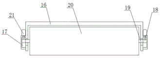
fig. 3 is the utility model provides a roller bearing and spacing cover connection structure elevation of high accuracy steel coil decoiler machine.
In the figure: the device comprises a case 1, a placing table 2, a sliding cover 3, a U-shaped plate 4, a driving motor 5, a rotating shaft 6, a driving belt 7, a connecting shaft 8, a connecting cover 9, a moving plate 10, a rotating motor 11, a moving hole 12, a mounting column 13, a connecting groove 14, a screw rod 15, a mounting frame 16, a limiting cover 17, a connecting plate 18, a mounting shaft 19, a roller 20 and a buffer hydraulic rod 21.
Detailed Description
The technical solutions in the embodiments of the present invention will be described clearly and completely with reference to the accompanying drawings in the embodiments of the present invention, and it is obvious that the described embodiments are only some embodiments of the present invention, not all embodiments.
Example one
Referring to fig. 1-3, a high-precision steel coil decoiler comprises a case 1, a placing table 2 is fixedly mounted at the tops of two sides of the case 1, two sliding covers 3 are symmetrically and fixedly mounted at the top of the case 1, the same U-shaped plate 4 is fixedly mounted at the tops of the two sliding covers 3, a driving motor 5 is fixedly mounted on one side of the top of the U-shaped plate 4, the same moving plate 10 is connected onto the two sliding covers 3 in a sliding mode, an output shaft of the driving motor 5 is in transmission connection with the moving plate 10, a rotating motor 11 is fixedly mounted at the top of the moving plate 10, a moving hole 12 is formed in the moving plate 10, a mounting column 13 is connected onto the inner wall of the moving hole 12 in a sliding mode, the bottom end of the mounting column 13 extends to the lower side of the moving plate.
Wherein, the uncoiled plate is placed on the top of the case 1, then the rotating motor 11 can be started to drive the screw 15 to rotate, so as to drive the mounting post 13 to move downwards, when the mounting post 13 moves downwards, the roller 20 can be driven to move downwards until the roller 20 contacts with the plate, the driving motor 5 is started to drive one of the turntables to rotate, namely, the driving belt 7 can be driven to move, so as to drive the connecting shaft 8 to move in a circular manner, at the moment, the movable plate 10 can move in a transverse reciprocating manner along with the connecting shaft 8 under the action of the connecting cover 9, so as to drive the roller 20 to roll left and right, so as to realize the leveling of the plate, the utility model can realize the left and right reciprocating movement of the roller 20 on the plate by respectively starting the rotating motor 11 and the driving motor 5, alright realize carrying out the purpose of flattening to panel to this technical scheme has adopted single group of gyro wheel 20 to work, so need not adjust, so can effectively avoid the problem that the fold impression appears in the in-process of panel at the flattening.
Example two
The utility model discloses in, driving motor 5's output shaft extends to in the U template 4, and rotates on one side of the top inner wall of U template 4 and be connected with pivot 6, and equal fixed mounting has the carousel on the bottom of pivot 6 and driving motor 5's the output shaft, and transmission connection has same drive belt 7 on two carousels, and drive belt 7 is connected with the transmission of movable plate 10, utilizes drive belt 7, can conveniently drive movable plate 10 and carry out horizontal reciprocating motion.
The utility model discloses in, top one side fixed mounting of movable plate 10 has connecting cover 9, and swing joint has connecting axle 8 in the connecting cover 9, and the top of connecting axle 8 extends to the top of connecting cover 9 and with 7 fixed connection of drive belt, utilizes connecting axle 8 and connecting cover 9 can realize that drive belt 7 carries out the transmission with movable plate 10 and is connected.
The utility model discloses in, fixed mounting has screw rod 15 on the output shaft of rotation motor 11, and the top of erection column 13 has seted up spread groove 14, and screw rod 15's bottom extend to in spread groove 14 and with spread groove 14's inner wall threaded connection, utilize rotation motor 11 can conveniently drive erection column 13 and carry out longitudinal movement.
The utility model discloses in, the equal fixed mounting in both sides of mounting bracket 16 has spacing cover 17, sliding connection has connecting plate 18 on one side inner wall of spacing cover 17, and rotate on two connecting plates 18 and be connected with same installation axle 19, gyro wheel 20 fixed cover is established on installing axle 19, the top fixed mounting of spacing cover 17 has buffering hydraulic stem 21, the one end of buffering hydraulic stem 21 extend to in spacing cover 17 and with the top fixed connection of connecting plate 18, utilize buffering hydraulic stem 21 can realize the elastic support to gyro wheel 20, with this can realize gyro wheel 20 under the condition with panel in close contact with, also can prevent excessively to the panel extrusion.
The utility model discloses in, driving motor 5 all adopts external 220V alternating current power supply with rotation motor 11 among this technical scheme, and specific operating procedure is: firstly, the uncoiled plate is placed at the top of the case 1, then the rotating motor 11 can be started to drive the screw rod 15 to rotate, so that the mounting column 13 can be driven to move downwards, when the mounting column 13 moves downwards, the roller 20 can be driven to move downwards until the roller 20 is contacted with the plate, then when the mounting column 13 moves downwards, pressure can be applied to the roller 20, at the moment, two buffer hydraulic rods 21 can be used for applying elasticity to the roller 20, so that the roller 20 can be in close contact with the plate, the driving motor 5 is started to drive one of the turntables to rotate, so that the driving belt 7 can be driven to move, so that the connecting shaft 8 can be driven to do annular motion, at the moment, under the action of the connecting cover 9, the moving plate 10 can be transversely reciprocated along with the connecting shaft 8, so that the roller 20 can be driven to roll left and right, so can realize carrying out the flattening to panel to this technical scheme has adopted single group of gyro wheel 20 to work, so need not adjust, so can effectively avoid the problem of panel fold impression to appear at the in-process of flattening.
The above, only be the concrete implementation of the preferred embodiment of the present invention, but the protection scope of the present invention is not limited thereto, and any person skilled in the art is in the technical scope of the present invention, according to the technical solution of the present invention and the utility model, the concept of which is equivalent to replace or change, should be covered within the protection scope of the present invention.
Claims (5)
1. The high-precision steel coil decoiler comprises a case (1) and is characterized in that the tops of two sides of the case (1) are fixedly provided with a placing table (2), the top of the case (1) is symmetrically and fixedly provided with two sliding covers (3), the tops of the two sliding covers (3) are fixedly provided with the same U-shaped plate (4), one side of the top of the U-shaped plate (4) is fixedly provided with a driving motor (5), the two sliding covers (3) are connected with the same moving plate (10) in a sliding manner, an output shaft of the driving motor (5) is in transmission connection with the moving plate (10), the top of the moving plate (10) is fixedly provided with a rotating motor (11), the moving plate (10) is provided with a moving hole (12), the inner wall of the moving hole (12) is connected with a mounting column (13) in a sliding manner, the bottom end of the mounting column (13) extends to the lower part of the moving plate (10, the mounting frame (16) is movably connected with a roller (20).
2. The high-precision steel coil decoiler according to claim 1, characterized in that the output shaft of the driving motor (5) extends into the U-shaped plate (4), the inner wall of one side of the top of the U-shaped plate (4) is rotatably connected with a rotating shaft (6), the bottom end of the rotating shaft (6) and the output shaft of the driving motor (5) are both fixedly provided with turntables, the two turntables are in transmission connection with the same transmission belt (7), and the transmission belt (7) is in transmission connection with the movable plate (10).
3. The high-precision steel coil uncoiling machine according to claim 1, wherein a connecting cover (9) is fixedly installed on one side of the top of the moving plate (10), a connecting shaft (8) is movably connected in the connecting cover (9), and the top end of the connecting shaft (8) extends to the upper side of the connecting cover (9) and is fixedly connected with the transmission belt (7).
4. The high-precision steel coil uncoiling machine according to claim 1, wherein a screw (15) is fixedly mounted on an output shaft of the rotating motor (11), a connecting groove (14) is formed at the top end of the mounting column (13), and the bottom end of the screw (15) extends into the connecting groove (14) and is in threaded connection with the inner wall of the connecting groove (14).
5. The high-precision steel coil decoiler according to claim 1, characterized in that limiting covers (17) are fixedly mounted on two sides of the mounting frame (16), a connecting plate (18) is slidably connected to an inner wall of one side of each limiting cover (17), a same mounting shaft (19) is rotatably connected to the two connecting plates (18), the rollers (20) are fixedly sleeved on the mounting shafts (19), a buffering hydraulic rod (21) is fixedly mounted at the top of each limiting cover (17), and one end of each buffering hydraulic rod (21) extends into each limiting cover (17) and is fixedly connected with the top of each connecting plate (18).
Priority Applications (1)
| Application Number | Priority Date | Filing Date | Title |
|---|---|---|---|
| CN201921735029.9U CN210676435U (en) | 2019-10-16 | 2019-10-16 | High-precision steel coil uncoiling machine |
Applications Claiming Priority (1)
| Application Number | Priority Date | Filing Date | Title |
|---|---|---|---|
| CN201921735029.9U CN210676435U (en) | 2019-10-16 | 2019-10-16 | High-precision steel coil uncoiling machine |
Publications (1)
| Publication Number | Publication Date |
|---|---|
| CN210676435U true CN210676435U (en) | 2020-06-05 |
Family
ID=70889847
Family Applications (1)
| Application Number | Title | Priority Date | Filing Date |
|---|---|---|---|
| CN201921735029.9U Expired - Fee Related CN210676435U (en) | 2019-10-16 | 2019-10-16 | High-precision steel coil uncoiling machine |
Country Status (1)
| Country | Link |
|---|---|
| CN (1) | CN210676435U (en) |
Cited By (1)
| Publication number | Priority date | Publication date | Assignee | Title |
|---|---|---|---|---|
| CN113682029A (en) * | 2021-08-30 | 2021-11-23 | 南京铭客传动系统有限公司 | Static equal-pressure type double-steel-belt continuous press |
-
2019
- 2019-10-16 CN CN201921735029.9U patent/CN210676435U/en not_active Expired - Fee Related
Cited By (2)
| Publication number | Priority date | Publication date | Assignee | Title |
|---|---|---|---|---|
| CN113682029A (en) * | 2021-08-30 | 2021-11-23 | 南京铭客传动系统有限公司 | Static equal-pressure type double-steel-belt continuous press |
| CN113682029B (en) * | 2021-08-30 | 2023-04-25 | 南京铭客传动系统有限公司 | Static-equal-pressure double-steel-belt continuous press |
Similar Documents
| Publication | Publication Date | Title |
|---|---|---|
| CN203695663U (en) | Straightening machine for steel tube | |
| CN208067227U (en) | Convertible forging apparatus | |
| CN203678924U (en) | H-shaped steel flange straightening machine | |
| CN205650632U (en) | Plate bending machine | |
| CN204381994U (en) | The bar-shaped zero firmware aligning sanding apparatus of automobile mechanical | |
| CN102310095A (en) | Front steel turning device of cogging mill | |
| CN113617906A (en) | High-speed D-shaft bending mechanism | |
| CN204321018U (en) | A kind of punch press auxiliary manipulator | |
| CN106429655B (en) | A kind of steel band draw off gear safe to use | |
| CN104492879A (en) | Rolling machine with rollers adjustable independently | |
| CN222177050U (en) | A kind of equipment for polishing weld seam on inner wall of shrinking cylinder | |
| CN220072844U (en) | A cold rolled steel plate unwinding machine | |
| CN217165814U (en) | Replacement device for steel pipe welding roller | |
| CN112719896B (en) | Street lamp processing cutting device | |
| CN209035170U (en) | Aluminium strip apparatus for correcting for production of aluminum | |
| CN202238943U (en) | Fully-hydraulic-driven steel turning device for use before blooming mill | |
| CN102274844B (en) | Arrangement structure for brush rolls of brushing device in metal plate production line | |
| CN108655941A (en) | Suitable for sign board surface polishing device | |
| CN201205567Y (en) | Simple leveling machine for coiling band steel | |
| CN201020916Y (en) | Work-piece supporting device of gilding press | |
| CN222137093U (en) | Auxiliary table for cold rolled sheet production | |
| CN221734467U (en) | A leveling mechanism for an aluminum plate leveling machine | |
| CN220072811U (en) | Roller positioning and adjusting mechanism | |
| CN217069215U (en) | Shaking table for mineral separation with tilting mechanism | |
| CN223980996U (en) | A roller balancing device for a tension leveling machine |
Legal Events
| Date | Code | Title | Description |
|---|---|---|---|
| GR01 | Patent grant | ||
| GR01 | Patent grant | ||
| CF01 | Termination of patent right due to non-payment of annual fee | ||
| CF01 | Termination of patent right due to non-payment of annual fee |
Granted publication date: 20200605 Termination date: 20201016 |